After restyling in 2003 and 2010, the popular truck in Russia received a new name - “Gazelle-Business”. But not only did the car receive a prefix to its name and a modified cladding - more than 20 components were modified, and in total the automaker made 130 changes to the design, including a redesigned electrical circuit.
If we compare the first-born, which was released back in 1994, and the new product, the alterations turned out to be significant. The maintenance experience accumulated over the years of operation allowed us to formulate tasks for designers and engineers, which were implemented in the new model.
Restyled Gazelle Business
Radical changes to the electrical circuit
In particular, the electrical wiring of the Gazelle 3302 has changed significantly due to the appearance of long-awaited elements:
- Diesel engine;
- ABS in the brake drive;
- Air conditioning;
- Cruise control.
Diesel Gazelle
Factory wiring diagram Gazelle 3302
With the advent of long-awaited diesel engines in the line of power units, in particular, a Cummins engine made in the USA, the electrical equipment layout has also changed.
Although the diesel engine is free of the ignition system traditional for gasoline engines, its design contains a lot of other electrical components, among which the main ones are:
- Fuel pump control unit;
- Exhaust gas afterburning system control unit.
Caution: using non-standard firmware for the engine control unit is not recommended, since the factory settings are designed to balance the different torque of the engine and gearbox.
Accordingly, the wiring of the Gazelle Business has also undergone changes (compared to the wiring diagram of the Gazelle with the 402 engine), since in the diesel version the following is installed:
- more powerful battery,
- new starter with improved characteristics;
- high performance generator;
The installation of energy-intensive equipment led to an increase in the load on the on-board network, which also required alteration of the Gazelle's electrical wiring diagram. Naturally, the automaker began shipping electrical wiring kits corresponding to different power units to service points and auto parts stores.
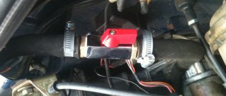
Sanden air conditioners
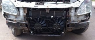
With the advent of air conditioners from the Japanese company Sanden, the electrical wiring on the Gazelle 3302 also underwent changes. In addition to additional consumers of the current source in the car interior (control unit), power was required in the engine compartment for both the electric fan and the pump.
Japanese Sanden air conditioner for Gazelle
Brake system
ABS, a system that prevents wheel locking during braking, also appeared on Gazelle Business for the first time.
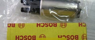
The automaker began installing products from the German company Bosch in the brake drive:
- master brake cylinder;
- vacuum brake booster;
- ABS control unit;
- wheel sensors.
For reference: Preference was given to a 4-channel system with separate adjustment of the braking torque of each wheel.
Since 2011, ABS has become the basic equipment of minibuses intended for transporting passengers.
Electrical circuit of the fuel pump in the injection VAZ 2110
The VAZ 2110 car with an injector system, even several years after the model was discontinued, is still very popular among car enthusiasts. The main reasons for this are the ease of maintenance and reliability of the machine. However, there are also negative aspects: the VAZ 2110 with an injector system very often has problems with electronics. The electrical circuit is quite complex for a Russian car and has 75 elements.
However, the weakest point is the fuel pump.
Its electrical circuit looks like this:
- The main one is the fuel pump relay; all the necessary fuses are installed there.
- Next, the electrical circuit diverges from one of the fuses to the diagnostic block and the device itself.
- From the next to the main relay and injectors.
- Next, the electrical circuit goes to the electronic control unit.
- Also, the fuel pump electrical circuit goes to the battery.
Thus, it turns out that the VAZ 2110 with an injector, the pump contains 4 electrical parts. In case of failures related to the operation of the pump, they should be checked first.
Principle of operation
To make it easier for you to understand the electrical circuit of the 2110 with the injector system, let’s consider its structure and the principle of operation itself.
So, the following take part in the process:
- Electronic control unit.
- Relay for turning on the fuel unit.
- Fuses that protect the electrical circuit of the device from overloads.
Wiring diagram VAZ 2110
In practice, the fuel unit starts working when the key is turned and ignites one turn. Before starting the engine, listen - at this moment you can hear the device starting to work and pumping gasoline.
Additional components
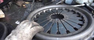
The Gazelle business wiring diagram has also undergone modification due to the appearance of:
- components and parts from ZF and Sachs in the clutch drive;
- power steering from ZF Lenksysteme;
- electrically heated exterior mirrors;
- a different front panel with a new instrument cluster;
- audio systems from Blaupunkt;
- updated cabin heater control unit.
Control unit for Blaupunkt audio system and air conditioning in Gazelle Business
In addition, cruise control of the Gazelle-Business family appeared as an option for the version with a power unit from Cummins, which also required changes to the electrical circuit of the car.
Conclusions: having subjected the Gazelle Business cars to modernization, the automaker has seriously improved the electrical wiring, for example, compared to the model with the 406 engine. That is why when replacing it or replacing its components, you should be guided by the manufacturer's electrical diagram.
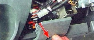
Wiring for Gazelle 405: problem with ground
Many owners of Gazelles with a 405 engine complain about sudden car failures , expressed in the problematic operation of the power unit. Symptoms are different for everyone - from “sneezing” and a complete stop, to the lack of engine response to the gas pedal. As experience shows, the culprit is poor-quality wiring on the Gazelle 405, or rather its individual elements.
Gazelle with an engine that meets EURO-3 standards
- General scheme
- Electronics help
- Vehicle weight
- We fix it ourselves
- Summary
Diaphragm fuel pump
Powered by camshaft eccentrics. Consists of separate prefabricated housing mechanisms with actuating lever and diaphragm. The pump valve contains a zinc holder, a rubber valve, and a brass plate, expanded by a bronze alloy spring. To filter the fuel, a brass mesh filter is installed above the pump valves.
If the engine is not running, you can fill the carburetor with fuel using the hand lever. To prevent the ingress of gasoline, the device is equipped with a mesh filter. If fuel stops being pumped, the fuel pump is replaced. "Gazelle" Business 4216 type with a carburetor allows for easy replacement, since the device is located outside the fuel tank.
Relocating the fuel tank
The need to move the UAZ tanks to the trunk was caused by the following: - Lack of protection: they hang under the belly, and if it’s problematic to break through, then denting is quite possible (my right one is dented) - To protect the tanks from corrosion - Moving the tank makes it possible to trim the sills and doors, in the future will allow you to install side protection for the jack - The tank in the trunk provides better weight distribution of the car. — It is necessary to increase the capacity (critical for long trips) — Increase the tightness. Perhaps this is only a problem for me, but after swimming in the ford, both tanks were filled with water, although the lids were tightly tightened (apparently leaky lids). I considered several options for replacement. It seemed to me difficult to move the standard ones and install 2 from the point of view of constructing a neck for filling (if placed on the floor of the trunk). The option of a welded stainless steel structure was rejected due to price (from 200-250 USD for the tank only). I didn’t like the often installed tank from ZIL because it has too much volume/space, I don’t need that much. And his neck is backwards. But on sale there are tanks from Gazelle, with different options for the outlet of the filler neck. I bought a tank with a side neck for 2000 rubles. (March 2005). It was not possible to find out the exact marking of the tank and the volume, but it seems to be from an onboard gazelle and the volume is 75 liters. A lot of extra parts were also purchased (see photo), the installation process revealed the most successful ones.
The tank is attached to the body floor with two metal strips using 4 M12 bolts and large washers. A camping mat is laid between the tank and the floor. An external frame is made from a 25x25 mm corner piece, which is lined with a steel sheet 0.8 mm thick (a sheet of 1.5x3 meters cost 500 rubles, almost all of it was used). The tank is shifted closer to the starboard side, on the left there is a small locker for either 2 batteries or spare parts. The neck is secured to the frame using a corner. There is a hole cut in the side for a hatch. I cut it with a grinder “with a reserve”, the edges were bent inward at 90 degrees. The hatch was secured using a piece of rectangular pipe. Unfortunately, the outlet tubes are installed in the tank only in a certain position, backwards. One of the pipes must be plugged (carb return). A fuel hose comes out from the other, a hole is cut directly in front of the rear side, a thick rubber hose is inserted into it, and a fuel hose is already passed into it. The hose is attached to the bottom of the body with a tie and stretched to the fuel pump, 4 meters is enough.
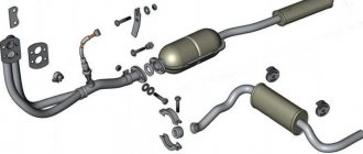
Fuel system diagram gazelle 405 injector
The fuel supply system for the UMZ-4216 engine on Gazelle and Sobol cars consists of a fuel tank, fuel lines, an electric fuel pump module with a fuel level sensor, a fine fuel filter, a fuel rail, and electromagnetic injectors.
Fuel supply system for the UMZ-4216 engine for Gazelle and Sobol, design, repair and maintenance of the fuel supply system.
The fuel supply system of the UMZ-4216 engine ensures the supply of the required amount of fuel to the engine cylinders in all operating modes. Fuel is supplied to the engine by four electromagnetic injectors. The fuel lines are made of steel tubes, which are connected to the engine, filter and submersible electric fuel pump module through fittings, conical couplings, union nuts and flexible hoses with clamps and quick-release connectors.
Fuel tank and tank cap of the fuel supply system of the UMZ-4216 engine for Gazelle and Sobol.
The fuel tank is located on the left side on the frame side member and is secured using brackets and clamps. Cardboard spacers are installed between the clamps and the tank. The fuel tank cap is equipped with a safety valve and a vacuum valve. The safety valve is activated when the excess pressure in the fuel tank is 10-18 kPa (1000-1800 mm water column), the vacuum valve - when the vacuum in the fuel tank is 3 kPa (300 mm water column), no more. The fuel tank capacity is 64+2 liters. Forcing additional fuel into the fuel tank is not permitted.
Fine fuel filter for the fuel supply system of the UMZ-4216 engine for Gazelle and Sobol.
The fine fuel filter is not dismountable and is replaced every 80,000 kilometers.
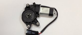
Submersible electric fuel pump module 155.1139002, 515.1139000-10, 9P2.960.031, 7D5.883.029 or EO4.4100000-21 for the fuel supply system of the UMZ-4216 engine for Gazelle and Sobol.
The submersible electric fuel pump module is designed to supply fuel under pressure to the injectors and provide control of the fuel level in the fuel tank. The module is installed in the fuel tank and is secured to the tank with a clamping ring through a rubber sealing ring with eight screws. The submersible electric fuel pump module consists of a cover, an electric fuel pump, an anti-drip cup, a strainer, a float, a fuel level sensor, a pressure reducing valve and a pressure ring.
On the module cover there are two fittings for connecting the fuel supply line and the fuel drain line, as well as an electrical connector for connecting the fuel level indicator sensor and the electric fuel pump to the vehicle's on-board network. The technical characteristics of the submersible electric fuel pump module are given in a separate material.
A strainer is installed at the inlet of the electric fuel pump to prevent mechanical impurities contained in the fuel from entering the pump. The anti-drip cup is designed to ensure a stable supply when there is a small amount of fuel in the tank.
Fuel rail of the fuel supply system for the UMZ-4216 engine on Gazelle and Sobol.
The fuel rail is designed to supply fuel under pressure to the injectors. The fuel rail is made of aluminum alloy in the form of a hollow rod with four sockets for articulation with injectors. The fuel supply is carried out through a threaded fitting installed at the rear end of the fuel rail.
During engine startup and operation, a constant fuel pressure difference between the injectors and the internal cavity of the intake pipe is maintained in the cavity of the fuel rail, which is equal to 4 kgf/cm2 (0.4 MPa). To attach the fuel rail to the cylinder head, there are two racks with mounting pads and mounting holes.
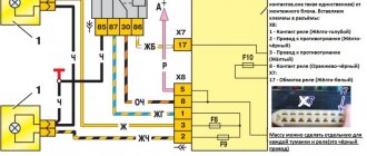
Gazelle fuel pump connector pinout
Electrical diagram of a Gazelle car
Electrical diagram of Gazelle cars with UMZ-4216, ZMZ-40522 engines : 1- left side turn signal; 2 – left headlight; 3 – right headlight; 4 – right side turn signal; 5 – starter; 6 – fuse box (in the engine compartment); 7 – headlight relay; 8 – central lighting switch; 9, 10 – lampshades for cargo compartment lighting (for vans); 11 – canopy lighting for the front part of the cabin; 12 – windshield washer motor; 13 – courtesy lamp for the rear part of the cabin (for vehicles with two rows of seats); 14 – switch for the interior lighting of the rear part of the cabin (for vehicles with two rows of seats); 15 – platform lamp (GAZ-3302, -33021, -33027); 16 – buzzer switch (GAZ-3302, -33021, -33027); 17 – driver signal buzzer (GAZ-3302, -33021, -33027); 18 – sound signals; 19 – sound signal relay; 20 – ignition switch; 21 – starter relay; 22 – generator; 23 – battery; 24 – battery switch; 25 – button for remote battery switch; 26 – electric drive of the heater valve; 27 – electric pump for additional heater; 28 – heater electric fan resistor; 29 – heater fan electric motor; 30 – heating and ventilation control panel (1 – heater tap switch; 2 – heating and ventilation control panel backlight lamp; 3 – relay; 4 – main heater electric fan switch; 5 – auxiliary heater electric fan and electric pump switch); 31 – upper fuse box (in the cabin); 32 – lower fuse block (in the cabin); 33 – engine compartment lamp; 34 – hazard warning light switch; 35 – radio receiver; 36 – resistor of the additional heater electric motor; 37 – additional heater electric motor; 38 – interior lamp switch (right side); 39 – interior lamp switch (left side); 40 – lamp for lighting the steps (for buses); 41 – interior lamps (right side); 42 – interior lamp (left side); 43 – cigarette lighter; 44 – switch for checking the serviceability of signaling devices; 45 – sensor for emergency drop in brake fluid level; 46 – right steering column switch (switch for direction indicators and headlights); 47 – direction indicator relay; 48 – switch for electric headlight correctors; 49 – parking brake warning switch; 50 – parking brake warning relay; 51 – lighting control of the instrument cluster; 52 – connector (wire block) for connecting the ABS system; 53 – instrument cluster; 54 – brake signal switch; 55 – switch for the glove compartment lamp; 56 – lampshade lighting of the glove box; 57 – fuel module; 58 – center differential lock warning switch (for 4×4 vehicles); 59 – windshield wiper control relay; 60 – engine control system blocks; 61 – coolant temperature indicator sensor; 62 – coolant overheat indicator sensor; 63 – windshield wiper; 64 – oil pressure indicator sensor; 65 – emergency oil pressure indicator sensor; 66 – right steering column switch (horn and windshield wiper switch); 67 – speed sensor; 68 – reverse light switch; 69 – rear light (right); 70 – license plate lights; 71 – rear light (left)