Ignition module VAZ 2115 - check, malfunctions and replacement
To begin with, I would like to note that the ignition module on the VAZ 2115 is a fundamentally new device that is more reliable than what was installed on earlier models of VAZ cars.
The essence of the operation of this device is that it produces a high voltage electric current, which is subsequently transmitted to the spark plugs of the vehicle’s ignition system. Operating principle of the ignition module
As mentioned earlier, the main task of the ignition module is that it generates a high level of voltage, which is subsequently transmitted to the spark plugs. The generated current undergoes a compression procedure, as a result of which a working spark is supplied to one of the spark plugs of the ignition system, and an “idle” spark is supplied to the second. To be more correct in statements, the working spark is supplied to the first and fourth spark plugs of the vehicle’s ignition system, and the “idle” spark is supplied to the second and third. Thanks to this high-voltage electric current supply system, the spark appears at the right stroke and on the right cylinder, which ensures stable operation of the system.
Video. Checking the ignition module of the VAZ 2115
Power to the VAZ 2115 ignition module is supplied directly from the vehicle’s on-board electrical network. The voltage supplied to the ignition module is twelve volts. At the same time, you should know that the negative wire of the ignition module is attached directly to the vehicle body. Design of the VAZ 2115 ignition module
The vehicle ignition module consists of a housing made of plastic, a pair of electronic control units, a pair of high-voltage current transformers, and four outputs for BB-type wires. Dimensions of the VAZ 2115 ignition module: one hundred ten by one hundred seventeen by seventy. The weight of the ignition module is one kilogram, three hundred and twenty grams.
Operating principle of the ignition module
The supply of electric current is carried out using wires of the BB type; the supply of electric current is controlled using a special controller, which makes decisions based on information that comes to it from various sensors of the vehicle. Also, the controller’s tasks include setting the sequence in which the ignition coil operates.
The ignition module can carry out its uninterrupted operation at temperatures from minus forty degrees to plus one hundred and thirty degrees Celsius.
What are the signs that indicate a faulty ignition module?
There are several typical signs that directly indicate problems with the ignition module:
1. Engine idle floats.2. Engine traction periodically disappears for no reason.3. The car picks up engine speed very slowly when accelerating.4. The cylinders stop working in pairs.
Note that the same signs indicate a malfunction of the BB wires and spark plugs of the vehicle’s ignition system, so in the beginning, you should check them, and if everything is fine with them, then replace the ignition module.
Tools you will need:
To replace the ignition module on a VAZ 2115 car, you will need very few tools:
1. Open-end wrenches for seventeen and thirteen.2. Ten socket wrench.3. Hexagon.
Replacing the ignition module on a VAZ 2115 with your own hands
To independently replace the ignition module on a VAZ 2115, you should strictly adhere to a certain sequence of actions, which you can find below:
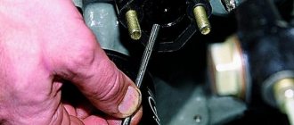
1. First, you must find the ignition module itself in the engine compartment. This can be done by following the high-voltage wires that come from the spark plugs of the ignition system.
2. Next, you must disconnect the negative cable from the battery.
3. Now, you need to remove the block to which the wires are connected from the ignition module.
4. Next, you should disconnect the high-voltage wires.
5. Now, you can unscrew the mounting bolts that secure the ignition module to the engine and remove it.
6. Then all you have to do is mount the new ignition module and assemble the entire structure in reverse order.
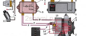
MODULE DEVICE
How to check the ignition module of a VAZ 2107 injector
The device includes two coils, the main task of which is to generate high voltage. A two-channel electronic switch helps them in this. All these parts are contained in a housing made of durable plastic. The housing has a low-voltage connector for connecting the supply voltage and supplying control pulses. There are also leads for connecting high-voltage wires that are connected to the spark plugs.
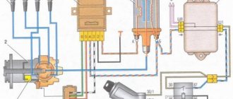
Electrical diagram of the VAZ 2114 starting system
The figure shows an electrical diagram of the VAZ 2114 starting system. As can be seen from the figure, it consists of:
- Battery;
- Ignition switch;
- Relay that turns on the ignition;
- Hall Sensor;
- Semiconductor signal receiver from the sensor;
- Electronic switch;
- Ignition module.
- High voltage terminals.
The electrical diagram also shows the fuses of the power supply circuits of the electronic units. Let's try to look at the device and operating principle of the ignition coil. As already noted, there are two of them in the block; they are identical in design. The ignition coil circuits of one and the other are also absolutely identical. The principle of operation of the ignition coil remains the same. Both consist of cores made of electrical steel. Two windings are wound on them. One of them is low-voltage, and the second produces high-voltage voltage to ignite the working mixture.
The ignition coil connection circuit is made in such a way that one end of the low-voltage winding is connected to the supply voltage, and the other end of these windings is connected to a transistor generator. Each coil has its own transistor. The high-voltage leads are connected directly to the spark plugs; each winding supplies energy to two spark plugs. One of them outputs pulses to cylinders 1 and 4, and the second to cylinders 2 and 3.
The wires on the ignition module are arranged as follows. Contacts A and B receive control pulses from the electronic switch, pin D receives power from the machine’s on-board network. The terminal marked with the letter C is connected to the vehicle ground.
ABOUT THE POSSIBILITIES OF MODULE REPAIR
Most breakdowns of this device lead to its replacement, but sometimes it is possible to repair the ignition coil to return it to service. This is especially true in cases where moving or tapping changes the behavior of the motor. If you have the ability to use a soldering iron and a multimeter, you can try to get it back into operation.
You need to remove the metal back cover, under which the electrical parts of the module are filled. You need to try to carefully get rid of the silicone and its “insides” will be revealed to your eyes. Find broken or “bad” contacts and solder them.
If the result is negative, then the block must be replaced. True, owners with extensive amateur radio experience continue to “dig” further. You can try replacing the electronic switches. Basically, these two elements become the culprits of failures of the engine starting system.
Ignition module (Ignition coil)
How to check the ignition module on a VAZ-2110 injector 16 valves: sharing knowledge
The ignition module is a complex electrical device designed to generate high voltage current (up to 30,000 V) and transmit it to the spark plugs. The connecting component between the ignition module and the spark plugs are high-voltage wires. It is worth noting that many car owners also call the ignition module the ignition coil, which is not entirely correct because
the coil is part of the ignition module, but in this case it is not important
Operating principle of the ignition module
The operating principle of the module corresponds to the operating principle of any ignition coil:
- The ECU controls the operation of the module by supplying direct current to its coil windings.
- According to the law of induction, high voltage is generated and supplied to the spark plug at the right moment.
- The ignition module consists of two ignition coils and two switches, as well as a plastic case and outputs to high-voltage wires. Each coil is connected to 2 cylinders: 1 coil – 1 and 4 cylinders, 2 coil – 2 and 3 cylinders.
Signs of a malfunctioning ignition module (coil)
The main signs of a malfunctioning ignition coil are:
- failures during acceleration;
- loss of power;
- unstable idle;
- 2-3 or 1-4 cylinders do not work.
If you encounter these symptoms of a malfunction, then in addition to the ignition module, it is recommended to check the following sensors: Mass air flow sensor. RXX. DMRV. DS.
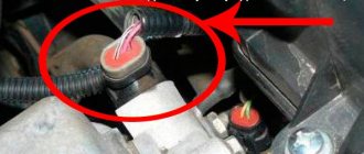
Where is the ignition module located?
The ignition module is located in the engine compartment. The easiest way to find it is to find high voltage wires. One end of the high-voltage wires goes to the spark plugs, the other end of the wires goes to the ignition module.
Connection diagram of explosive wires to the ignition module
High-voltage wires must be connected to the module strictly in a certain order:
Wires 1 and 4 of cylinders go to one winding, 2 and 3 to the other. Cylinder numbering is indicated on the ignition module
Pay attention to the picture
If you hold the module strictly in front of you, you need to connect it as follows:
- 1 cylinder – lower left high-voltage terminal;
- 2 cylinder – left upper high-voltage terminal;
- 3 cylinder – right upper high-voltage terminal;
- Cylinder 4 – lower right high-voltage terminal.
But this pinout is typical when you hold the module in front of you. If you want to install high-voltage wires on a module already installed on the machine, then the pinout is slightly different, because the module is installed at an angle (diamond):
- 1 cylinder – central lower outlet;
- 2nd cylinder – left output;
- 3 cylinder – top outlet;
- 4 cylinder – right output. But for convenience and clarity, it is better to remove the module and only then install high-voltage wires on it.
How to check the ignition module (coil)?
To check the module, you need to measure the resistance between the terminals (1 and 4 cylinders; and between 2 and 3 cylinders). The resistance on the ohmmeter should be approximately 5.4 kOhm. For a more detailed description of verification steps, read the article: How to check the ignition module?
Ignition module errors
The following errors are associated with malfunctioning ignition module:
- P0351 – coil breakage of cylinders 1-4.
- P0352 – coil breakage of cylinders 2-3.
- P3000 (P3001 P3002 P3003 P3004) – multiple misfires.
A common cause of this error can be both spark plugs and high-voltage wires - they need to be replaced (How to replace high-voltage wires? How to replace spark plugs?).
Checking for errors
Checking the ignition device for malfunctions always concerns the location of the wires on the ignition module of the VAZ 2114. For simple diagnostics, we simply measure the resistance between the wires of the first and fourth cylinders and the second and third cylinders with a multimeter. If the indicator is 5.5 kOhm (switch the multimeter to ohmmeter mode!), then everything is in order. There are also other checks:
- The first thing to check is the wiring block; it is better to disconnect it and check it with a multimeter in voltmeter mode: we attach the multimeter probe to pin A, and throw the other one onto the ground of the sliders. We start and look at the voltmeter values: excellent. If the voltage fluctuates around 12 V. If there is no voltage, check the ignition coil fuse, it may blow, as well as the correct connection of all contacts. By the way, about that. Another way of checking can indicate that the circuit of contacts is closed incorrectly: by connecting a tester to both contacts - A and B - connect a multimeter to it; if it blinks, then the circuit is in perfect order.
- It’s worth checking all the high-voltage elements (with the same multimeter in ohmmeter mode); if they are installed incorrectly, the ignition coil will burn out.
- To understand whether the ignition module behaves correctly, move the wire block, you can knock on it. The contact should not disappear, if the engine responds to your movements, the contact is unclear. It can break at any moment.
Symptoms of an ignition coil malfunction are often displayed by the system during basic diagnostics in a service center (or in a garage environment via a connected laptop with a special program) in the form of errors:
- P0351 – break in the winding of wires of cylinders 1-4
- P0352 – break in the wire winding of cylinders 2-3
- P3000 (P3001 P3002 P3003 P3004) – the ignition does not work.
All these errors are motivation for a deeper diagnosis of the situation, on which the decision will depend: replace the module with a new one, or repair it. Also, these errors may indicate a possible malfunction of one of the spark plugs or an explosive contact.
CHANGING THE IGNITION SYSTEM MODULE
When repairing the ignition module does not produce positive results, all that remains is to look for and install a new device. Most mechanics recommend choosing a “GM” device as a very reliable product. Its cost varies in different regions, but is close to 2000 rubles. Replacing the ignition module can be done independently, there are no special features, and no special devices are needed. For work, prepare:
- Ignition unit for replacement;
- Key to "13";
- Rags.
The work can easily be done in a garage or on level ground. Work order:
- Open the engine compartment hood and disconnect the battery terminals. It is quite enough to remove the terminal only from the negative side.
- After this, we remove the high-voltage wires from their installation locations. You need to remember where which wire was located. If you doubt your abilities, then make marks. Wires cannot be swapped. A new spare part can be damaged.
- At the next stage, carefully disconnect the connector with wires from the module. Use the key set to “13”, which unscrews the three nuts securing the device to the motor.
- When the nuts are removed, the device is removed from the engine.
Now they use rags to wipe the installation area and around it. Carefully inspect the new device and begin installing it. It is carried out in the reverse order to removal
Once again I would like to remind you of the importance of installing high-voltage wires in their places. If difficulties still arise, then take another look at the block
It shows the numbers of high-voltage wires.
HOW TO CHECK THE SYSTEM FOR OPERATION
In any case, the check begins with the candles. To do this, they need to be removed from their nests. This is also easy to do. Remove the tips of the high-voltage wires from them and, using a wrench for turning out the spark plugs, remove them from their places.
Next comes their inspection, cleaning and testing. They should have a working brown color, with no soot or soot. If their presence is observed, then there may be wear on the pistons and rings. In any case, the spark plugs are cleaned, checked and, if necessary, the gap between the electrodes is adjusted. After this you can check their functionality
There are special probes for these purposes. “Craftsmen” manage to make such products themselves from a piezo lighter. If nothing like this is available, then check it on the engine. It’s good if there is a car nearby with a known good starting system. This will make it possible to make an accurate diagnosis for candles. If they are in good condition, the search continues further.
Checking for the presence of high voltage is dangerous due to a possible sensitive electric shock, so we will touch on other methods. Let's talk about how you can determine ignition coil malfunctions and check this system:
- The simplest method is to replace the unit with a working device. It is not always possible, since not all drivers carry this device with them in reserve;
- They also advise, which has been tested many times, to move the device or knock on it while the motor is running. If changes are noticeable, they indicate poor contact inside the device. Sometimes it's fixable;
- Check with a tester or multimeter in resistance measurement mode. The resistance of the paired terminals of the coils, 1 and 4, as well as 2 and 3, is measured. It should be identical for both windings and equal to approximately 5.4 kOhm.
Ignition module diagram 2115
The ignition module installed on the Lada Samara is extremely resistant to both low and high temperatures. Operating temperature range: -400/+1300C.
The only negative point in the operation of this electronic device is its complete inability to repair. However, even a novice car enthusiast can replace it on his own.
Experts consider the most common malfunctions of the Samara ignition module to be:
Unstable operation of the power plant when accelerating the vehicle.
Decrease in engine power.
“Intermittent” idle speed.
Malfunction of paired (1/4 – 2/3) engine cylinders.
How to check the ignition module of a VAZ 2115
The correct operation of the VAZ 2115 ignition module determines not only the normal start of the engine, but also the stability of its operation in all modes. To fully check the serviceability of this element of the ignition system, you will need simple laboratory equipment. How to check the ignition module of a VAZ 2115 - preliminary results can be achieved in “field” conditions.
How to check the ignition module of a VAZ 2115
This electrical device creates high (up to 30,000 V) voltage, which is then transmitted to the spark plugs. Some car owners call this device a coil, although this is not entirely correct, since two coils are included in the module.
The 1st coil is responsible for the operation of cylinders 1 and 4, the 2nd for the operation of cylinders 2 and 3. In addition, the module contains 2 switches. These elements are located inside one plastic case. It is not difficult to find this module under the hood of the car; high-voltage wires go to it.
Among the main signs of a malfunctioning ignition module are loss of power, dips during a sharp increase in speed, unstable idle speed, and inoperative cylinders (1 and 4 or 2 and 3). These problems can be caused by a malfunction of the ignition module if the DS, MAF and IAC sensors are working properly.
Checking the VAZ 2115 module
Before you start testing the device, you must make sure that the wire blocks connected to it are in good condition. For these purposes you will need a tester. You should disconnect the block, then touch the “A” contact with one of the probes of the device, and the second to ground. After this, turn on the ignition and look at the tester readings.
The voltage should be 12 V. If it is missing, it can be argued that the fuse is faulty. At the next stage of checking the block, you will need a test light, which should be connected between the “A” and “B” contacts. Ask your assistant to turn the starter, and the light should blink. Otherwise, the wire going to the “A” contact may have broken. The same should be done with the “B” contact.
The easiest way to check the functionality of the module is to replace it with a working one. However, there are also nuances here. Ignition modules were installed on the very first Samaras. On later modifications, an ignition coil was installed, but the switch was part of the ECU, and therefore there was no separate module. This must be taken into account if you are going to use a donor car.
Another option for checking the ignition module of a VAZ 2115 is to measure the resistance. To do this, you need to touch the tester probes to the module output where the high-voltage wires are connected. Between the contacts going to cylinders 1 and 4 or 2 and 3, the resistance value will be 5.4 kOhm.
If the resistance indicator is normal, but the malfunction remains the same, use the method of “shaking” the module: lightly knocking on the device with the engine running. With changes in its operation, one can judge that there is poor contact between the elements located inside the ignition module.
We told you how to check the ignition module of a VAZ 2115, but it’s better not to fool your head and drop by the nearest car service center!
This blog is already read by 4756 people. Read it too!
Possible reasons for failure of the ignition module
Before repairing the main part in the car’s ignition system, you need to understand the nature of the problem. To do this, the consumer must be aware of the signs of a malfunction, as well as the causes of the breakdown.
The main reasons for device failure
Causes of problems:
- The ignition system uses spark plugs that do not match the vehicle parameters. They may not have the gap specified by the manufacturer. Also, the spark plugs themselves may not be working or dirty; this can be determined by visual diagnostics. If there are traces of carbon deposits on the devices, they must be removed.
- Malfunctions in the operation of the MH can arise as a result of frequent spark checks. At the time of diagnosis, a high load is placed on the device. If it appears frequently, it will lead to equipment failure or incorrect operation.
- The ignition module in the VAZ 2114 operates with the high-voltage cables disconnected. This also leads to device failure. The products themselves may be damaged, which affects the functioning of the engine as a whole.
- The device operates under severe vibration conditions. Their impact may be due to poor quality fixation of the module in the seat. As a result of vibrations, the factory soldering inside the equipment structure is damaged. This leads to its incorrect operation.
- The contact inside the plug with the low-voltage cables is broken.
- Initial use of a defective device or module with poor build quality. This factory defect can only be eliminated by replacing the mechanism; repairing the equipment is pointless.
- Moisture getting inside the case. This problem is unlikely, but exposure of the device to liquid may cause it to short out and break.
Signs of coil malfunction
The main symptoms of a malfunction in the VAZ 2114 ignition module:
- Difficulties arise when trying to start the engine. Starting the car engine may be difficult due to the fact that there is no spark on a spark plug or several.
- When idling or parking with the internal combustion engine running, the speed of the power unit floats. Their change is not associated with pressing the gas pedal and other third-party factors. This happens randomly.
- There are dips in the power of the car's engine. This is especially felt when driving uphill or sharp acceleration. Problems can also occur when driving on a flat road.
- Several cylinders stopped working. Usually these devices operate in pairs, so elements 1-4 or 2-3 could fail. Non-working cylinders may be indicated by “triple movement” of the engine.
- A “Check Engine” warning light appeared on the dashboard.
If the ignition module malfunctions, problems will appear not only in engine operation, but also when starting it.
The “Simple Opinion” channel, using the Lada Priora car as an example, spoke in detail about the symptoms that appear in the operation of the ignition modules.
Causes of ignition problems
As mentioned earlier, in order to set the ignition in the electronic system you will have to go into the “brains”, there you can also check the functionality of the sensors, so they greatly influence the operation of the system, regardless of the type of ignition.
On the electronic type, the main causes of failures are:
- Incorrect information transmitted from sensors to the ECU. If the connection to the brain and diagnostics showed strange data coming from one or more control devices, it is necessary to use a “substitution”. The easiest way is to find a car with known good sensors, install them and double-check the results. Here you need to understand that you do not need a new one, but a working sensor, because factory defects are not excluded even on a new mechanism.
- The incoming voltage - correct from a technical point of view is 5V, but if due to a violation of the mechanical integrity of the wires or another problem with the car’s electronics, this voltage changes, the sensor readings will also change after it. If this happens, the ECU begins to adjust engine operation based on incorrect data, which leads to incorrect operation of the entire mechanism as a whole. To check this breakdown, you will need a known-good system of wires leading to the sensor or a donor car into which you can install your sensor and test the system for functionality.
- Broken ECU - if the previous two options did not give a visible result, and installing your sensor and wiring in a working machine does not change its performance, only this option remains. You can try to reflash the “brain” of the car, but due to its low cost, it is better to immediately buy a new ECU and install it on the car.
Before moving on to the radical measures proposed in the third option, it is worth additionally checking the correct location of the labels. In cars with contactless ignition, this is the ignition installation of the VAZ 2114, and for cars with an electronic system, debugging is important to check the synchronization of the injection system with the gas distribution mechanism.
Read more: Dent repair, car painting
Service Manual
To ensure that electrical work does not cause trouble, the car owner must at least understand the electrical circuit of the VAZ. If a malfunction occurs in the operation of a particular equipment, using a diagram you can find out what the problem is and where to look for the cause. In some cases, a problem in the operation of certain devices can be solved by reconnecting the plug (if we are talking about poor contact of the device with the electrical network).
In practice, our compatriots often encounter problems with the operation of relays - the contact legs of these components can burn out as a result of voltage surges in the electrical network. Even if the relay legs are intact, but the equipment does not work, the device must be dismantled and disassembled - perhaps the contacts are burnt inside. If necessary, they can always be cleaned with a wire brush or sandpaper.
To prevent the battery from discharging, the battery must be recharged from time to time, especially before the onset of cold weather and at the end of winter. During the cold season, batteries discharge the fastest; this happens due to frost, so with the onset of winter, car owners often face the problem of starting the engine in the morning. If you doubt the battery's performance, you can try testing it with a multimeter; to do this, connect the tester probes to the battery terminals. Ideally, with the engine running, the battery voltage should be between 13.5 and 14 volts. If the resulting value is less or more, this indicates that the battery is not operating correctly.
Direct check of secondary coils for breakdown
To diagnose secondary elements of the MH for breakdown, you will also need a tester:
- All connected conductors must be disconnected from the device connectors.
- Diagnostic equipment is set to ohmmeter mode, the range of values is up to tens of ohms.
- The contact probes of the tester must be connected in turn to the paired connectors of the module. For example, in the second and third, as well as in the first and fourth.
- If the diagnostics showed the same results, then all windings are operational. The resistance parameter should be about 5.4 kOhm. If the values obtained are higher, this indicates an internal break in the device. With lower parameters, we can conclude that there is a breakdown.
Igor Belov shared effective options for diagnosing MH in garage conditions.
Checking the Lada Samara ignition module
The correct functioning of the ignition module not only has a significant impact on the start of the vehicle’s power plant, but also ensures the stability of its operation in all modes. To carry out a complete diagnosis of this electronic device, you need quite complex equipment, available only in large specialized workshops. However, you can check the functionality of the ignition module yourself in an amateur garage. The only logistical support for this test will be a multimeter, or tester.
The first and simplest way to determine the functionality of the ignition module is to replace it with a known-good device.
The procedure for replacing the ignition module includes the following steps:
- Preparation of the necessary tools: wrench 17 (open-end), wrench 13 (open-end), wrench 10 (socket), hexagon.
De-energizing the vehicle by disconnecting the “-” terminal from the battery.
Removing the wire block.
Disconnecting high voltage wires.
Unscrewing the fastenings to the power unit.
Recess of the ignition module (unscrews from the holder using a hexagon).
Installing a replacement module involves connecting high-voltage wires (the module body contains hints). In addition, the wire terminals also have corresponding designations. We install the ignition module, performing the manipulations in the reverse order, followed by checking its functionality.
Another method involves measuring the resistance of individual module elements using a multimeter (tester). Using the tester probes, we close the “paired” terminals of the module, which provide connection to high voltage wires, and measure the resistance value.
The resistance value of a working device should be approximately 5.4 kOhm. The discrepancy between this parameter and the specified value indicates that the VAZ 2115 ignition module is inoperative.
There is another, so-called “folk” method, or the “shake-up” method. With the power plant running, lightly tap the module. Despite all the “technical non-scientific” nature of such manipulations, they are capable of producing results. True, only in the case when the contact of the elements inside the housing is broken.
The ignition system of first-generation VAZ injection cars is, of course, far from perfect, but it is also less demanding in terms of maintenance and the qualifications of the technician. That is why even a not very experienced driver can check the ignition coil on a VAZ-2114. But you will have to check it if it is incorrect or the engine simply refuses to start.
Video with checking the ignition module and indicating reference values:
Replacing the ignition coil of Lada 2115 (VAZ 2115)
The ignition system (IS) is an important component of any vehicle. For trouble-free operation of the machine, it is necessary to monitor the serviceability of all components and parts. The article is devoted to the ignition lock (IZ), how to replace it, how the VAZ 2115 ignition coil is checked, how the ignition is set.
THIS IS INTERESTING: Why does the VAZ 2112 heat up?
Ignition switch and features of its replacement
ZZ plays an important role in the vehicle's SZ, both for an 8-cl and 16-cl engine. It is activated when the starter is working, thanks to it the lighting, turn signals, and power windows work.
Replacement or repair of the VAZ 2115 ignition switch may be required if:
- lost or broken keys;
- the lock was damaged during an attempted theft;
- the 3Z cylinder is faulty;
- The contact group does not work.
To replace you will need: a set of keys, a hammer, screwdrivers, a thin chisel.
The replacement procedure consists of the following steps:
- The car's power is turned off by disconnecting the negative terminal from the battery.
- We remove the steering wheel.
- Next you need to remove the steering column switches.
- Then you need to loosen the bolts securing the clamp that holds the ZZ on the steering column. If the heads are cut off, the bolts should be carefully knocked out using a hammer and a thin chisel.
- Now you need to disconnect the wiring harness.
- Next, you need to completely unscrew the bolts from the 3Z housing and you can remove it.
- A new device is installed in place of the old one.
- Assembly is carried out in reverse order.
After assembly, you should start the engine and check the operation of the switch (the author of the video is the MY LADA channel).
How to check the ignition coil?
Before diagnosing the ignition coil (SC) on an 8-valve engine, you should check whether there is voltage on the coil. To do this, you need to disconnect the wire block and check it with a tester. The voltage should be 12V.
Typical unit malfunctions
Signs of a faulty short circuit in VAZ engines with 8 valves, UAZs and other cars are similar:
- power is lost, it seems that the engine does not pull;
- the appearance of failures in engine operation;
- unstable operation at idle;
- Cylinders 2-3 and 1-4 do not function in pairs, there is no spark.
If the listed symptoms appear, you first need to check the spark plugs and crankshaft position sensor. Fuel injection into the injectors is regulated based on sensor readings, so if there is excessive fuel consumption, they require checking. The short circuit should be checked last.
You can check the ignition module (IM) on an 8-valve engine in one of three ways:
- The easiest way is to replace the module being tested with a known-good device. True, you need to find a suitable module. Before checking, be sure to make sure that the high-voltage wires are in good condition.
- The second method is to move the module. If, when you move it and the wire block, changes in the operation of the motor are noticeable, then there is a problem with the contacts. In this case, you can do the repair yourself. If repair is not possible, the device should be replaced.
- The third method is to check using a multimeter set to ohmmeter mode. It is necessary to measure resistance at the paired terminals of coils 2-3 and 1-4. It should be the same and be about 5.4 kOhm.
Instructions for repairing and replacing the ignition coil
Replacing short circuits on valves 8 and 16 in an engine represents a sequence of steps:
- The module can be easily found by the high voltage wires coming from the SZ spark plugs.
- Before starting work, you must turn off the negative voltage on the battery.
- The next step is to disconnect the wire block from the short circuit and high-voltage wires.
- Next, you need to unscrew the bolts securing the MZ to the engine, and you can dismantle the device.
- Now you need to install a new or repaired device and perform the steps in reverse order.
When connecting, follow the connection diagram in the manual.
How to set the ignition yourself?
Precise ignition adjustment on the VAZ 2115 injector is performed using a special strobe light. If this is not possible, you can set the ignition on the VAZ by spark.
To do this, follow these steps:
- First of all, the engine is warmed up until it reaches operating temperature.
- The distributor does not need to be removed, but only relaxed.
- You need to remove the central wire from the distributor.
- The piston in the 1st cylinder must be at TDC (the marks are set differently on 8 and 16 valve engines).
- Now you need to hold the short-circuit wire with your left hand and turn on the ignition.
- Use your right hand to adjust the distributor counterclockwise, while keeping the high-voltage wires above the metal.
- Then similar actions are performed, turning the distributor clockwise until a spark appears.
- At this point, the alignment ends, and the distributor is fixed in its regular place.
With the ignition set correctly, the car will operate without interruption with optimal fuel consumption and maximum power.
"Diagnostics of the ignition module"
This video demonstrates how to check the ignition module of a VAZ 2115 (the author of the video is Diary of AutoElectrika).
The ignition module on the VAZ 2114 and on other VAZ models is designed to supply high voltage through the PVN (high voltage wires) to the spark plugs. Some car owners call the ignition module a coil, which is not entirely correct. Ignition coils were installed in carburetor vases. The VAZ 2110-15 uses the ignition module.
Main function of the ignition module
The main task of the module is to supply current to the spark plugs. During operation, a working spark is supplied to one spark plug, and an “idle” spark to the other. The working spark is supplied to the 1st and 4th cylinders, and the idle spark is supplied to the 2nd and 3rd. Due to this connection, the spark appears in a timely manner in the desired cylinder during the required stroke. It is connected to the on-board network.
Operating principle and location
The ignition module is controlled by a controller, which in turn receives information about the state of the vehicle from various sensors (IAC, mass flow sensor and others). The controller also sets the sequence of operation of the ignition coils or, in other words, regulates the supply of current to the spark plugs. The ignition module operates at temperatures from −40° to +130°.
Finding its location is not difficult; high-voltage wires (HV) go from the module to the spark plugs; along them you can find the module.
- Lost engine thrust - the car “does not pull”
- The revolutions are floating
- The engine “troits”, that is, one or two cylinders may not work
- Dips during acceleration
If you notice that the car does not pull, that is, does not pick up speed when accelerating, one of the reasons may be a module failure. First of all, it is worth checking the night vision devices going from the coil to the candles. Perhaps some wire has fallen off the tip or is loose.
Diagram of the correct connection of wires to the ignition module
If, after checking the wires, you are convinced that they are all tightly connected to the spark plugs, let’s check that the wires themselves are connected correctly. Of course, if no one has climbed into the engine before you, then there is no point in checking. If there was traction and it disappeared, the reason could be both in the coil and in the wires themselves - they could be pierced. But in any case, let's check that the connection is correct. The ignition module shows the numbering of the cylinders to which the wires fit.
- 1 cylinder - central lower outlet
- 2 cylinder - left output
- 3 cylinder - top outlet
- 4 cylinder - right output
THIS IS INTERESTING: High fuel consumption of Priora
The diagram is shown for a coil installed on a vehicle.
If after checking no problems are identified, you should consider replacing the coil or wires. It is advisable to change both.
The cost of PVN, depending on the manufacturer, ranges from 300 to 600 rubles per set. The most popular manufacturers:
- TESLA
- BRISK
- BAUTLER
- Egorshinsk
The cost of an ignition coil is from 1300 to 2500 rubles. Modules from the following companies can be found in stores:
- SOATE (St. Oskol)
- MZATE
- HOFER
- FENOX
- BOSCH
When choosing a module, you should pay attention not only to the manufacturer, but also to the coil itself; it comes in old and new designs. Therefore, it is better to dismantle yours and bring it to the store.
Ignition module error codes
When diagnosing a car, the following error codes will be useful to you:
- P0351 - coil breakage of cylinders 1-4
- P0352 - coil breakage of cylinders 2-3
- P3000 (P3001 P3002 P3003 P3004) - multiple misfires.
Replacing the ignition module yourself
So, first of all, we are looking for a module (for those who don’t know). The PVNs from the spark plugs go to it.
- Remove the negative terminal from the battery
- Disconnect the wire block from the module
- Disconnect the PVN
- Unscrew the module itself and remove it
- Now install the new module and reassemble in reverse order.
When installing, do not confuse the position of the PVN on the reel.
Helpful note! If you are installing a new coil and old wires, pay attention to them. If there are yellow stripes on the tips of the spark plugs and wires, then the wires need to be replaced.
After replacing the module, you need to check its operation. We start the engine and enjoy the work done.
In the article brought to your attention, we will pay attention to an electronic device called the ignition module of the VAZ 2115 car. Or, more precisely, its description, circuit diagram and performance check.
This module consists of two high-voltage transformers and two control units (electronic), enclosed in a durable plastic case with four outputs of high-voltage wires. Electronic control units are also commonly called ignition coils, and one of them - “working” - is connected to the spark plugs of the first and fourth cylinders of the power unit, the other - “idle” - with the spark plugs of the second and third.
The VAZ 2115 ignition module is controlled by a controller whose operating functions include processing data received from vehicle system sensors: coolant temperature, rotation speed and position of the crankshaft, air flow, presence of detonation, etc.
The circuit diagram and connection diagram of this electronic device is presented below.
The only negative point in the operation of this electronic device is its complete inability to repair. However, even a novice car enthusiast can replace it on his own.
- Unstable operation of the power plant when accelerating the vehicle.
- Decrease in engine power.
- “Intermittent” idle speed.
- Malfunction of paired (1/4 - 2/3) engine cylinders.
Checking the Lada Samara ignition module
The correct functioning of the ignition module not only has a significant impact on the start of the vehicle’s power plant, but also ensures the stability of its operation in all modes.
To carry out a complete diagnosis of this electronic device, you need quite complex equipment, available only in large specialized workshops. However, you can check the functionality of the ignition module yourself in an amateur garage.
The only logistical support for this test will be a multimeter, or tester.
Attention! When using a donor car for testing, do not forget that only the first Lada Samara models were equipped with the ignition module, as a separate device. Machines of later releases are equipped with separate type devices (the switch is included in the electronic control unit).
The procedure for replacing the ignition module includes the following steps:
Another method involves measuring the resistance of individual module elements using a multimeter (tester). Using the tester probes, we close the “paired” terminals of the module, which provide connection to high voltage wires, and measure the resistance value.
There is another, so-called “folk” method, or the “shake-up” method. With the power plant running, lightly tap the module. Despite all the “technical non-scientific” nature of such manipulations, they are capable of producing results. True, only in the case when the contact of the elements inside the housing is broken.
Source: https://avtozam.ru/vaz/zamena-katushki-zazhiganiya-lada-2115-vaz-2115.html
How to check the system for functionality
In any case, the check begins with the candles. To do this, they need to be removed from their nests. This is also easy to do. Remove the tips of the high-voltage wires from them and, using a wrench for turning out the spark plugs, remove them from their places.
Next comes their inspection, cleaning and testing. They should have a working brown color, with no soot or soot. If their presence is observed, then there may be wear on the pistons and rings. In any case, the candles are cleaned. check and, if necessary, set the gap between the electrodes. After this you can check their functionality
There are special probes for these purposes. “Craftsmen” manage to make such products themselves from a piezo lighter. If nothing like this is available, then check it on the engine. It’s good if there is a car nearby with a known good starting system. This will make it possible to make an accurate diagnosis for candles. If they are in good condition, the search continues further.
Many publications recommend checking for the presence of high voltage voltage at the terminals of the device. Doing this in a garage is problematic due to the lack of a special measuring device. A conventional tester is used here, since it cannot measure several tens of kilovolts of high voltage. If you have experience as a radio amateur, you can assemble a voltage divider.
Checking for the presence of high voltage is dangerous due to a possible sensitive electric shock, so we will touch on other methods. Let's talk about how you can determine ignition coil malfunctions and check this system:
- The simplest method is to replace the unit with a working device. It is not always possible, since not all drivers carry this device with them in reserve;
- They also advise, which has been tested many times, to move the device or knock on it while the motor is running. If changes are noticeable, they indicate poor contact inside the device. Sometimes it's fixable;
- Check with a tester or multimeter in resistance measurement mode. The resistance of the paired terminals of the coils, 1 and 4, as well as 2 and 3, is measured. It should be identical for both windings and equal to approximately 5.4 kOhm.
https://youtube.com/watch?v=pNyBny-_HoQ
How to check the ignition module on a VAZ 2114
An ignition module is needed in a car to produce high voltage current, which then ignites the spark plugs. On different VAZ vehicles, a separate or block ignition module can be installed. In separate type modules, there is a separate coil for each cylinder. In block modules, one coil is used for two or all cylinders at once. It should be noted that the block ignition module is much easier to remove, check and install back, compared to a separate one.
The VAZ 2114 is now available with a block ignition module; its coil design includes: a core, a winding, high voltage wires and low voltage terminals.
How does a malfunction of the ignition module manifest itself:
Note. Some drivers believe that high-voltage wires and the ignition module are completely different things, and if the wires become faulty, the module will not be affected. This is mistake. If the wires are damaged, the spark may not fire accurately, which can result in the ignition module burning out altogether.
The easiest way to check the ignition module is to install a similar, working ignition module instead of your own. If this is not possible, then you can get by with a multitester or a regular 12-volt light bulb (“control”).
Checking the serviceability of the ignition module using a multitester
Checking the health of the winding
Set the multitester to ohmmeter mode to measure the resistance between the terminals of the secondary winding. Install the probes on the leads to the first and fourth cylinders, then to the second and third (see video below). Usually the tester shows a result close to 5.4 kOhm (plus or minus 0.1 kOhm). The main thing is that the resistance between paired terminals is approximately the same. If the difference exceeds 100 Ohms, then this is evidence of failure of the secondary winding.
Solution to the problem: replacing the ignition module.
Checking the serviceability of high-voltage wires
You need to “ring” the wire block. Set the multitester to voltmeter mode, disconnect the wire block from the ignition module. Place one probe on contact A, the second on engine ground. Have someone start the engine (or turn the starter), and you note the display readings for yourself. Normally, the voltage should be around 12 Volts. Do the same manipulation with the other contact.
If there is no voltage at all, then you need to check the fuse: it may have blown. There are three fuses on the VAZ 2114 electronic control unit. The third one from the top, rated 7.5 A, is the fuse for the ignition module.
There may be no electric current not only due to a blown fuse, but also due to oxidation or broken wires or loose contacts.
Video: How to check the ignition module
Checking the serviceability of the ignition module using a “control”
If you don’t have a multitester at hand, a 12 V test light will help you check the ignition module. Connect one wire of the light bulb to the contact of block A, the other should be shorted to the engine body. Now let someone start the engine (or turn the starter), and you look at the light bulb - it should flicker. Do the same manipulation with the other contact.
Examination
If you notice signs of a problem with the ignition coil, or have to deal with a situation where the engine “died,” be sure to check the condition of this element.
As you test, you will be able to determine what caused the coil to fail and how the problems can be corrected.
How to check the device? The instructions are not complicated, even a beginner can handle it.
First, let's check the condition of the unit, and then check for correctness of the resistance of the coil itself.
- If the engine cannot be started, make sure that the coil itself is producing a spark at all. To do this, the central wire is removed from the distributor and a spare spark plug is connected to it.
- Now take the spark plug with pliers and place the metal casing on the breaker or motor.
- If a spark does not appear when the engine starter is turned, there is a malfunction in the ignition system.
- So check the power to the coil, or rather its presence. For this you will need a multimeter. One terminal is connected to contact B on the coil, and the second goes to ground. Turn on the ignition. If there is no voltage, the culprit is the ignition switch.
- You can start the engine in emergency mode. To do this, the plus from the battery is thrown onto contact B of the coil.
If there is voltage but there is no spark, check whether the primary winding is intact. To do this, the side low-voltage wires are disconnected from the coil and resistance measurements are taken with a multimeter. Then the secondary winding is checked.
We will tell you about this procedure in more detail.
Multimeter for testing
Checking coil resistance
- Unplug your car. To do this, simply disconnect the negative terminal from the battery.
- Disconnect all wires and leads going to and from the coil.
- Be sure to arm yourself with the necessary tools and a tester. A universal multimeter or ohmmeter will work fine.
- Take measurements on the primary winding. To do this, the tester probes must be connected to the low-voltage terminals located at the edges of the coil. Before doing this, do not forget to clean the terminals from accumulated dirt and traces of oxidation. Surely they formed during the operation of the car.
- Record the data.
- Now the resistance of the secondary winding is checked. To do this, you need to transfer one ohmmeter probe to terminal B of the coil, and the second to the high voltage.
- Note your results.
- The last stage of the test involves measuring the insulation resistance to ground. To do this, you need to connect one terminal of your tester to ground (this is the ignition coil housing), and connect the second one in turn to all three terminals - a pair of low-voltage terminals and one high-voltage one located in the middle of the device. If the coil is working properly, then in all three measurement cases you will get a resistance of at least 50 ohms.
- Check the table against the previously recorded data.
Article on the topic: How and with what to measure compression in a VAZ 2114 engine
[media= https://www.youtube.com/watch?v=2F4BDExybgs]
| Coil type | Winding | Resistance indicators |
| 3122.3705 | Primary winding | 0.43 ohms +/- 0.04 ohms |
| 8352.12 | 0.42 ohm +/- 0.05 ohm | |
| 3122.3705 | Secondary winding | 4.08 ohms +/- 0.40 ohms |
| 8352.12 | 5.00 ohms +/- 1.00 ohms |