The modern Lada Granta model is in demand among domestic car enthusiasts due to its optimal cost and sufficient reliability. Good strength and low cost of consumables further stimulate demand among the population. The downside of the car is frequent breakdowns in the electrical part. On-board systems often fail. The website contains a detailed electrical diagram of Grant with explanations and interpretation.
Full pinout of Grant, divided into several sections for a more detailed image and easier perception. Present here.
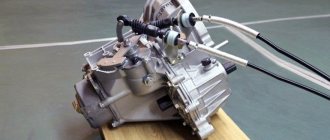
- The engine compartment - the harness combines all the elements of the wires located in the area of the engine and main instruments.
- Salon module. The design is further divided into zones that provide for the connection of individual parts of the wiring.
- Instrument panel module. All elements coming from sensors, instruments and indicators are concentrated here.
- The rear harness is located in the rear of the car and is responsible for supplying power to the lighting, lock and instrument modules.
All the given transcripts are taken from the manufacturer’s official instructions and fully comply with the factory designations and the standard version diagram.
Grant's electrical circuit responsible for the engine compartment
Here are the main parts of the Lada Granta wiring, which are responsible for the normal operation of the power plant:
- 1 – power supply to the headlight, front right;
- 2 – power supply for windshield washers;
- 3 – voltage to the left side of the head optics;
- 5 – on-board power supply;
- 6 – head fuse block;
- 7 – generator;
- 8 – horn;
- 9-11 – terminal blocks to the dashboard;
- 12 – contact pair of rear headlights;
- 13 – main radiator fan drive.
Stories from our readers
“Fucking basin. "
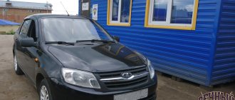
Hi all! My name is Mikhail, now I’ll tell you a story about how I managed to exchange my two-wheeler for a 2010 Camry. It all started with the fact that I began to be wildly irritated by the breakdowns of the two-wheeler, it seemed like nothing serious was broken, but damn it, there were so many little things that really started to irritate me. This is where the idea arose that it was time to change the car to a foreign car. The choice fell on the melting Camry of the tenth years.
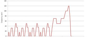
Yes, I had matured morally, but financially I just couldn’t handle it. I’ll say right away that I am against loans and taking a car, especially not a new one, on credit is unreasonable. My salary is 24k a month, so collecting 600-700 thousand is almost impossible for me. I started looking for different ways to make money on the Internet. You can’t imagine how many scams there are, what I haven’t tried: sports betting, network marketing, and even the volcano casino, where I successfully lost about 10 thousand ((The only direction in which it seemed to me that I could make money was currency trading on the stock exchange, they call it Forex. But when I started delving into it, I realized that it was very difficult for me. I continued to dig further and came across binary options. The essence is the same as in Forex, but it’s much easier to understand. I started reading forums, studying trading strategies. I tried it on a demo account, then opened a real account. To be honest, I didn’t manage to start earning money right away, until I understood all the mechanics of options, I lost about 3,000 rubles, but as it turned out, it was a precious experience. Now I earn 5-7 thousand rubles a day. I managed to get the car buy after half a year, but in my opinion this is a good result, and it’s not about the car, my life has changed, I naturally quit my job, I have more free time for myself and my family. You’ll laugh, but I work directly on the phone)) If If you want to change your life like me, then here’s what I advise you to do right now: 1. Register on the site 2. Practice on a Demo account (it’s free). 3. As soon as you get something on the Demo account, top up your REAL ACCOUNT and go to REAL MONEY! I also advise you to download the application to your phone, it’s much more convenient to work from your phone. Download here.
Connection diagram:
This modification will require about 1000 rubles, but it’s worth it! Let us remind you that instead of the standard lock, the “tens” also install a trunk lock from the Lada Kalina, but such a modernization will require more effort and time. By the way, do you know how to implement automatic closing of the trunk lid?
Is it worth installing an electric lock from a Lada Granta on a VAZ?
Many car enthusiasts who independently “pump” their cars are wondering: how to properly connect the electrics? This question arises in almost any installation. After all, simply screwing on the blocks, locks and strips is not difficult, but only properly connected electricians can make the system work. If we take into account one of the most pressing problems - the installation of remote control locks for the fifth door, then the correct wiring diagram for the electric trunk lock will help us here. You can find it either in the instructions that should be included with the device, or you can take it from a reliable source, but it is better to use proven options and ask friends and acquaintances what scheme they used.
Lada Granta diagram - ignition part
- 1 – indicator of lubricant pressure in the crankcase of the power plant;
- 2 – generator connector;
- 3 – power supply to the fuel mixture supply valve;
- 4 – cooling system thermometer;
- 5 – sending a signal to the dashboard;
- 6 – adsorber purge;
- 7 – speedometer;
- 8 – mass air flow sensor;
- 9 – DPKV;
- 10 – DC in front of the catalyst;
- 11 – control pulse device;
- 12 – oxygen concentration sensor in exhaust gases;
- 13/14 – coil and spark plugs, respectively;
- 15 – injector drivers;
- 16 – ignition contact group;
- 17 – detonation measurement sensor.
Grant instrument pinout - dashboard diagram
This part is the most difficult. The large number of pins and the miniature size of the terminals greatly complicates the search for the required group:
- 1/2 – connecting blocks for the front electrical harness;
- 3/4 – similar for the feed harness;
- 5 – lighting control unit;
- 6 – ignition switch module;
- 7 – on-board computer;
- 8 – lever for switching the position of the wipers;
- 9 – tidy;
- 10 – control of emergency modes;
- 11 – cargo compartment lid lock;
- 12 – diagnostic connector;
- 13 – block for the air intake drive;
- 14 – button to turn off the heated rear windshield;
- 15 – emergency contact;
- 16 – brake light switch;
- 17/18 – contact group – output to radio equipment (radio tape recorder);
- 19 – rotating equipment module;
- 20/41 – driver/passenger airbag drive;
- 21 – horn power supply;
- 22 – mounting block group;
- 24 – cigarette lighter group;
- 25 – backlight for stove control;
- 26 – interior lamp;
- 27 – contact group of the ignition switch;
- 28 – controller;
- 29 – incoming connector to the rear of the on-board network;
- 30 – electronic part of the gas pedal;
- 31 – additional resistor;
- 32 – stove motor;
- 33 – heater switch block;
- 34 – door lock module;
- 35/36 – cooling system head fan relay;
- 37 – compressor relay wiring;
- 38 – additional relay or reverse indication coil;
- 39 – air conditioner switch button;
- 40 – automatic transmission drive;
- 42 – evaporator thermometer;
- 43 – output to the rear wiring harness.
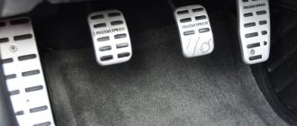
Switches and levers under the steering wheel
The right switch under the steering wheel is responsible for the window cleaner and washer. The switch turns on electrical circuits when the ignition is on. The switch lever can be moved to the following positions
0 – windshield wiper and washer off
1 – intermittent wiper operation mode is on (non-fixed position)
2 – intermittent wiper operation mode is turned on (fixed position). In intermittent operating mode, the windshield wiper blades make one stroke at regular intervals of several seconds, regardless of the presence of drops on the windshield (in a variant, an automatic wiper control system is installed
3 – low speed windshield wiper enabled
4 – high speed windshield wiper enabled
5 – by moving the lever towards you, the windshield washer is turned on (not a fixed position)
Grant ECU pinout
The Lada Granta uses two types of electronic engine control units. Fundamentally, the systems differ slightly, which excludes the possibility of their interchangeability.
| Contact | 11183-1411020-51/52 | 11186-1411020-21/22 |
| A1 | DPKV | |
| A2 | Not involved | |
| A3 | Entering the first knock sensor | |
| A4 | Not used | |
| IN 1 | DPKV | |
| AT 2 | Not involved | |
| AT 3 | Input of the second knock sensor | |
| AT 4 | Main relay output | Not used |
| C1 | Empty | |
| C2 | DTV | |
| C3 | Mass air flow sensor | |
| C4 | UDC | |
| D1 | DDC weight | |
| D2 | Empty | |
| D3 | DTOZH | |
| D4 | Not applicable | |
| E1 | Zeroing the TPS | |
| E2 | Empty | CAN L |
| E3 | Empty | CAN H |
| E4 | Canister purge valve output | |
| F1 | Body from DTV | |
| F2 | Speedometer input | |
| F3 | Not applicable | DFM |
| F4/G4/H4/J4 | Output from injector No. 1/2/3/4 | |
| G1 | Antifreeze temperature sensor ground | |
| G2/G3 | Not used | |
| H1 | On-board electronics grounding | |
| H2 | UDC | |
| H3 | Not involved | Battery charge indicator output |
| J1 | Terminal No. 15 from the ignition switch | empty |
| J2 | Entrance No. 2 TPS | |
| J3 | DDC | |
| K1 | Supplying voltage to the TPS | |
| K2 | Entrance No. 1 TPS | |
| K3 | UDC | |
| K4 | DDK heater power connector | |
| L1/M1 | Leads to the ignition coil ¼ and 2/3 cylinders respectively | |
| L2/M2; L3/M3 | Not involved | |
| L4/M4 | Throttle actuator pin 5/6 | |
Self-installation
First of all, it is necessary to secure the electric drive to the trunk lid and provide it with a mechanical connection to the lock itself. To do this, you will have to make two cuts on the lock, and bend the resulting free “tongue”. Thus, we gained access directly to that part of the lock, by pulling which the trunk lid will open. Now we attach the long metal stick from the kit so that the lock can close when the system is operating. It is quite possible that you will have to cut off extra centimeters of this pin.
Now our device is installed properly and all that remains is to connect the electrics. To do this, we will use the diagram below.
Important! When working with electrical equipment, remove the battery!
In most cars, electrics operate on 12V positive voltage. However, if you doubt that everything is the same for you, it is better to check with the car dealer and not use this diagram for connection. It is very important to make the correct connection of the wires, since the proper operation of your car as a whole depends on it. At best, some options will simply not work correctly; at worst, a short circuit will occur. And it is not always possible to restore the electrics and electronics of the car after it. And this work will cost a lot of money. In addition to the above, lay wires where standard wiring is already laid. In difficult places, for example, when you have to pull the wire from the passenger compartment to the trunk, it is necessary to use protective corrugated tubes.
Electrical work
To begin with, according to the diagram, we connect all the elements located in the trunk. Now you need to tighten the wires to the driver's door. It all depends on the car model. For some it will be convenient to pull the electrics through the door sills from below, for others the option of protective strips from above is suitable. Immediately secure the wires with cable ties. If the length is not enough, take an additional wire, solder the joint with a soldering iron and rewind it with tape. Let's continue connecting. We connect the negative wire to the electric drive, and then connect the second negative wire to the main control relay. The third, also known as the last wire, needs to be connected to the alarm. To do this, you need to find the control unit; most likely, it is located under the dashboard. In it you will find free contacts for connection.
We check, find the negative one and connect. These are the last steps we need to complete. After this, we return the battery to its place and check the functionality of the system. There are cases when the lock does not have enough traction to close. In this option, it is enough to install an additional spring for the lock and the problem should be eliminated. There is one more point that we have not covered - the remote control button. Installation is very simple, and the connection method is described in the same diagram above. You can use absolutely any analogue for the button, even from power windows. And the location also depends solely on your preferences.
Grant relay diagram
Relay location in the main mounting block located in the engine compartment:
- 1 – drive of the cooler of the cooling system;
- 2 – central locking protection;
- 3 – secondary starter relay;
- 4 – additional part of the relay;
- 5 – turn signal and emergency signal breaker relay;
- 6 – wiper drive protection;
- 7/9 – insertion of high/low headlight modes;
- 8 – horn protection element;
- 10 – heated aft windshield;
- 11 – main relay block;
- 12 – fuel pump relay.
Push-button switch block
Depending on the configuration, the following switches are installed in the unit: a heated windshield switch, a heated rear window switch. The rear window defroster only works when the ignition switch is in position “I”. When you press the switch button, the rear window heating is turned on and the warning light in the button lights up. When pressed again, the heating turns off. When the key in the ignition switch is turned to position “0” while the heater is on, the heating function is turned off. When the engine is restarted, the heating function is restored without additional pressing of the switch button. The indicator located on the switch button will light yellow during the entire time the heater is operating.
Detailed diagram of the VAZ Grant (dashboard)
The vehicle is supplied to the market with a 32-pin instrument panel as standard. The standard pinout of the Grant shield has only 26 pins involved. Residual connectors are provided for the possibility of adding equipment or custom modifications:
- 1 – to the low oil pressure sensor in the engine crankcase;
- 2 – to the handbrake indication switch;
- 3 – intended for service needs when diagnosing the instrument panel;
- 4 – to external lighting switches;
- 5/6 – similar for right and left turn signals, respectively;
- 7/8 – CAN L/H;
- 9 – indication of seat belt position;
- 10 – contact of the Reset button of the steering column lever;
- 11 – response of the brake fluid reservoir sensor;
- 12/13 – on the head optics, high/low beam position;
- 14/15 – foglight terminals front/rear, respectively;
- 16/18 – receiving immobilizer antenna signal;
- 17 – ground wire of the instrument panel;
- 19/21 – to terminal No. 30/15;
- 20 – for the drive of the electric power steering unit;
- 22 – for door closing sensors;
- 23/24 – MK buttons for forward and reverse, respectively;
- 25 – for an environmental thermometer;
- 26 – gas tank float indication.
Additional modernization of locks
If you dream of your car doors opening and closing as smoothly as in foreign cars, try installing silent locks. Such a device can be installed on any model of Zhiguli. For representatives of the retro era, such modernization is also possible, but the locks themselves will have to be filed a little. By the way, you can also put it on the trunk. In general, there is no limit to perfection.
And the installation is, in truth, very simple and transparent. It is enough to dismantle the old locks, try not to drop the necessary elements inside the door, or remove the trim in advance. And then install new analogues on two bolts. There are situations when, after installation, the door does not close tightly or warps slightly, causing cracks to form. Solving the problem is also very simple by adjusting the location of the device. In general, initially try to secure it exactly where the old one was.
Lada Granta: wiring diagram for rear wiring harness devices
The rear part of the car wiring is responsible for the equipment of the stern and sides of the car. all additional equipment is connected exclusively through this part of the highways:
- 1/2 – contact group for the dashboard;
- 3/4 – direction indicators;
- 5 – handbrake indicator;
- 6 – rear window heating contact;
- 7 – interior lamp;
- 8 – indicator of the driver’s seat belt position;
- 9 – cargo compartment illumination lamp;
- 10 – fuel pump drive;
- 11/15 – aft dimensions for the left and right sides;
- 12 – trunk lid lock drive;
- 13 – button for turning on the interior lamp;
- 14 – additional stop chain;
- 16-19 – door terminal blocks for the rear left, rear right, front left and front right doors;
- 20 – airbag control drive;
- 21 – contact group of license plate lights;
- 22 – on the dashboard;
- 23/24 – rear speed indicator sensors;
- 25/26 – seat belt pretensioners;
- 27 – group of dashboard contacts.
All services for Lada Granta
- Body repair Lada Granta Body repair Lada Granta
Painting Lada Granta Painting Lada Granta Painting the rear wing Lada Granta Painting the front wing Lada Granta Painting the front bumper Lada Granta Painting the rear bumper Lada Granta Painting the front door Lada Granta Painting the rear door Lada Granta Painting the hood Lada Granta Painting the tailgate Lada Granta Painting the roof Lada Granta Painting Lada Granta body Painting of Lada Granta frame Painting of Lada Granta front spar Painting of Lada Granta rear spar Painting of Lada Granta threshold Painting of Lada Granta radiator grille Painting of Lada Granta side mirror Mechanical repair of Lada Granta
- Mechanical repair of Lada Granta
Suspension and steering of Lada Granta Armature work of Lada Granta Replacement of glass of Lada Granta Brake system of Lada Granta Gearbox of Lada Granta Car diagnostics of Lada Granta Engine repair of Lada Granta Local repair of Lada Granta Electrical repair of Lada Granta Chassis repair of Lada Granta Maintenance maintenance of Lada Granta
- Maintenance service Lada Granta
Changing Lada Granta oil Replacing Lada Granta pads Replacing Lada Granta filters
Preventive measures
In order for the factory wiring of the Lada Grant to serve for a long time and not break, experienced experts strongly recommend following a number of simple rules.
- Periodically check all contact connectors and terminals for oxidation and rust. Such damage to the connections can cause a short circuit and a critical decrease in the conductivity of the line, which is perceived by the on-board computer as an error or breakdown.
- Use only original consumables and electronic components. The use of counterfeit products does not guarantee the functionality of the circuit. At the same time, some elements, when damaged, cause a voltage drop in the network, which becomes a direct cause of failure of other equipment or a fire.
- Use special oil to treat contact groups. The fluid is sold in auto shops or electronics stores. After treatment, the contacts are covered with a moisture-impermeable layer, which increases their service life by 2-3 times.
- Carefully monitor the charge level and condition of the battery. The wiring of the Lada Granta critically perceives a significant voltage drop in the on-board circuits. As a result, this may cause damage to the firmware of electronic control units.
Downloading a book
After successfully completing the payment (by any method) and returning to the KrutilVertel store from the payment system website, you will be taken to the successful payment page:
The book you purchased will be in your personal account, from where you can always download it.
Please note that after making the payment, you need to return back from the payment system website to the KrutilVertel website. If for some reason you did not return back to the site and closed the payment system tab with a message about the successful completion of the payment, please let us know - we will send you a letter indicating access to download the book
If for some reason you did not return back to the site and closed the payment system tab with a message about the successful completion of the payment, please let us know - we will send you a letter indicating access to download the book.