Causes of error P0560
The most common causes of the P0560 code are:
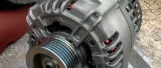
- Generator malfunction
- Battery malfunction
- Malfunction of the starting system or charging system
- Wire damage
- Damaged battery cables
- Voltage regulator malfunction
- Battery terminal corrosion
- The presence of other malfunctions in the system, which leads to self-discharge of the battery
In very rare cases, the problem may be a faulty PCM.
Determining and decoding errors on the VAZ 2114
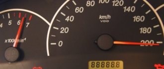
Self-diagnosis of a car allows you to identify faults, but some of them are rarely identified. An odometer is used for diagnostics.
see also
Self-diagnosis of VAZ 2114
The sequence of actions is as follows:
- Press and hold the odometer button and turn the ignition key to the first position.
- Release the odometer button and press briefly again. As a result, the firmware version will be displayed.
- Now, to see the error codes, you need to press and release the odometer button again.
Error codes are in the form of numbers from 1 to 9 and two-digit numbers, unlike those displayed by the on-board computer. Thus, you can use the odometer to identify some car faults. The most common errors are shown in the table below.
VAZ 2114 error code table
| Code | Description of the error |
| 1 | Microprocessor malfunctions |
| 2 | Problems with the fuel level sensor |
| 4 | Exceeding the permissible voltage in the electrical network |
| 8 | Mains voltage too low |
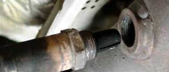
| 13 | No signal from the oxygen sensor |
| 14 | Very high signal level of the coolant temperature sensor |
| 15 | Coolant temperature sensor signal very low |
| 16 | High voltage in the on-board network |
| 17 | Low voltage in the on-board network |
| 19 | Problems with the crankshaft position sensor signal |
| 24 | Malfunctions in the speed sensor |
| 41 | Incorrect phase sensor signals |
| 51, 52 | Problems with the ROM and RAM of the device, respectively |
| 53 | CO potentiometer does not work |
| 61 | Problems with the lambda probe sensor |
Diagnosis of faults using special equipment
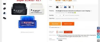
To identify faults, service stations usually use the car’s on-board computer and a laptop with specialized applications. In this case, it is possible to obtain error codes that correspond to various problems. The most common of them are shown in the table.
How does a mechanic diagnose a P0560 trouble code?
After performing a complete inspection, the mechanic will determine when and under what conditions the P0560 code was stored in the vehicle's PCM using an OBD-II scanner. He will then check the battery and replace it if necessary.
The mechanic will also check and, if necessary, replace any worn or damaged cables, wiring, and connectors. The mechanic will then inspect the vehicle again to see if the problem has been resolved. If the problem persists, a mechanic will check the vehicle's PCM.
VAZ fault code P0562
If during two drive cycles the voltage at pin 37 of the controller block is below 9 V, the VAZ P0562 fault code, low voltage of the on-board circuit, is entered into the controller’s memory, and the “Check Engine” lamp lights up on the instrument panel. Before starting troubleshooting, you need to check the voltage in the vehicle's on-board system and at the battery terminals; it should not be lower than 11.5 V. If the car starts, check the voltage output by the generator with the high beam headlights on, which should be within 13.5 - 14 .5 V. If the voltage is not normal, then it is necessary to check the tension of the drive belt or remove and repair the generator. If the voltage of the on-board network corresponds to the norm, it is necessary to find the reason for the appearance of the fault code. To find out the reasons for the appearance, it is necessary to check the condition of the controller's power circuit and its connection to ground. To speed up the process and reduce labor costs, it is advisable to divide the circuit into two parts and first check the voltage value at terminal 87 of the main relay block. The voltage should not differ from the battery voltage by more than 0.5 V. If the voltage does not correspond to the norm, you need to find the place of bad contact by checking the circuit from the battery to the relay, according to the connection diagram. If the voltage at terminal 87 of the main relay is normal, with the ignition on, check for a voltage drop at terminal 30 of the same relay and terminal 37 of the controller block. If the voltage at pin 30 is low, change the relay or eliminate bad contact in the relay block. If there is a voltage drop at pin 37 of the controller block, it is necessary to eliminate an open or broken contact in the circuit from the main relay to the controller, according to the connection diagram. If the voltage supply circuit is working properly, check with a tester one by one, with the ignition on, the voltage between terminals 37 - 19, 37 - 14, 37 - 24. The voltage value should not differ from the battery voltage by more than 0.5 V, otherwise it is necessary to eliminate poor contact where the wires are attached to the negative of the car. When, after performing all the checks and work, the VAZ P0562 fault code remains active, there may be a weak contact in the plug connection of the controller or a malfunction of the controller itself.
admin 28/11/2011
“If you notice an error in the text, please highlight this place with the mouse and press CTRL+ENTER” “If the article was useful to you, share the link to it on social networks”
How serious is P0560?
The P0560 code is quite serious because it can cause problems with the battery or the starting or charging system, which can also affect the functioning of other vehicle systems, such as:
- Security system and locking system
- Acoustic, telephone and navigation systems
- Car entertainment systems
- Electric seat adjustment system
- Air conditioning system (climate control)
Fuel efficiency may also decrease over time. Therefore, if a P0560 code is detected, it is recommended that you contact a qualified technician as soon as possible to diagnose and repair the error.
Lada Kalina error p0481
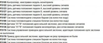
Malfunction code P0100 low signal level of the air flow sensor P0101 high level of the air flow sensor signal P0102 low level of the mass air flow sensor signal P0103 high level of the mass air flow sensor signal P0105 low level of the pressure sensor signal P0106 high level of the pressure sensor signal P0107 low level of the pressure sensor signal P0108 high signal level of the pressure sensor P0110 low signal level of the air temperature sensor P0111 high level of the air temperature sensor signal P0112 low signal level of the air temperature sensor P0113 high level of the air temperature sensor signal P0115 incorrect signal of the coolant temperature sensor P0116 incorrect signal of the coolant temperature sensor P0117 low signal level of the coolant temperature sensor P0118 high signal level of the coolant temperature sensor P0120 low signal level of the throttle position sensor P0121 high signal level of the throttle position sensor P0122 low signal level of the throttle position sensor P0123 high signal level of the throttle position sensor P0130 incorrect signal of the first oxygen sensor P0131 low signal level of the first oxygen sensor P0132 high signal level of the first oxygen sensor P0133 slow response of the first oxygen sensor P0134 lack of signal from the oxygen sensor P0135 malfunction of the heater of the first oxygen sensor P0136 short to ground of the second oxygen sensor P0137 low signal level of the second oxygen sensor P0138 high level signal of the second oxygen sensor P0140 break of the second oxygen sensor P0141 heater malfunction P0171 mixture too lean P0172 mixture too rich P0201 open circuit of the injector control circuit of the first cylinder P0202 open circuit of the control circuit of the injector of the second cylinder P0203 open circuit of the control circuit of the injector of the third cylinder P0204 open circuit of the control circuit of the injector of the fourth cylinder P0217 temperature engine is above the maximum permissible P0219 engine speed is above the maximum permissible P0230 short to ground in the primary circuit of the fuel relay P0231 short to positive in the supply of the primary circuit of the fuel relay P0261 short to ground in the injector control circuit of the first cylinder P0262 short to positive in the supply of the injector control circuit of the first cylinder P0264 short to ground injector control circuit of the second cylinder P0265 short to positive in the power supply of the injector control circuit of the second cylinder P0267 short to ground in the injector control circuit of the third cylinder P0268 short to positive in the supply of the injector control circuit of the third cylinder P0270 short to ground in the injector control circuit of the fourth cylinder P0271 short to positive in the control circuit injector of the fourth cylinder P0300 detected multiple misfires P0301 detected misfires of the first cylinder P0302 detected misfires of the second cylinder P0303 detected misfires of the third cylinder P0304 detected misfires of the fourth cylinder P0327 low signal level of the knock sensor P0328 high level of the knock sensor signal P0335 incorrect signal of the crank position sensor shaft P0337 Crankshaft position sensor short to ground P0338 Crankshaft position sensor open circuit P0336 crankshaft position sensor error P0339 crankshaft position sensor synchronization error P0340 phase sensor error P0341 phase sensor open circuit P0342 low level of camshaft position sensor P0343 high level of position sensor camshaft P0344 camshaft phase sensor synchronization error P0350 short to ground in the ignition coil circuit P0351 open or short to positive in the power supply of the first ignition channel circuit P0352 open or short to positive in the power supply of the second ignition channel circuit P0403 open in the recirculation valve circuit P0404 short to ground or positive in the power supply recirculation valve circuit P0405 low signal level from the recirculation valve position sensor P0406 high signal level from the recirculation valve position sensor P0422 neutralizer efficiency below the threshold P044l incorrect air flow through the purge valve P0443 malfunction of the canister purge valve control circuit P0444 short to positive power or open valve control circuit canister purge P0445 short to ground of the canister purge valve control circuit P0480 faulty cooling fan relay control circuit P0481 faulty second cooling fan relay control circuit P0500 incorrect vehicle speed sensor signal P0501 incorrect vehicle speed sensor signal P0503 intermittent vehicle speed sensor signal P0505 idle speed control error P0506 low idle speed P0507 high idle speed P0560 incorrect on-board network voltage P0562 low on-board network voltage P0563 high on-board network voltage P0601 ROM error P0603 RAM error P0604 internal RAM error P0606 fatal control controller malfunction P0607 incorrect controller detonation channel signal P0615 Control circuit starter open P0616 Starter control circuit short to ground P0617 Starter control circuit short to +12 P0650 short to ground or to positive power supply of the CHECK ENGINE lamp circuit P0651 Short to power supply of the CHECK ENGINE lamp circuit P0654 short to ground or to positive power supply of the tachometer signal circuit P0655 Short to Tachometer signal circuit power supply P1102 Oxygen sensor heater resistance low P1115 Oxygen sensor heater control circuit faulty P1123 Idle rich P1124 Idle lean P1127 Part load rich P1128 Part load lean P1135 Sensor heater circuit faulty oxygen then the converter P1136 rich mixture in light load mode P1137 lean mixture in light load mode P1140 incorrect signal from the mass air flow sensor P1141 The oxygen sensor heater circuit after the converter is open, short to ground or to + 12V P1170 low or high signal level from the CO correction potentiometer P1171 low signal level of the CO potentiometer P1172 high signal level of the CO potentiometer P1230 short to ground or to positive power supply of the primary circuit of the main relay P1231 Short to power supply of the primary circuit of the main relay P1386 malfunction of the detonation detection channel P1410 short to positive power supply of the canister purge control circuit P1425 short to ground canister purge control circuit P1426 open canister purge control circuit P1500 open circuit of the electric fuel pump relay control circuit P1501 short to ground of the electric fuel pump relay control circuit P1502 short to positive power supply of the electric fuel pump relay control circuit P1509 overload of the idle speed regulator control circuit P1513 short to ground of the idle air regulator control circuit P1 514 open circuit or short to positive power supply of the idle speed regulator control circuit P1530 short circuit to ground or positive supply of the primary circuit of the air conditioner relay P1531 short circuit to power of the primary circuit of the air conditioner relay P1541 open circuit of the fuel pump relay control circuit P1570 incorrect signal from the APS P1600 no connection with the APS P1602 loss of on-board voltage network in the controller P1603 EEPROM error P1606 incorrect signal from rough road sensor P1607 low signal level from rough road sensor P1612 processor reset error P1616 Rough road sensor. Low signal P1617 high signal level of rough road sensor P1620 ROM error P1621 RAM error PI622 ROM error P1640 EEPROM test error P1689 erroneous code values in the controller error memory Taken from: https://carslada.ru.
What repairs can fix the P0560 code?
To resolve the P0560 code you may need to:
- Replacing the battery
- Generator replacement
- Repair or replacement of wires, cables and connectors
Some vehicles may experience problems with the PCM or charging and starting systems. In this case, more serious repairs or replacement of the above systems may be required.
Additional comments for troubleshooting P0560
Before replacing any parts, it is necessary to perform a thorough diagnosis and consider all possible causes of the error. After replacing the required part, it is necessary to check the integrity of all system circuits and carefully inspect the vehicle to ensure the successful completion of the repair work.
What to do if error P0130 occurs
As you can understand from the description of the problem, there are not many factors that lead to error P0130. Accordingly, the driver or technician can get rid of the malfunction by performing the following algorithm of actions to determine the cause of the problem and eliminate it:
The first step is to check the wires that supply the first lambda probe (installed before the catalyst);
Depending on what problem was identified during the diagnosis, it is necessary to carry out the appropriate repair work:
If there are problems with the wiring: find the break point and fix the problem;
After completing the necessary steps to eliminate the P0130 error, you should let the engine run for some time in various modes (especially those in which the Check Engine light came on) and reset the error.
Most often, error P0130 is diagnosed on Opel, Kia, Hyundai, Subaru and Ford vehicles.
( 435 votes, average: 4.55 out of 5)
Related Posts
Error P0135 – oxygen sensor heating power supply circuit open
Error P0380 - Glow Plug Circuit Malfunction
Troubleshooting
When a P0500 code appears, it potentially points to several sources of problems. It could be:
- the speed sensor itself;
- dashboard electronics;
- ECU.
Before you begin diagnostics and repairs, make sure that the problem is not with the speedometer itself. It's easy to do. You just need to do a test drive.
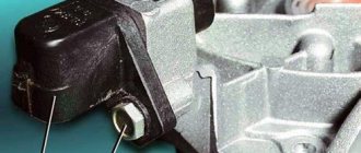
Speed sensor for car
If the diagnostic scanner shows a P0500 error, you need to do the following:
- Using diagnostic equipment, check the operation of the speed sensor. Not everyone has special equipment in their garage. Therefore, the easiest way is to connect a known-good controller. If the error does not go away after resetting, continue searching.
- Using a multimeter, check the circuit between the input signal and ground, or the power wire, for a short circuit. Due to broken insulation, a short circuit quite often occurs, and the system ceases to function correctly.
- Check the connection between the controller and its ground.
- If you have a sensor with 4 wires on your car, you should check the integrity of the latter with a multimeter.
Please note that communication with the sensor will be interrupted when the car is stationary. Therefore, in this case, the diagnosis is performed while moving. It can be imitated by hanging the drive wheels.
Next, follow this algorithm:
- connect the laptop with diagnostic software to the vehicle diagnostic connector;
- turn on the ignition and run the test programs;
- select the speed display item;
- start driving so that the wheels rotate;
- compare the speed readings on the laptop and on the speedometer;
- if the parameters match, just reset the error, most likely this is an accident;
- if the readings are different, check the voltage in the dashboard;
- Next, the contacts and wiring going from the sensor to the ECU are checked;
- Since occasionally the speed sensor itself also fails, it should be checked with a multimeter for resistance and voltage.
Practice shows that most often the reason lies in a violation of the integrity of the insulation and short circuits. Or the sensor does not fit tightly enough to the contacts, which causes the accuracy of the transmitted signal to be impaired.
How to troubleshoot P0134?
Before attempting to electrically diagnose the P0134 code, ensure that the engine is running and that there are no air leaks or serious exhaust leaks that could affect the operation of the oxygen sensors.
Also, make sure there are no rich or lean conditions and that the engine oil is not contaminated with antifreeze. If any other codes are present along with P0134, troubleshoot those issues first before attempting to diagnose P0134.
In a properly functioning oxygen sensor, any change in throttle will result in an almost immediate change in signal voltage. However, the speed at which changes occur (depending on the efficiency of the sensor) is best assessed using an oscilloscope.
Keep in mind that while an oscilloscope can identify emerging problems, interpreting the resulting waveforms requires expert knowledge and verified reference data for each vehicle being tested.
Therefore, in order to identify a faulty DC (if there is no oscilloscope), it should be enough that there are no changes in the signal voltage during a discernible period.
Step 1
Take a diagnostic scanner or adapter and read the information from the car. Record all stored trouble codes and available freeze frame data. This data can be useful if an intermittent error is later diagnosed.
Step 2
Visually inspect all wiring associated with the damaged sensor. Look for burnt, shorted, or otherwise damaged wires and connectors. Restore them if required.
Step 3
If there is no visible damage to the wires, check resistance, input (reference) voltage, ground, and continuity in all circuits associated with the damaged sensor.
Before checking the wiring integrity, be sure to disconnect the sensor from the ECU to prevent damage to the controller.
Since the P0134 code indicates a problem in the signal voltage circuit, as opposed to the heater control circuit, pay special attention to the resistance and continuity values in the signal circuit between the ECU connector and the sensor. These values must correspond exactly to those specified in the repair manual.
Try to avoid signal circuit repairs - it is best to always replace the associated harness to avoid problems with poor connections and high resistance that can arise from poorly executed repairs.
Make sure that the sensor is receiving full voltage from the battery. Keep in mind that in some cases the heater circuit voltage comes from the ECU, in which case the circuit is not protected by a fuse. Look in the repair manual to see how voltage is supplied to the DC heater.
Since the sensor has a heated element, it is possible that low battery voltage, poor grounding, or other resistance issues could affect the time it takes for the element to heat up, which is one reason why the code may set. P0134.
It goes without saying that the voltage/condition of the battery should also be checked. However, in cases of low battery voltage, codes related to low input voltages to the heater control circuit may be present along with P0134.
Step 4
If all data obtained is within the manufacturer's specifications, unscrew the oxygen sensor from the exhaust pipe and inspect it for discoloration or the presence of any type of deposits that may reduce the effectiveness of the sensor. In general, the correct color of the oxygen sensor should be the same color as a healthy, properly functioning spark plug.
Compare the sensor to the pictures at the top of this article, but keep in mind that the DC cannot be cleaned of deposits. The only reliable remedy is to replace the sensor rather than use any additives.
If the DC does not show discoloration or deposits, measure the sensor resistance and replace it if its resistance is outside the manufacturer's specifications.
Replacing the sensor does not make sense if it shows signs of “poisoning” with oil or antifreeze. In these cases, the underlying problem must be resolved to prevent the P0134 code and its associated symptoms from recurring.