If the check engine light comes on or problems are noticed in the operation of the vehicle systems, then you can quickly find out the cause using the on-board computer. or high-quality vehicle diagnostics at a service station. The article provides explanations of error codes.
Error Explanation of the error code: 0102 Low signal level of the mass air flow sensor 0103 High level of the mass air flow sensor 0112 Low level of the intake air temperature sensor 0113 High level of the intake air temperature sensor 0115 Incorrect signal of the coolant temperature sensor 0116 Incorrect signal of the coolant temperature sensor 0117 Coolant temperature sensor signal low 0118 Coolant temperature sensor signal high 0122 Throttle position sensor signal low 0123 Throttle position sensor signal high 0130 Oxygen sensor 1 signal incorrect 0131 Oxygen sensor 1 0132 Sensor signal high crankshaft 1 0133 Oxygen sensor 1 response slow 0134 Oxygen sensor 1 signal missing 0135 Oxygen sensor 1 heater fault 0136 to ground 0137 sensor 2 signal low 0138 Oxygen sensor 2 signal high 0140 Oxygen sensor 2 open circuit 0141 Sensor heater fault oxygen 2 0171 Mixture too lean 0172 Mixture too rich 0201 Injector 1 control circuit open Injector 2 control circuit open 0203 control circuit open 0204 Injector 4 control circuit open 0261 Injector 1 circuit short to ground 0264 Injector 2 circuit short to ground 0 267 Short circuit to ground of the injector circuit 3 0270 Short to ground of the injector circuit 4 0262 Short to +12V of the injector 1 circuit 0265 Short to +12V of the injector 2 circuit 0268 Short to +12V of the injector 3 0271 Short to +12V of the injector 4 circuit 0300 Many misfires 0 301 Passes ignition in cylinder 1 0302 Misfire in cylinder 2 0303 Misfire in cylinder 3 0304 Misfire in cylinder 4 0325 Open circuit of knock sensor 0327 Low level of knock sensor signal 0328 High level of knock sensor signal 0335 Incorrect signal from crankshaft position sensor 0336 Signal error position sensor crankshaft 0340 Phase sensor error 0342 Low phase sensor signal 0343 High phase sensor signal 0422 Low converter efficiency 0443 Malfunction of the canister purge valve circuit 0444 Short or open canister purge valve 0445 Short to ground of the canister purge valve 0480 Malfunction cooling fan circuit 1 0500 Invalid signal speed sensor 0501 Incorrect speed sensor signal 0503 Interruption of the speed sensor signal 0505 Idle speed controller error 0506 0507 High idle speed 0560 Incorrect on-board network voltage 0562 Low on - board network voltage 0563 High on-board network voltage 0601 ROM error 0603 External RAM error 0604 Internal RAM Error 0607 Knock Channel Malfunction 1102 Oxygen Sensor Heater Resistance Low 1115 Oxygen Sensor Heater Circuit Faulty 1123 Idle Rich 1124 1127 Part Load Rich 1128 Part Load Lean 1135 Heater Circuit oxygen sensor 1 open, short circuit 1136 Rich mixture in Light Load mode 1137 Lean mixture in Light Load mode 1140 Measured load differs from calculation 1171 CO potentiometer low level 1172 CO potentiometer high level 1386 Knock channel test error 1410 Canister purge valve control circuit short circuit tion at +12V 1425 circuit control circuit of the adsorber gasket short -clicking on Earth 1426 Circuit of control of the Dipling valve of the adsorber valve 1500 breakdown of the control circuit of the tanososa relay 1501 KZ to the mass of the control circuit of the tanososa relay 1502 A short circuit for +12V control circuit 1509 Overloading of the control circuit of the CHIR -COND speed 1513 Idle speed control circuit short circuit to ground 1514 Idle speed control circuit short circuit to +12V, open 1541 Fuel pump relay control circuit open 1570 Incorrect APS signal 1600 No communication with APS 1602 Loss of on-board power supply voltage to the ECU 1603 EEPROM error 160 6 Sensor uneven road incorrect signal 1616 Rough road sensor low signal 1612 ECU reset error 1617 Rough road sensor high signal 1620 EPROM error 1621 RAM 1622 EPROM error 1640 EEPROM Test error 1689 Incorrect error codes 0337 Crankshaft position sensor, short to ground 0338 Crankshaft position sensor, open circuit 0441 Air flow through the valve is incorrect 0481 Malfunction of the cooling fan circuit 2 0615 Starter relay circuit open 0616 Starter relay circuit short circuit to ground 0617 Starter relay circuit short circuit to +12V 1141 Malfunction of the oxygen sensor 1 heater after the neutralizer 230 Malfunction of the fuel pump relay circuit 2 63 Malfunction Injector Driver 1 266 Injector Driver 2 Malfunction 269 Injector Driver 3 Malfunction 272 Injector Driver 4 Malfunction 650 CheckEngine Lamp Circuit Malfunction
Error codes/test for instrument cluster (Kalina/Priora)
Error codes:
From yourself if you do not press any control buttons for about 15-30 seconds. the panel enters the operating state. “Reset” is the one that resets the daily mileage.
Error codes for VAZ 2110 and 2112 (8) 16 valves. Read and save
To find out the error codes on the VAZ 2110 and 2112 (8) 16 valves yourself, it is not enough to know how to use the on-board computer and removable controllers. You must be able to decipher the given indicators. Car diagnostics can be carried out at a service station or at home, having the appropriate equipment. Modern domestic cars are equipped with an on-board computer (OB), which can display system errors on the display.
A more thorough analysis of faults, without visiting a service station, allows you to carry out a removable controller. The need to check the vehicle occurs when the Check indicator lights up.
Decoding standard codes
Error codes for VAZ 2110 and 2112 (8) 16 valves
. which are issued by the ECU of the models in question are indicated by the letter “P” at the beginning and a subsequent set of numbers. Their decoding is as follows:
Injection system error codes have the following meaning (before each value there is a letter “P”):
When signals about malfunctions in the ignition system appear, the following codes are displayed:
Carrying out vehicle diagnostics makes it possible to decipher fault codes in the control relays of various components, road terrain sensors, fuel mixture saturation and some other indicators. The designations are numbered as follows after “P”:
Some decodings for the “January” type controller
When using this device, the readings and their interpretation will look like this:
If desired and with the right approach, timely diagnostics helps to identify malfunctions of various components at an early stage. Error codes for VAZ 2110 and 2112 (8) 16 valves are identical. They can be identified and decrypted using an on-board computer and a connected external controller.
SELF-DIAGNOSTICS OF THE KALINA/PRIORA INSTRUMENT COMBINATION
- With the ignition off, press the “Reset” button (reset daily mileage). While holding the button, turn on the ignition.
- The instrument panel will go into self-diagnosis mode, all segment positions will light up on the display, all indicators will light up, and the arrows will travel the full path.
- Using the control button on the right steering column switch, we switch between modes (self-diagnosis, firmware version, error codes).
- To reset errors, you need to be in error mode and press and hold the “Reset” button for more than 3s.
- The diagnostic mode exits automatically after inactivity for 20-30 seconds.
Decoding error codes in the dashboard:
- 2-increased voltage of the on-board network;
- 3-fuel level sensor error (if a break in the sensor circuit is detected within 20s);
- 4-error of the coolant temperature sensor (if an open circuit of the sensor is detected within 20s);
- 5-outside temperature sensor error (if there are no sensor readings within 20s, indication on the LCD is “-C”);
- 6-engine overheating (the criterion for triggering the acoustic alarm has been met);
- 7-emergency oil pressure (the criterion for triggering the acoustic alarm is met);
- 8-defect of the brake system (the criterion for triggering the acoustic alarm is met);
- The 9-battery is discharged (the criterion for triggering the acoustic alarm is met);
- E-determination of an error in a data packet stored in EEPROM.
Combination
| Description of the breakdown | |
| P0300 | The control unit transmits a signal that there is no spark in all cylinders of the 16-valve car engine. |
| P0326 | Incorrect signal received by the control unit from the knock sensor. It is recommended to perform a more thorough check of the device. |
| P0327 | There is an open or short circuit in the knock sensor circuit. The circuit should be checked. |
| P0335, P0336 | There are errors in the operation of the crankshaft sensor. In addition, such combinations may indicate an incorrect signal coming from the device to the on-board computer. |
| P0337 | The crankshaft position monitoring device shorts to ground. |
| P0338 | There is a short circuit or open circuit in the crankshaft sensor circuit. |
| P0342 | The signal in the headlight sensor circuit is too low |
| P0343 | A too high signal has been detected in the circuit of the same device. |
| P0422 | The neutralizer has broken down; it is recommended to replace the device. |
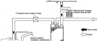
| P0444 | The Lada Priora control unit detected a break in the wiring of the canister valve. |
| P0445 | The canister valve has shorted to ground. |
| P0480 | There is a break in the wiring of the fan relay; the relay should be checked and, if necessary, replaced. |
| P0481 | There is a short circuit in the cooling fan wiring. |
Fault codes for VAZ 2110 2111 2112.
Here we provide only brief information on diagnosing the injection system using the CHECK ENGINE warning lamp. Diagnostics using special instruments and diagnostic cards are described in detail in separate repair manuals for distributed fuel injection systems.
The controller continuously performs self-diagnosis on certain control functions. The controller's language for indicating the source of a malfunction is diagnostic codes. Codes are two-digit numbers ranging from 12 to 61. For different controllers, fault codes may differ slightly from each other. The table “Fault codes for the controller of the “January-4” type” presents a breakdown of the fault codes for the controller of the “January-4” type for the distributed fuel injection system without feedback and with domestic components.
When a malfunction is detected by the controller, the code is stored in memory and the “CHECK ENGINE” indicator light turns on. This does not mean that the engine should be stopped immediately, but the reason for the warning light to come on should be discovered as soon as possible.
Fault codes (errors) of the controller type “January-4”
Indicator lamp diagnostic circuit fault
High signal level of the coolant temperature sensor
Coolant temperature sensor signal low
Increased voltage of the on-board network
Reduced voltage on-board network
Incorrect crankshaft position sensor signal
Throttle position sensor signal voltage too high
Insufficient throttle position sensor signal voltage
There is no signal from the vehicle speed sensor
High signal level of the CO potentiometer
Low signal level of the CO potentiometer
Incorrect signal from the mass air flow sensor (high frequency signal at the sensor output)
Incorrect signal from the mass air flow sensor (low signal frequency at the sensor output)
Idle speed deviation
Invalid knock sensor signal
Programmable read only memory (PROM) error
Controller error (RAM error)
Electrically programmable memory (EPROM) error
Communication error with immobilizer
Error codes for other controllers
Decoding the code Low signal level of the mass air flow sensor High signal level of the mass air flow sensor Low level of the intake air temperature sensor High level of the intake air temperature sensor Incorrect signal of the coolant temperature sensor Incorrect signal of the coolant temperature sensor Low level of the coolant temperature sensor High level of the signal coolant temperature sensor Low throttle position sensor signal High throttle position sensor signal Incorrect oxygen sensor 1 signal Low oxygen sensor 1 signal high crankshaft sensor 1 signal Slow response of oxygen sensor 1 No signal from oxygen sensor 1 Oxygen sensor heater fault 1 Oxygen sensor ground short 2 Oxygen sensor signal low 2 Oxygen sensor signal high 2 Oxygen sensor break 2 Oxygen sensor heater malfunction 2 Mixture too lean Mixture too rich Open injector control circuit 1 Open injector control circuit 2 Open injector control circuit 3 Open injector control circuit 4 Short to ground of injector circuit 1 Short to ground of injector circuit 2 Short to ground of injector circuit 3 Short to ground of injector circuit 4 Short to +12V of injector circuit 1 Short to +12V of injector circuit 2 Short to +12V of injector 3 circuit on +12V injector circuit 4 Many misfires Misfire in cylinder 1 Misfire in cylinder 2 Misfire in cylinder 3 Misfire in cylinder 4 Open knock sensor circuit Low knock sensor signal High knock sensor signal Incorrect crankshaft position sensor signal Signal error crankshaft position sensor Phase sensor error Low level of the phase sensor signal High level of the phase sensor signal Low efficiency of the converter Malfunction of the canister purge valve circuit Short or open circuit of the canister purge valve Short to ground of the canister purge valve Malfunction of the cooling fan 1 circuit Incorrect speed sensor signal Incorrect speed sensor signal Interruption speed sensor signal Idle speed control error Low idle speed High idle speed Incorrect on-board power supply voltage Low on-board power supply voltage High on-board power supply voltage ROM error External RAM error Internal RAM error Knock channel fault Low oxygen sensor heater resistance Faulty oxygen sensor heating circuit Rich mixture in idle mode Lean in idle mode Rich in Part Load mode Lean in Part Load mode Oxygen sensor heater circuit 1 open, short circuit Rich in Light Load mode Lean in Light Load mode Measured load differs from calculation Low level Potentiometer CO High level of potentiometer CO Detonation channel test error Canister purge valve control circuit short circuit to +12V Canister purge valve control circuit short circuit to ground Canister purge valve control circuit open Open fuel pump relay control circuit Short circuit to ground Fuel pump relay control circuit Short circuit to +12V fuel pump relay control circuit Overload of the idle speed regulator control circuit Short circuit to ground Idle speed regulator circuit short circuit to +12V, open Fuel pump relay control circuit open Incorrect APS signal No communication with the APS Loss of on-board power supply voltage to the ECU Error EEPROM Rough road sensor incorrect signal Rough road sensor low signal ECU reset error Rough road sensor high signal EPROM error RAM error EPROM error Test error EEPROM Incorrect error codes Crankshaft position sensor, short to ground Crankshaft position sensor, open circuit Air flow through the valve is incorrect Malfunction cooling fan circuit 2 Starter relay circuit open circuit Starter relay circuit short circuit to ground Starter relay circuit short circuit to +12V Malfunction of the oxygen sensor 1 heater after the converter Malfunction of the fuel pump relay circuit Malfunction of the injector driver 1 Malfunction of the injector driver 2 Malfunction of the injector driver 3 Malfunction of the injector driver 4 CheckEngine Lamp Circuit Malfunction
Without on-board diagnostics (OBD):
- P0105-Damage to the electrical circuit of the air flow meter sensor
- P0112-Low air temperature sensor signal
- P0113-Air temperature sensor signal high
- P0116-Damage to the electrical circuit of the coolant temperature sensor
- P0117-Coolant temperature sensor signal low
- P0118-Coolant temperature sensor signal high
- P0121-Damage to the electrical circuit of the throttle position sensor
- P0122 - Throttle position sensor signal low
- P0123-Throttle position sensor signal high
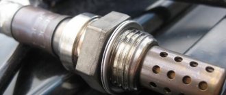
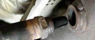
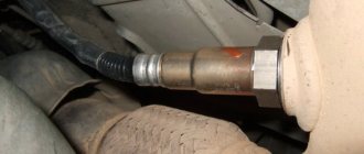
- P0130 - Damage to the electrical circuit of the oxygen sensor
- P0131-Oxygen sensor signal low
- P0132-Oxygen sensor signal high
- P0133 - Oxygen sensor slow response
- P0134 - Oxygen sensor performance low
- P0135-Damage to the electrical circuit of the heated oxygen sensor
- P0230-Damage to the fuel system electrical circuit
- P0201-Damage to the electrical circuit of the fuel injector of cylinder 1
- P0202-Damage to the electrical circuit of the fuel injector of cylinder 2
- P0203-Damage to the electrical circuit of the fuel injector of cylinder 3
- P0204-Damage to the electrical circuit of the fuel injector of cylinder 4
- P0326-Damage to the electrical circuit of the knock sensor
- P0335-Damage to the electrical circuit of the crankshaft angle sensor
- P0336-Random malfunction of the crankshaft angle sensor
- P0342-Camshaft position sensor signal low
- P0343-Camshaft position sensor signal high
- P0501-Damage to the electrical circuit of the vehicle speed sensor
- P0506-Reduced idle speed
- P0507-Increased crankshaft speed at idle
- P0562-Undervoltage in the vehicle's on-board network
- P0563-Increased voltage in the vehicle’s on-board network
- P0606-ECM internal damage
- P1123-Rich fuel mixture
- P1124 - Fuel mixture lean
- P1127-Long-term over-enrichment of the fuel mixture
- P1128-Long-term leanness of the fuel mixture
- P1510 - The idle air system valve is constantly open due to a short circuit in the valve coil power supply circuit.
- P1513-The idle air system valve is constantly open due to an open circuit in the valve coil power supply
- P1552 - The idle air system valve is constantly closed due to the valve coil power supply circuit being shorted
- P1553-The idle air system valve is constantly closed due to an open circuit in the valve coil power supply
- P1586 - Inappropriate signal received from transmission
- P1610-Damage to SMATRA immobilizer
- P1800-Damage to the immobilizer antenna
- P1801-Damage to immobilizer pulse transceiver
- P1803-ECM signal error
- P1805-EEPROM Damage
- P1765 - Torque reduction circuit damage
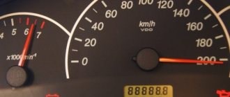
Error codes for the VDO combination on the instrument panel of the VAZ 2110
To be honest, these fault codes are not particularly useful. If we compare it with the readings of special on-board computers, such as STAT, then there is, of course, tens of times more useful information and various data. But we’ll talk about this sometime in future articles.
Car: VAZ-2112. Asked by: Maxim Perepelkin. The essence of the question: How to decipher error codes on the instrument panel of a VAZ-2112?
Good day, please help me understand my situation, or more precisely, the error codes on the instrument panel. No matter how much I try, nothing comes of it, everything is somehow too complicated for me, I don’t understand the Internet well enough to find it, but then a friend recommended your site, they say you will find everything there and if you need anything, they will personally help you.
So I decided to ask this question, I hope for a complete schedule of each code and what it is responsible for, so that I could look at it, so to speak, and understand what’s what, and not sit like I did and think, what the hell is this and why. Traveling constantly for diagnostics turns out to be very expensive, thanks in advance.
How to diagnose the error?
There are two options for diagnosing a VAZ car - testing using the instrument panel and using a computer. The second option is considered more accurate, but its implementation will require a special program and a cable for connecting to the diagnostic connector.
Checking using a computer is done like this:
- The diagnostic wire is connected to the laptop. Its second end must be connected to the OBD2 connector in the Lada car. The location of this block differs depending on the car model; this nuance must be clarified in the service manual.
- A diagnostic program is launched on the computer, which allows you to decipher error codes. To start the test, press the corresponding button.
- The diagnostic process begins. Depending on the utility, the program can separately check the operation of the engine, transmission or electronics.
- After the test is completed, combinations of faults will appear on the computer screen that need to be deciphered. Depending on the program, a description of the error may also be displayed immediately.
What does the error consist of?
The first character means:
The second character in the code means:
The third character identifies the system in which the problem is detected:
The last two characters are a number that corresponds to the error number in the OBD system.
When malfunctions occur in the operation of the engine or other systems, the “Check Engine” indicator is always on on the VAZ dashboard. Its presence may be due not only to a malfunction of the power unit, but also to problems with the wiring or poor contact of one of the sensors.
Excerpt from open sources
2 - Excessive voltage.3 - Fuel level sensor error*.4 - Coolant temperature sensor error*.5 - Outside temperature sensor error**.6 - Engine overheating***.7 - Emergency oil pressure***.8 - Brake defect***.9 - Low battery***.E - Recognition of an error in the data packet stored in the EEPROM.
Note:* – an error is registered if within 20 seconds. a sensor break is recognized;** – an error is registered if within 20 sec. The actual sensor data is not recognized (indication on the LCD is “— °C”);*** – accompanied by an acoustic signaling device.
Table with errors
Sensor malfunctions
To check the flow meter, perform the following steps:
Engine malfunctions
Possible causes of the problem:
If replacing the fuel does not help, it is necessary to diagnose the air intake system. You should tighten the fastening clamps, change the air filter element and check the pressure in the rail (the normalized value is no more than 2.8 atm).
It is also necessary to perform diagnostics:
Diagnostics of high-voltage wires is carried out using a tester; it is necessary to check the resistance. If the obtained value is more than 10 kOhm, then the cables must be replaced. You also need to check the integrity of the spark plugs and make sure there is no carbon deposits on their tips.
If the described actions do not help determine the cause, the cylinders are diagnosed. The user needs to check the compression level, which should be approximately the same in each device. If the obtained values differ by more than 0.5 atm, then the power unit needs to be tested in more detail.
Possible causes of the problem:
To fix the problem, you can try to relearn the throttle valve, to do this, perform the following steps:
Possible solutions to the problem:
Electrical faults
When this combination appears, the following problems are possible:
Possible signs of problems:
Detailed diagnostics of the microprocessor module and its flashing if necessary are required.
If you do not have the appropriate equipment and skills, you can follow these steps to resolve:
Self-diagnosis errors
Three-digit combinations
The appearance of this code may be due to the following conditions:
Composite Combinations
What to do when error P1602 appears: DIY diagnostics
It is clear that with such an error code it is necessary to look for poor contact in the engine control system circuits. True, the direction of the search is not entirely clear and it depends on the symptoms. Therefore, we can only assume what can happen to the electrical system of a VAZ injection engine with error P1602, based on reviews from owners and personal experience:
- No contact at the negative terminal battery It's easy to check. We remove the terminal, assess its condition, if necessary, clean the terminal and terminal, and lubricate it with a special conductive lubricant with an anti-oxidative effect.
- Lack of contact at the negative wire of the battery at the point of connection to the body . We unscrew the wire from the body, carefully clean the terminal and the attachment point, install the terminal in place, carefully screwing it into place with clean fasteners.
- No contact on electronic control unit board . Here the situation is more complicated, since for diagnostics you need to have at least basic knowledge in the field of electronic systems and circuitry.
First, we inspect the ECU contacts, if necessary, clean them, as well as the terminals on the block. After this, you can open the block and visually inspect the board. If there is a loose solder on the board, solder it with a low-power soldering iron, being careful not to overheat the elements. In some cases, warming up the board with a hairdryer helps, but this is a temporary measure. - No contact on the generator . The contact may be damaged either on the power wire or on the signal wire. In both cases, the generator may not charge the battery.
Alternatively, you can remove the generator and check (clean) the contact of its housing with the cylinder block. In some cases this works. - In some cases, periodically power supply to the electronic control unit is lost engine. In these cases, either the fuse may be to blame (depending on the VAZ model, it may have different designations). We check the fuse, as well as the contacts of the mounting block.
Practice shows that these main reasons are the reason for the occurrence of error code P1602 on VAZ cars with an injection engine.
Diagnostics using additional tools
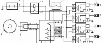
To diagnose cars, including the VAZ 2110, various equipment is used, which is connected to a special connector. Thanks to this equipment, which is not particularly complicated or expensive, you can get a complete picture of the condition of the car.
The service station uses a personal computer to which data from phase sensors is transmitted via a special cable.
Adapter for car diagnostics
Bluetooth devices have appeared on the market that allow diagnostics using a smartphone, tablet or laptop.
They work according to the scheme. The device is connected to the connector, the ignition is turned on and the diagnostic process begins. The data comes from phase sensors to the ECU. From it to a mobile device on which specialized software must first be installed.
This makes it possible not only to obtain more data, but also to present it in a more visual form. This method allows a driver, even with little experience in operating a car (in our case, a VAZ 2110), to obtain all the data about his car.
But most drivers prefer to carry out diagnostics at a service station. So that you are aware of the data that the on-board computer produces through RAM from the phase sensors, we will present the transcripts of common errors.
Decoding combinations
If problems arise with electrical equipment, they must be corrected immediately. Error code 1602 will indicate that not everything is in order in this matter.
Sometimes error 1602 can simply be reset and does not appear in the future. Socialists call such data “good.”
Error 1602 sometimes appears if:
- the battery was disconnected for some time;
- there was a voltage surge when starting the engine, for example, in cold weather.
But if error code 1602 appears all the time, you need to check the entire network. Perhaps there is a break. If error code 1602 constantly appears, you can try cleaning the battery terminals. Check if they are securely fastened. Didn't help, error 1602 still appears? Check the circuit. You need to start from the positive terminal of the battery. Start with the electrical fuse and fuse link.
Check the ground of the ECU, TPS. Sometimes it happens that the cause of error code 1602 is an alarm that can block the controller circuit and affect the readings of the phase sensors. In such a situation, you need to file a claim with the company that installed the alarm.
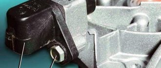
Error 0102 indicates a low signal level, which is reported from the mass air flow phase sensor.
Code 0102 will be stored in RAM memory in the following situations:
- low air consumption, which depends on the speed of rotation of the crankshaft;
- how open the throttle is;
- Several cycles have passed since the problem appeared.
If the error appears periodically, then you need to:
- check the condition of the air barrier;
- fastening the wiring block to the ECU;
- check IAC;
- clean the throttle pipe.
Another error that may occur is 0300. 0300 appears in cases where the RAM detects frequent misfires.
If error code 0300 is displayed constantly, then you need to check the following components:
- spark plug;
- nozzles;
- ignition system;
- increased or decreased compression levels may be the cause of code 0300;
- Also, code 0300 may appear in case of wiring failure.
You cannot ignore the appearance of error 0300. In the future, this may lead to deterioration in the performance of other nodes.
It is not difficult to master car diagnostics, in particular the VAZ 2110. It will extend the service life due to timely detection of faults detected by phase sensors.
Diagnostics using a scanner
The method involves connecting an external computer with the program installed. This opens up more opportunities for car diagnostics. In this case, error codes for VAZ 2110 and VAZ 2112 consist of 5 characters.
- P – failure or malfunction of the power plant, transmission;
- B – body systems are damaged;
- C – a problem has been detected in the vehicle’s chassis;
- U – violation of pairing of different modules.
- 0 – general value;
- 1/2 – manufacturer code;
- 3 – reserve.
- 1-2 – violation in the air-fuel mixture supply devices;
- 3 – malfunction of the ignition units;
- 4 – atmospheric emissions control device;
- 5 – malfunction of the engine speed or engine speed meters;
- 6 – failures in electronics;
- 7-8 – malfunction of the gearbox module;
- 9-0 – reserve unit.
Vehicle electrical malfunctions
The list of faults in the electrical equipment of a car is quite wide. Conventionally, they can be divided into faults of current sources and faults of current consumers. This article discusses malfunctions of current sources.
As you know, the sources of current in a car are the battery and the generator. A malfunction of each current source can immobilize the vehicle at any time.
And if you don’t want to return home on a “tie” or a tow truck, attention must be paid to the technical condition of the battery and generator
In a vehicle's electrical system, the battery and alternator work in tandem. The failure of one leads to the failure of the other. For example, battery malfunctions lead to an increase in the charging current of the generator. Operating the generator in this mode can cause a malfunction of the rectifier unit (diode bridge). On the other hand, a malfunction of the generator voltage regulator is accompanied by an increase in the charging current, which, in turn, leads to systematic recharging of the battery and “boiling off” of the electrolyte.
Battery faults
Battery malfunctions include:
- short circuit between battery electrodes;
- damage to the battery plates;
- cracks in the battery case;
- oxidation of battery terminals.
The main causes of these malfunctions:
- violation of operating rules;
- service life limit;
- manufacturing defects.
Violations of the rules for operating batteries are:
- working with a faulty generator (leads to overcharging or discharging the battery);
- poor contact at the battery terminals (leads to oxidation and destruction of contacts);
- Frequent engine starts or prolonged operation of the starter (leads to deep battery discharge);
- weak fastening of the battery in the engine compartment (leads to mechanical damage to the battery and wires).
The battery can be used effectively for a certain period of time. The average battery life is 3-4 years. With intensive use, as well as operation in harsh climatic conditions, the service life is significantly reduced.
Modern batteries are low-maintenance and maintenance-free. The degree of battery maintenance is determined by the rate of evaporation of water from the electrolyte. For a maintenance-free battery, the critical electrolyte level is reached much later than the end of its service life.
When using rechargeable batteries, you have to deal with manufacturing defects. A faulty battery can be easily replaced under warranty by the seller or manufacturer.
All malfunctions have the same consequence - the battery stops performing its intended function - turning the starter when starting and providing consumers with current when parked. In this case, it is necessary to determine whether the battery needs to be replaced or whether the current source can still serve.
When operating a battery, you must remember that increased discharge at subzero ambient temperatures can lead to freezing of the electrolyte and destruction of the battery case.
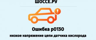
Generator faults
The design of a generator is more complex than that of a battery. Therefore, this device has more malfunctions:
- wear of current collecting brushes;
- damage to the voltage regulator;
- damage to the rectifier (diode bridge);
- wear of the commutator (slip rings);
- wear or destruction of the bearing;
- pulley wear or damage;
- short circuit of the stator winding turns;
- damage to the charging circuit wires.
The main causes of these malfunctions:
- violation of operating rules (long-term operation under heavy load, incorrect polarity when connecting the battery, low tension of the generator belt);
- low quality of components;
- exposure to external factors (moisture, salt, high temperature, dirt);
- service life limit.
Wear or destruction of the bearing is accompanied by increased noise when the generator operates. Other generator malfunctions are diagnosed by low charging current. This is indicated by a warning light on the instrument panel, which lights up periodically or constantly in the event of a malfunction.