Modern car owners independently diagnose certain errors in the car's ECU. The scanner allows you to quickly and accurately identify any problems in systems and indicate further actions to eliminate them.
IMPORTANT! When checking independently with an auto scanner, a driver who encounters error p0130 does not have to contact the service center, but can fix the problem with his own hands. In the overwhelming majority of cases, the causes of this error do not require professional instruments and specialized equipment for repair.
Causes of error P0130
The most common causes of this error are:
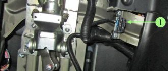
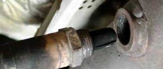
- Disconnecting the oxygen sensor connector
- Corroded oxygen sensor connector
- Damage to the electrical wires coming from the oxygen sensor to the ECM
- Fuel supply limitation (fuel pump malfunction or fuel filter clogged)
- Air intake system leakage
- Air or fuel system leakage
- Malfunction of the mass air flow sensor
- Malfunction of the absolute pressure sensor in the intake manifold
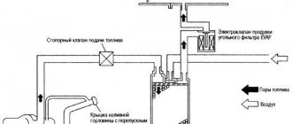
- Malfunction in the fuel vapor recovery system
- Oxygen sensor malfunction
- Fuel pressure regulator malfunction
- Engine control module (ECM) malfunction
Self-diagnosis
In a car, the operation of the entire electronics system is monitored by a control unit (ECU). In order for the driver to recognize operational failures in time and localize them, cars leave the assembly line with an already built-in diagnostic system. It is located on the front panel. With its help, the system itself detects failures in electronic devices and notifies about them, generating errors with digital codes or their combinations. In this way, the car self-diagnosis occurs. To be able to decipher error codes, special tables have been compiled. In this case, self-diagnosis is carried out on the instrument panel, and not on the computer.
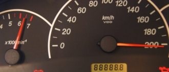
To check, you need to reset the daily mileage data on the wheel revolution meter (odometer), then activate the ignition (position 1).
On all touch devices, the arrows will move twice to the highest readings.
By pressing the odometer button again, messages are received about the installed version of the operating system. The next time you press the button, an indication of problems, if any, is displayed.
What errors may appear during self-diagnosis of the control panel, and how to decipher them
0—indicates that there are no problems with the electrical wiring, apparently the fault is mechanical;
1—indicates malfunctions of the ignition system microprocessor;
2 - no signal is detected coming from the circuit leading to the fuel level sensor. Reason: open circuit, plaque formation due to oxidation of contacts or short circuit;
4—signal of increased voltage in the on-board network (more than 16 V). It is necessary to check the battery and generator;
8—opposite signal, the voltage is too low (less than 8 V) due to a low battery or problems with the generator.
If there is not one malfunction, but a group, then an error is displayed on the dashboard, the code of which consists of several digits resulting from the summation of errors. So, for example, the issued error code 10 indicates errors 2 and 8, 6 – the sum of 2 and 4, 12 – 4 and 8, 14 – 2,4 and 8.
Let's continue decoding:
12 - a malfunction in the circuit leading to the malfunction indicator lamp, possibly due to damage to the connector contacts or their oxidation, or the indicator itself is faulty;
13 - no data is received from the oxygen concentration sensor device (ƛ-probe). The sensor or the wiring leading to it may be faulty;
14—the coolant temperature in the cooling system is higher than normal. Reasons: sensor failure, low fluid level in the radiator, faulty thermostat;
15 - coolant temperature is below normal. Reasons: a failed thermostat, air entering the system due to a coolant leak;
16 - the voltage in the on-board network is too high;
17 - the voltage in the on-board network is too low;
19 - fault in the wiring of the PCV sensor. Reasons: oxidation or contamination of contacts, broken wiring, short circuit, mechanical failure of the wheel;
21-22 - error in the position of the remote sensing sensor, due to a failure of the electronic part, due to a breakdown of the movable core or due to the fact that the coating on the slider has been worn off;
23-25 - deviation from the norm of the intake air temperature sensor. Possible reasons: clogged sensor element, oxidation of contacts, open circuit, short circuit;
24 - the speedometer does not provide reliable data on the vehicle speed. Reasons: the speedometer has mechanical damage, there is contact in the terminal connections, the sensor is faulty, there is a break or a short circuit in the wiring, the computer is malfunctioning;
27-28 - warning about a violation of the level of exhaust gases for one of the reasons: damage to the wiring, the catalytic converter has become unusable, the muffler and muffler suspension are damaged;
33-34 - error code for mass air flow data. Reasons: high voltage in the wiring going to the sensor device, interference affecting the impulse from close proximity of wires or sensor to devices with high voltage (generator, ignition wires, etc.), wear of vacuum and air intake hoses;
35 - malfunctions occur when the engine is idling; they can occur due to a malfunction of the hydraulic compensators in the valve mechanism drive, a malfunction of the TPS, or due to unaccounted for air leaks;
41 - pulse error from the camshaft sensor rarely occurs. Cause: damage to the wiring or malfunction of the sensor itself;
42 - malfunction of the ignition system. Reasons: breakdown of the ignition coil or high-voltage electrical wiring, and possibly incorrect spark plug gap setting;
43 - lack of signal from the detonation sensor device. Reasons: sensor failure, contact oxidation or wiring fault;
44-45 - the stoichiometric combustible mixture is incorrectly formed. Causes: incorrect air/fuel ratio, faulty throttle sensor or oxygen sensor;
49 - the on-board computer registers a loss of vacuum for one of the reasons: loss of tightness of the pipeline or working chambers of the amplifier, failure of the check valve;
51 - an error in the operation of the ROM requires checking the connector, injector harness and all wiring, as well as the ground of the control unit;
52 - there is a problem with the operation of the random access memory, it is necessary to diagnose the microprocessor;
53 — no signal from the exhaust gas controller;
54 - the octane corrector controller does not respond, it is either de-energized or faulty;
55—high engine load. Reasons: damage to the power circuit, violation of the cooling mode of the unit, load on the shaft due to worn bearings, sudden changes in voltage in the wiring;
61 - distorted oxygen sensor data. Causes: sensor malfunction, unreliable connection of the contacts of the controller, sensor and ignition system harness or damage to the harness;
Self-diagnosis does not always accurately display breakdowns. The error code can only indicate the section of the electrical wiring where the malfunction occurred. There may also be software glitches that may cause errors to not always be displayed correctly. To obtain more accurate diagnostic data, you should use external devices (diagnostic scanners, computer diagnostics).
How does a mechanic diagnose a P0130 code?
To properly diagnose the P0130 code, you will need an advanced diagnostic scanner that can not only read stored trouble codes, but also view readings from various sensors in real time.
First, the mechanic reads all the stored data and error codes using an OBD-II scanner to find out when and under what circumstances the P0130 code appeared. He will then clear the error codes from the computer's memory and test drive the vehicle to see if the P0130 code appears again.
If the error code appears again, the mechanic will continue diagnosing to determine the cause of the error. To do this he will need:
- Advanced diagnostic scanner
- Digital voltmeter
- Smoke installation for detecting leaks in the intake system
Common mistakes when diagnosing code P0130
The most common mistake when diagnosing a P0130 code is to rush to replace the oxygen sensor without first checking it.
Before replacing the sensor, it is necessary to perform a thorough diagnosis using special equipment and consider all possible causes of the error.
Since there can be multiple causes for the P0130 code, replacing the sensor may not solve the problem and may cause the code to reappear.
What repairs can fix the P0130 code?
To resolve P0130, you may need to:
- Connecting the OBD-II scanner to the vehicle diagnostic connector
- Checking for an Error Code
- Analysis of data stored in the vehicle's ECM memory
- Clearing error codes from computer memory
- Test drive your vehicle to see if P0130 appears again
- Check and, if necessary, repair or replace electrical wires or oxygen sensor connector
- Checking and, if necessary, replacing the oxygen sensor
- Check and, if necessary, replace the engine control module (ECM)
Oxygen sensor: from general to specific
First of all, you need to go from the general to the specific and understand the operation of the system as a whole. Only then will a correct understanding of the operation of this very important element of the ECM be formed and diagnostic methods will become clear.
In order not to go deep into the weeds and not to overload the reader with information, I will talk about the zirconium lambda probe used on VAZ cars. Those who want to understand more deeply can independently find and read materials about titanium sensors, about broadband oxygen sensors (WOS) and come up with methods for testing them. We will talk about the most common sensor, familiar to most diagnosticians.
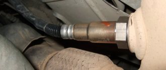
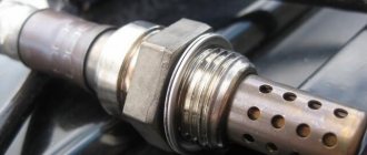
Once upon a time, an oxygen sensor was just a sensitive element, without any heater. The sensor was heated by exhaust gases and took a very long time. Strict toxicity standards required the sensor to quickly enter full operation, as a result of which the lambda probe acquired a built-in heater. Therefore, the VAZ oxygen sensor has 4 outputs: two of them are a heater, one is ground, and one is a signal.
Of all these outputs, we are only interested in the signal one.
The voltage waveform on it can be seen in two ways:
- scanner
- motor tester, connecting the probes and starting the recorder
The second option is preferable. Why? Because the motor tester makes it possible to evaluate not only the current and peak values, but also the shape of the signal and the rate of its change. The rate of change is precisely a characteristic of the health of the sensor.
So, the main thing: the oxygen sensor reacts to oxygen . Not on the composition of the mixture. Not at the ignition timing. Not for anything else. Only for oxygen. This must be realized.
The physical principle of operation of the sensor is described in many books devoted to electronic engine control systems, and we will not dwell on it.
A reference voltage of 0.45 V is supplied to the signal pin of the sensor from the ECU. To be completely sure, you can disconnect the sensor connector and check this voltage with a multimeter or scanner. Everything is fine? Then we connect the sensor back.
By the way, on old foreign cars the reference voltage “floats away”, and as a result, the normal operation of the probe and the entire system is disrupted. Most often, the reference voltage when the sensor is disconnected is higher than the required 0.45 V. The problem is solved by selecting and installing a resistor that pulls the voltage to ground, thereby returning the reference voltage to the required level.
Further, the sensor operation scheme is simple. If there is a lot of oxygen in the gases surrounding the sensor, then the voltage on it will drop below the reference 0.45 V, to approximately 0.1V. If there is little oxygen, the voltage will become higher, about 0.8-0.9 V. The beauty of the zirconium sensor is that it “jumps” from low to high voltage when the oxygen content in the exhaust gases corresponds to the stoichiometric mixture. This remarkable property is used to maintain the composition of the mixture at the stoichiometric level.