8 basic DIY regulator circuits. Top 6 brands of regulators from China. 2 schemes. 4 Most asked questions about voltage regulators.+ TEST for self-test
A voltage regulator is a specialized electrical device designed to smoothly change or adjust the voltage supplying an electrical device.
Voltage regulator
Important to remember! Devices of this type are designed to change and adjust the supply voltage, not the current. The current is regulated by the payload!
TEST:
4 questions on the topic of voltage regulators
- Why do you need a regulator:
a) Change in voltage at the output of the device.
b) Breaking the electric current circuit
- What does the regulator power depend on:
a) From the input current source and from the actuator
b) From the size of the consumer
- The main parts of the device, which you can assemble yourself:
a) Zener diode and diode
b) Triac and thyristor
- What are 0-5 volt regulators for?
a) Supply the microcircuit with a stabilized voltage
b) Limit the current consumption of electric lamps
Answers.
a, a, b, a.
How to avoid 3 common mistakes when working with a triac.
- The letter after the triac code indicates its maximum operating voltage: A – 100V, B – 200V, C – 300V, D – 400V. Therefore, you should not take a device with the letters A and B to adjust 0-220 volts - such a triac will fail.
- A triac, like any other semiconductor device, gets very hot during operation; you should consider installing a radiator or an active cooling system.
- When using a triac in load circuits with high current consumption, it is necessary to clearly select the device for the stated purpose. For example, a chandelier with 5 bulbs of 100 watts each will consume a total current of 2 amperes. When choosing from the catalog, you need to look at the maximum operating current of the device. Thus, the MAS97A6 triac is designed for only 0.4 amperes and will not withstand such a load, while the MAS228A8 is capable of passing up to 8 A and is suitable for this load.
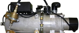
Why do you need a shunt voltage regulator?
Standard outboard generator voltage regulators are automotive-style regulators that work well under the following conditions:
In cars, when starting the engine, the battery is discharged by 5-10%, after which, even at idle, the generator power is sufficient to power all consumers and recharge the battery. Since the starter battery is not significantly discharged, charging it does not take much time and the second charging stage required for traction batteries becomes unnecessary.
Outboard motor voltage regulators are chargers with maximum current limitation and a voltage of 13.8 - 14.2 volts. But the voltage of 13.8 volts is higher than the recommended voltage of the maintenance charging stage for deep-discharge batteries, and the voltage of 14.2 is lower than the voltage of the saturation stage.
A generator with a standard regulator will never fully charge a deep-discharge battery, but will only overcharge it and damage it if it is connected to the battery for a long time.
RN on 2 transistors
This type is used in circuits of particularly powerful regulators. In this case, the current to the load is also transmitted through a triac, but the key terminal is controlled through a cascade of transistors. This is implemented like this: a variable resistor regulates the current that goes to the base of the first low-power transistor, which, through the collector-emitter junction, controls the base of the second high-power transistor and it opens and closes the triac. This implements the principle of very smooth control of huge load currents.
SNiP 3.05.06-85
Answers to the 4 most frequently asked questions regarding regulators:
- What is the permissible deviation of the output voltage? For factory instruments of large companies, the deviation will not exceed + -5%
- What does the regulator power depend on? The output power directly depends on the power source and on the triac that switches the circuit.
- What are 0-5 volt regulators for? These devices are most often used to power microcircuits and various circuit boards.
- Why do you need a 0-220 volt household regulator? They are used for smooth switching on and off of household electrical appliances.
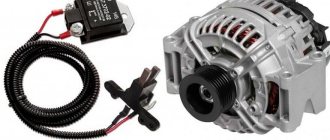
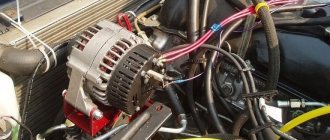
Additional regulator for car generator
Charging the battery in a car from a standard generator, especially in the winter, can cause some difficulties. Due to the operating error of the built-in voltage regulator, the current supplied to the excitation winding of the generator is insufficient to maintain the output voltage at 14.2...14.7 V, even without connecting consumers. Connecting a load, namely low beam lamps and various types of heaters, only aggravates the situation. Constant undercharging threatens the formation of lead sulfate on the battery plates, which reduces its capacity and, ultimately, not only prevents the engine from starting, but also damages the battery. For example, in its instructions it states: “For efficient and complete charging of batteries manufactured using Ca/Ca technology, the charger must provide a charging voltage of 16.0 V.” For an on-board network, this voltage is too high, but for charging in winter during trips, 14.5...14.8V is enough. A very popular solution to this problem on the Internet is to connect a diode in series to the power supply gap of the car generator voltage regulator. The essence of the improvement is as follows. The built-in generator regulator monitors the vehicle's electrical supply voltage. Adding a diode subtracts 0.5...0.7V from its supply voltage, depending on its type and load current. The regulator will strive to compensate for this voltage drop, since the supply voltage in the network has decreased, the current in the excitation winding of the generator will be increased to a value that will add exactly this value of the voltage drop, which will lead to an increase in the voltage of the on-board network. The method is simple and effective. But there is a drawback - due to the specific type of diode, load current and ambient temperature, the voltage drop may differ significantly from the required one. The proposed design will help to introduce predictability into the operation of a car generator by adding an adjustable voltage boost - connecting the proposed device between the power supply of the standard built-in car generator and the power supply of the car's on-board network.
The scheme is quite simple:
The basis of the circuit is op-amp DA2. It compares the reference voltage coming from elements C1, R1...R3, DA1 with the voltage taken from the drain of transistor VT1. A decrease in the drain-source voltage drop of VT1 relative to the reference voltage leads to its closing, which stabilizes the subtractive voltage of the generator regulator at the level set by resistor R3. Elements R4, R5, C2 prevent self-excitation of the circuit; op-amp DA2 without them on the capacitive load, which is the gate VT1, will not work normally. Capacitors C1, C3…C5 filter noise in the power supply circuit. Diode bridge VD1 - emergency. In case of abnormal operation of the regulator, it will not allow the voltage drop in the supply circuit of the voltage regulator to exceed 1.4V. Resistor R6 is necessary for the initial adjustment of the voltage drop between the drain-source terminals of transistor VT1 without connecting to the generator.
Photo of the assembled device:
Elements C1, C4, C5, DA1, R3 are glued to the board. This will help them survive vibration while the car is moving. The soldering side of the PCB components is coated with acrylic varnish to protect it from moisture:
The board itself is installed on the radiator:
Actually, a more modest radiator would suffice, an aluminum plate 5mm thick would suffice, but whoever has what is available. The external components are also partially coated with acrylic varnish. The entire assembly is housed in a suitably sized housing:
It also has a regulator switch for operation in the warm season:
In this case, it closes the input and output circuits (drain - source of transistor VT1), eliminating the influence of the device on the operation of the generator.
The regulator, assembled from serviceable elements, does not require additional settings. Adding the required voltage to the vehicle's electrical system is carried out by adjusting resistor R3. This value is monitored using a voltmeter between the input and output circuits of the regulator (drain - source of transistor VT1).
About replacing elements. Any op-amp DA2 is suitable, allowing operation at input voltages equal to the supply voltage; the datasheet indicates “common-Mode Input Voltage Range Includes VCC+”. Of the least exotic ones, LF355/6/7 op-amps are suitable. Here it is necessary to add that the use of a collet socket for an op-amp is a necessary measure. What was sold under the label TL071CN did not correspond to reality - they did not operate from input voltages equal to the supply voltage. I had to pick it up. If there are no problems with the original op-amps, it is better to solder the chip directly to the board. Transistor VT1 can be replaced with IRF5210N or similar. However, we should not forget that the drain-source resistance of the transistor used limits the minimum voltage drop across the regulator, and therefore the minimum voltage increase in the on-board network. In other words, transistors with a high drain-source resistance will work like regular resistances even when an opening voltage of 15V is applied to the gate-source. Any diode bridge VD1 is suitable for convenient installation on a radiator with a “screw”. In general, this is precisely the reason for choosing the diode bridge.
It would be possible to use 2 diodes connected in series, but they are more difficult to attach to the radiator. It is also worth noting that if the voltage boost does not exceed 0.6V, you can limit yourself to only one protective diode. In the case of using a diode bridge, you can connect the “~ ~” pins with “+” or “-” on the board with a jumper. The task of DA1 is to maintain a stable reference voltage regardless of the ambient temperature. The reference voltage source DA1 can be replaced with a low-voltage zener diode or stabistor. In this case, you may have to change the values of resistances R2, R3 for smooth adjustment. As a last resort, instead of DA1, you can use 3 series-connected 1N4148 diodes - this will work, but the error will be +-6.3 mV per change of one degree Celsius. If you adjust the voltage drop of the regulator “in cold weather” (with resistor R3), this may turn out to be acceptable due to relatively small temperature fluctuations.
To simplify installation in the car hood, it makes sense to provide connection terminals:
And the most important thing. For this modification of the generator, it is necessary that the built-in regulator of the automobile (or tractor) generator has a separate power supply. For example, from the ignition switch. In this case, the connection will not cause any difficulties. In contrast to design solutions, where the built-in regulator is powered from the internal circuits of the generator. In this case, you cannot do without partial disassembly of the case...
List of radioelements
| Designation | Type | Denomination | Quantity | Note | Shop | My notepad |
| C1 | Electrolytic capacitor | 10 µF | 1 | Search in the Otron store | To notepad | |
| C2, C3 | Capacitor | 1 µF | 2 | Search in the Otron store | To notepad | |
| C4, C5 | Electrolytic capacitor | 220 µFx25V | 2 | Search in the Otron store | To notepad | |
| DA1 | Voltage reference IC | LM385-2.5-N | 1 | Search in the Otron store | To notepad | |
| DA2 | Operational amplifier | TL071 | 1 | Search in the Otron store | To notepad | |
| R1 | Resistor | 1.8 kOhm | 1 | Search in the Otron store | To notepad | |
| R2 | Resistor | 13 kOhm | 1 | Search in the Otron store | To notepad | |
| R3 | Trimmer resistor | 20 kOhm | 1 | Search in the Otron store | To notepad | |
| R4 | Resistor | 20 kOhm | 1 | Search in the Otron store | To notepad | |
| R5 | Resistor | 100 Ohm | 1 | Search in the Otron store | To notepad | |
| R6 | Resistor | 1.5 kOhm 0.5 W | 1 | Search in the Otron store | To notepad | |
| VD1 | Diode bridge | GBU10005 | 1 | Search in the Otron store | To notepad | |
| VT1 | MOSFET transistor | IRF4905 | 1 | Search in the Otron store | To notepad | |
| Add all | ||||||
Attached files:
- Polzovatelyam.zip (73 Kb)
Remote controller
This often happens to drivers. The brushes of the generating device burn out. The regulator is built in along with the brushes. We have to change everything together. And here’s some advice from experts: it’s better to install an external regulator than a built-in one. The models released recently have not been praised very much.
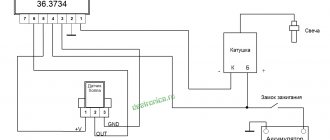
Okay, do you think I’ll install an external one, but how do I connect it? It turns out that there is a convenient scheme that makes it easy to carry out all this modernization.
Some important points:
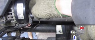
- do not confuse the chips on the regulator numbered 67 and 15 (the first should be connected to the generating device, and the second should go to the fuses);
This is what the connection diagram looks like
In the lower photo we see a diagram that shows the connection of the already built-in regulator relay.
It is suitable for connecting to “fives”, “sevens”, VAZ 2104, if the PG is installed from a VAZ “kopek”. As you can see, the remote-type regulator relay is connected via two terminals. Pin 15 goes to the fuse.
The second pin 67 is connected to the generator. The wire is connected to the brush chip.
Also, the remote-type relay must be connected to ground - any part of the body.
A relay is nothing more than a switch that serves to close and disconnect individual zones of an electrical circuit that occur at specific electrical values. A machine relay is otherwise called a load voltage switch, and this is 100 percent true. When the power supply unit, fan or starter consumes more current than necessary, the relay trips.
The relay consists of an electric type magnet, an armature and a switch. In this case, the electromagnet is a cable twisted around an inductor with a magnetic rod, and the armature is a special plate that controls the contacts.
As soon as electrical voltage passes through the magnet winding, an electric field is created. A special pusher presses the armature against the core and, thereby, the contacts switch.
Attention. There are two types of relays used on VAZ cars. This is a non-contact relay-regulator and MER (electric). It is the diagram of the last relay that is shown in the picture below.
The non-contact relay or NERR is a fairly new unit that does not require any additional adjustments or regulation. As for the MED, this is an old-style device, the production of which has currently been suspended.
So, the BRN or built-in regulator is a device consisting of a microcircuit, a transistor and a housing with brushes. If the built-in regulator fails, it is replaced with a new one, or an external one is installed.
The external regulator is easy to install if you strictly follow the instructions.
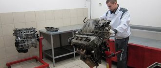
Modernization involves dismantling and disassembling the generating device.
Scheme number 1
There was a stabilized switching power supply that gave an output voltage of 17 volts and a current of 500 milliamps. A periodic change in voltage was required in the range of 11 - 13 volts. And the well-known voltage regulator circuit on one transistor coped with this perfectly. I added only an indication LED and a limiting resistor to it. By the way, the LED here is not only a “firefly” signaling the presence of output voltage. With the correct value of the limiting resistor, even a small change in the output voltage is reflected in the brightness of the LED, which provides additional information about its increase or decrease. The output voltage could be changed from 1.3 to 16 volts.
KT829, a powerful low-frequency silicon compound transistor, was installed on a powerful metal radiator and it seemed that, if necessary, it could easily withstand a heavy load, but a short circuit occurred in the consumer circuit and it burned out. The transistor has a high gain and is used in low-frequency amplifiers - you can really see its place there and not in voltage regulators.
On the left are removed electronic components, on the right are prepared for replacement. The difference in quantity is two items, but in terms of the quality of the circuits, the former and the one that was decided to be collected, it is incomparable. This begs the question: “Is it worth assembling a scheme with limited capabilities when there is a more advanced option “for the same money”, in the literal and figurative sense of this saying?”