How a glass closer works: principle of operation
When the automatic closer is activated, the windows usually close sequentially.
The closer must understand that the glass is closed (analyzes, for example, noise or flowing current from the electric motor) and must also understand the absence of load and the limitation of operating time (the so-called cable break mode). There are door closers that can also open windows and detect obstacles (like the native door closer in Camry), there are door closers with memory, etc., it all depends on the embedded algorithm in the brain of the door closer. Closer units are available to control two or four panes.
In order to install the closer yourself, you need hands that can hold a soldering iron, you need to know how to use the control and/or what the numbers on the tester screen mean, what “plus” and “mass” are, accuracy, desire and time.
An example of a door closer
Let's consider an ordinary door closer that can only raise windows (two or four - it doesn't matter). That is, they gave a signal to close - the first window went up, then the second, then the third, etc.
First you need to understand the principle of controlling the opening and closing of windows using standard control buttons:
The raising and lowering of the window is controlled by a DC motor, the rotation of which depends on the polarity of the voltage. In the normal position, when the control buttons are not pressed, the motor is connected at both ends to ground, so it is motionless.
If you press the “Close” button, then the plus will fall on one contact of the motor (there is ground on the second contact of the motor), and accordingly the motor will begin to spin (well, let’s say clockwise).
If you press the “Open” button, then the plus will go to another contact of the motor, the rotation will be in the other direction, and accordingly the window will begin to move down. Well, if you press both buttons at the same time, then +12 Volts will appear on both motor contacts, there will be no voltage difference and the motor will remain motionless.
All other windows are controlled in the same way. The circuit is powered through a fuse, through contact IG2 of the ignition switch (second position of the key in the lock).
Installing and connecting power windows: how to connect power windows correctly
In general terms, having selected the mechanism, you first need to remove the door card, after which you will need to disconnect the battery terminals. Afterwards, the old electric window regulator (if equipped) is removed, and the wiring from it is first disconnected. If the device is mechanical (manual window lift), dismantling is also required.
We recommend: Blue smoke from exhaust
By the way, before removing the window lifting mechanism, the glass itself must be secured with wide stationery tape in the most convenient position for installing the window lifting mechanism. Then you can install the new mechanism, and then proceed to connect it.
Please note that if exactly the same analogue is used to replace an existing window regulator, then the wiring is simply connected in the same way as the connection was made previously.
If another window regulator is installed or it was not there initially, the connection diagram of the window regulators, the pinout of the window regulator, etc. must be studied in advance.
It is also necessary that the window lift buttons be prepared in advance in case they are missing or existing ones are faulty. Let's take a closer look at the procedure using the example of replacing a standard manual mechanism with an electric analogue.
Installing a window regulator
Let's look at installing a window regulator using the example of a VAZ 2109. Before starting work, you should prepare:
- a cross and a flat screwdriver;
- nippers and pliers;
- a set of keys;
- knife and broaches;
- electrical tape, copper wire, wide tape, zip ties, etc.
You will also need pistons for attaching the door card and other elements that may require replacement after removing the door cards. These features should be taken into account and all necessary parts should be purchased in advance.
Do-it-yourself door closer installation
The installation diagram of the block is quite simple. The more doors and additional functions, the longer installation time will be required. The mechanism is installed anywhere inside the car. More often the device is mounted under:
- door trim;
- front panel of the car.
The only condition that must be observed when installing the unit is protection from moisture.
What you need
The kit includes a connection diagram. During installation, you must strictly follow the recommendations, especially if you install the device yourself. Additional tools you will need:
- flat screwdriver;
- crosshead screwdriver;
- pliers;
- electrical tape, double-sided tape;
- side cutters.
In rare cases, heat shrinking may be necessary. Replace the heat shrink tube with insulating tape or use it together.
Step-by-step instruction
When installing the sensor on a car yourself, it is difficult to avoid mistakes. This applies to people who do not have mechanical skills. We recommend following the step-by-step instructions:
- Turn on the car's ignition. Check whether the power window control unit is working properly. If you notice any malfunctions, replace the relay with a special jumper.
- Remove the car door trim from the driver's seat.
- Install the device onto the frame.
- Connect the car wiring, main unit. This is an important part of the installation. Connect the red wire of the sensor to the white one. The latter leads to any door button. This will connect the closer to the current supply system.
- After connecting the unit, you need to connect the black wire to ground or connect the cable to the wire leading to it.
- Connect the yellow or white wire to the central car lock.
- Take the wire that regulates the rise of the car windows and cut it in half. Connect 4 cables.
- Now you need to cut the orange wire. Connect the cable to the closer keys.
- Repeat the procedure for blue and green cables.
- Check the integrity of the wire connections.
- Solder the cables.
- Isolate the circuit.
- Assemble the door trim, check the operation of the car alarm.
The scheme is suitable for most car models, frame and frameless glass. Be sure to read the instructions before installation. The manual is included with the device and is written in two languages.
Pandora DX-90
- Description
- Characteristics
- Questions and answers (0)
- Reviews (0)
- Files and instructions
- Our works
- Control method: Key fob with LCD display
- Autostart - Yes
- GSM - No
- GPS and GLONASS - No
- CAN interface - Yes
- Key fob with LCD display - Yes (key fob with LCD D-010 for DX-90, DX-90 B, DX-90 BT, DX-9x, DX-6x)
All characteristics
This model was discontinued due to the release of the new Pandora DX-90BT system
Pandora DX-90 car alarm is equipped with a full set of digital interfaces: an integrated 2CAN controller for working with modern cars and a switchable LIN interface for monitoring and controlling pre-heaters, as well as bypassing standard immobilizers.
The Pandora DX-90 comes with the new D-010 key fob, the fruit of the design team's hard work - it's the first Pandora key fob to feature a graphical OLED display. The keychain is distinguished not only by its stylish appearance, but also by its ergonomics, as well as its high range. The key fob uses a multi-channel 868 MHz radio path and a non-scannable dialogue code. Despite its modest overall dimensions, the D-010 keychain is powered by the usual AAA battery.
Pandora DX-90 alarm system has an autostart function - the owner can start the engine remotely and configure automatic start from the key fob at any time. Like other modern Pandora alarm systems, this model is able to “bypass” the standard immobilizers of many cars without using a standard key, which significantly saves the owner’s money.
Pandora DX-90 is equipped with shock, motion and tilt sensors, the triggering of which, as well as the triggering of an alarm in any other protected zone, the owner immediately receives a notification on the key fob.
Equipment:
- Base unit
- Main remote control with LCD display
- Plastic card with an individual secret code
- Optional remote control key fob (without LCD display)
- Main cable
- Cable with three-color LED status indicator
- Cable with VALET button
- LIN interface wire
- Mounting kit
- Operation and installation manual
- Relay trigger module
- Engine temperature sensor
- Package
Technical characteristics and parameters of Pandora DX-90
- Control method: Key fob with LCD display
- Autostart - Yes
- GSM - No
- GPS and GLONASS - No
- CAN interface - Yes
- Key fob with LCD display - Yes (key fob with LCD D-010 for DX-90, DX-90 B, DX-90 BT, DX-9x, DX-6x)
- Additional key fob without LCD display - Yes (key fob R387 for Pandora DX and Pandect X series)
- Control via website and apps for Android and iOS - No
- Turbo timer - Yes
- Pre-heater control - Yes
- SLAVE mode - Yes
- Control of the key fob-car communication channel - Yes
- Shock/tilt/motion sensor - Yes
- Digital blocking relay - Option BM-105
- Dialogue code - Yes
- mini or micro-USB port - Yes
- Relay trigger module - rmd5
- Pandora CLONE support - Yes
Programs and instructions for Pandora DX-90
- Firmware (file pld), version 2.28 dated 06/28/2017.x-empty Operating instructions.pdf Connection diagram.pdf Connection diagram for bypassing the standard immobilizer for Pandora DX 90, version dated 10/14/2016.pdf Table of statuses and commands dated 06/28/2017 .pdf Comparison table of Pandora systems.pdf Changes in firmware from 06/29/2017.plain Pandora Alarm Studio Pandora DXL Loader
Questions and answers about Pandora DX-90
In this section we help you choose an alarm system for your car. Technical advice is not provided in this section. For advice on technical issues, contact technical support toll-free at 8-800-700-17-18.
Frequently asked questions and useful articles:
- Pandora DX-90 goes on sale
- What will happen to the warranty on my car?
- Why disassemble the standard key to connect autostart?
- Will there be keyless bypass using Pandora, Pandora CLONE?
- How much money does it cost per month for GSM communication with alarm?
- What is the difference between the different Pandora security systems?
Implementation scheme
There are a lot of circuits and implementations of door closers and designs on the market, but they all work on the same principle - duplicating the standard “Close” button with its own internal relay, which is turned on and off by the brains of the door closer.
Closers are produced as universal ones, for controlling “ground” or “plus”. In Toyotas, window control is a plus.
Accordingly, according to the desired option in the closer circuit, you need to connect the power wires or switch the jumper in the closer; this item is described in detail in the installation instructions.
Connecting the power window closer to the alarm system. We do everything right
Car window closers are gaining more and more popularity every day. For normal operation of the device, the power window closer is connected to the alarm system so that when setting the car to the alarm, do not leave the windows open. Most modern cars are produced with door closers already installed; such a device is a small automated mechanism that closes the windows when the security mode is set.
Closing the windows when arming.
And I don’t know what happened to me to get into the alarm system, but the question arose, like all alarm systems on mine, without exception, there is a wire for locking the windows when arming...
So the question is, is it really possible to implement this in the 10th example...? Is there a power window module...?
Do not offer anything additional, such as glass closers.
I admit that I haven’t taken the doors apart yet... hence the question...
Buy a polybasic module so that all 4 windows go up, attach the wire of the additional signaling channel to it, the instructions say which wire and the diagram is given.
Contents of delivery
The starline GSM module is delivered in a small cardboard box, which contains two books with a description and installation instructions, a warranty card, a SIM card, a Telematics system flyer, and a reminder card. The connection diagram, which may be required for self-installation, has a high degree of detail, is made in color and is designed for an inexperienced car enthusiast.
The hardware is located at the bottom of the package behind a folding cardboard partition and includes the GSM module itself, an LED indicator and a set of wires that are necessary to complete the connection.
Principle of operation
The car is equipped with motors that raise and lower the glass. This process is carried out by applying voltage to the motor contacts. If a closer is installed, this connection is interrupted.
It is in this gap that it is necessary to install an additional block, and when you press the button further, the signal first goes to the control unit, and then is sent to the lift motor. If the car is set to an alarm system, a signal is sent to this unit about the need to automatically close all windows.
As a result, we can say that factory car window closers can be installed by almost every driver with at least a little knowledge of electrics, especially since the instructions are included.
But not everyone can solder and install a homemade device, and the reliability of such a device is highly questionable.
Although there are already good models that have been working for years. But here you need to focus on the reviews of people who use such devices and the qualifications of the master who made them.
Today, more and more motorists are paying attention to the comfortable operation of vehicles. On sale you can find many different accessories designed to increase comfort when using a car. One such device is a window closer, which can be installed on 2 or 4 windows.
Principle of operation
The car is equipped with motors that raise and lower the glass. This process is carried out by applying voltage to the motor contacts. If a closer is installed, this connection is interrupted
It is in this gap that it is necessary to install an additional block, and when you press the button further, the signal first goes to the control unit, and then is sent to the lift motor. If the car is set to an alarm system, a signal is sent to this unit about the need to automatically close all windows.
Types and features of door closers
First, you need to decide on the operating algorithm of glass closers, their types and features. This information will help you make your choice in the future. So, let's start with a description of how this device works.
The door closer is an electronic control unit that is installed between the electric drive (electric motor) of the windows and its control button on the car doors. When the alarm is disabled, it does not work, passing command signals through itself to lower or raise the windows. And when the alarm and central locking are turned on, it automatically checks the condition of the windows, and if they are open, the control unit sends a command to the electric drive to close them.
Automatic door closer with connection to signaling
Nowadays, you rarely see a car without electric windows; they often have automatic closers only on the driver's window. Automatic closers allow you to raise or lower the window with one click without holding the button. To fix the position of the window, a short press of the button is enough.
Old car models or budget options may not contain them at all. However, they are not at all difficult to make yourself; it does not require much effort. Next, two options for assembling and connecting door closers (with and without alarm) will be provided.
If you don’t have electric windows at all, the diagram will be quite fair; if you buy an additional motor for raising the glass, connecting it will not be a problem.
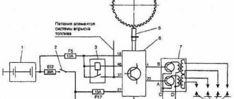
The diagram below shows a method for connecting power windows without a closer. According to the above diagram, pressing and holding the button raises the glass, while closing contacts 2 and 1, +12 V is supplied to the motor so that it moves in the direction of raising the glass.
Shorting pins 7 and 3 connects ground to the motor, completing the circuit. When you press and hold the button in the opposite direction, contacts 2 and 1 open, and 2 and 7 close, voltage of reverse polarity is applied to the engine and the engine runs in the other direction. The ground is accordingly closed on contacts 1 and 6.
The circuit with an automatic closer, but without connection to the alarm system, looks like this:
From the diagram it can be seen that the module is installed between the motor and the button, i.e. The signal from pressing the button is sent to the module, processed there and only then sent to the window lift motor. A short press of the button will cause the glass to open or close continuously, without the need to continuously press the button.
Simple car window closer
Why I love the Russian automobile industry is because our cars have huge scope for creativity! I recently purchased a VAZ 2114 and it started...
Today I want to tell you about a glass closer. Of course, you could go and buy a ready-made module for 400 rubles, or even cheaper... but that’s not about us! In addition, I wanted to implement automatic full opening and full closing using a standard window lifter button. The operating algorithm is as follows: if we want to completely open (close) the window, briefly press the open (close) button. If you need to set the glass to the middle position, hold the button, the glass moves, release it and it stops. Well, of course, we connect the whole thing to the signaling system. We put it on guard and rejoice.
Figure 1 shows a diagram of the standard connection of power windows for the front doors of a VAZ 2114.
Picture 1.
When the window open button is pressed, contacts 2 and 7 close and supply +12V to the window lift motor. In this case, contacts 1 and 6 of the button remain closed and connect the window lift motor to the vehicle ground. The glass opens. When the window close button is pressed, contacts 1 and 2 close and supply +12V to the window lift motor. In this case, contacts 3 and 7 of the button remain closed and connect the window lift motor to the vehicle ground. The glass closes.
Figure 2 shows a diagram for connecting door closer modules without connecting to an anti-theft alarm system. Each door has its own module.
Figure 2.
Now, when you press the window open button, +12V is supplied to the closer module and, depending on the length of time you hold the button, the closer module supplies +12V to the window motor for the duration of pressing and holding the button or until the window is fully opened. If you need to fully open the window, you must briefly press (+12V pulse duration at the module input up to 0.2 seconds) the opening button. When you press and hold the button, the window lift operates almost as usual - the window opens while the button is pressed. “Almost” because the glass movement begins with a delay of 0.2 seconds after pressing the button. The same is true when closing a window. When the glass is moving in full open or close mode, briefly pressing the button in the opposite direction will stop the movement. When the extreme positions are reached, glass movement is only possible in the opposite direction.
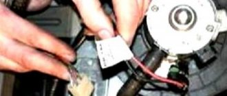
Let's connect
In order for the window closer that was just installed on the driver's door to work properly, you will need to make two different connections. The first is to the 12V battery, the second is from the alarm signal wire to ground.
The red wire will connect to 12 V, the black wire must be connected to ground. The yellow will go to the central lock and then connect to the white. The conductor that is responsible for the process of raising the glass must be attached to the other conductors directly into the gap. To do this, you need to cut the conductor and connect it from the side of the button and the motor.
Next, the diagram for connecting the glass closer involves cutting the orange wire. It connects to the closer on the button side. Now let's cut the blue wire, and it should connect to the wires from the closer on the side where the buttons are located.
To put it simply, the black and white wires are connected to ground and positive. The rest are input for buttons and output for motors. When connecting, you need to find a wire in the door through which the impulse will pass when the car is removed from one level of protection mode and when another is installed.