Electrical wiring in a car plays an important role, connecting all electrical lines, electrical equipment and electronics. Therefore, when purchasing a new car, a service book with electrical diagrams is included. If there is a malfunction of any element in the on-board network, the driver will be helped by a diagram of the location of electrical equipment with wiring. The overview of the diagrams is designed to help beginners, as well as car enthusiasts who bought a used Lada Granta car without a diagram. In the event of a minor malfunction of any unit, an experienced driver can handle it himself, having a multimeter with him. The most important thing is to follow safety precautions when working with electrical equipment.
Electrical diagram. general description
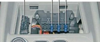
The electrical diagram of Lada Granta cars in Norma and Standard configurations is the same, and this review provides a description of these drawings. All energy consumers in the graphic image are indicated by conventional symbols (pictogram) and an ordinal (ordinal) number. All pictograms are connected by colored lines into a common switching network. The machine has two mounting blocks of safety elements. The first is behind the battery in the engine compartment with 5 fuses. The second cabin unit is located on the left at the bottom of the console, it contains 32 fuses and 12 relays.
Relay function and applicability
K1 - fan of the internal combustion engine cooling system; K2 - central locking; K3 - additional starter relay; K4 - spare relay; K5 — turn indicator and emergency flasher switch; K6 - wiper relay; K7 - high beam headlights; K8 - horn relay; K9 - low beam headlights; K10 — heated rear windshield; K11 - main relay; K12 - fuel pump relay.
The pinout or pinout contains a large number of harnesses that are connected using car system connectors. The presented general diagram is divided into several blocks for ease of perception:
- front end;
- ignition system;
- dashboard:
- rear end.
All harnesses are connected to each other by connectors, each bundle of wires has its own serial number. The cable in the diagram is marked, where the first number indicates which element it goes to, the second indicates the contact. In the graphic diagram, each element is assigned a number with subsequent interpretation.
Functional purpose and characteristics of the shield
The tachometer displays the speed of the crankshaft of the power plant.
The “Check Engine” indicator lights up when you turn the ignition key, and after the engine starts, it goes out. If it lights up while driving, it indicates a failure of some element of the power unit control system; you should turn off the engine, go to the station and fix the problem. The turn indicator flashes in the appropriate direction. The ABS indicator also goes out after starting the engine; constant lighting indicates a system malfunction. The immobilizer alarm determines the vehicle's security mode. The oil indicator is constantly illuminated if the lubricating oil level in the system is insufficient. The coolant overheat indicator turns red when it is overheating, and an audible alarm indicates that the engine is overheating above 115° and will sound until the temperature drops to the maximum limit. The low brake fluid level indicator lights up red and indicates problems with the brakes (it is strictly prohibited to continue driving).
The battery charge indicator while driving indicates a lack of charging current (problems with the generator or power wires). To troubleshoot problems with the electrical part of the car, the Grant panel pinout may be useful. The speedometer displays the current speed of movement. The exchange rate stability indicator (ESC) is constantly lit when the system is turned off, and the lighting and flashing mode informs about the operation of the system; when the signal is constant, the system does not work.
The indicators for turning on the high and low beam headlights inform you that the corresponding lighting mode is turned on. The fog lamp indicator informs about their operation. The daily counter reset button resets the daily mileage readings in the LCD display.
Ignition system wiring harness pinout diagram
1 — oil pressure indicator; 2 — generator unit connector; 3 — throttle valve power supply; 4 — antifreeze temperature sensor; 5 — block of ignition system wire bundles to the block of instrument panel harnesses; 6 — power supply to the adsorber purge valve; 7 — speed sensor (speedometer); 8 — mass air flow sensor; 9 — DPKV; 10 — oxygen saturation sensor; 11 — control controller; 12 — oxygen saturation diagnostic sensor; 13 — ignition coil; 14 — spark plugs; 15 — nozzle control; 16 — blocks of ignition harnesses and injector wire bundles; 17 — detonation control sensor.
Electrical circuits
Front wiring harness wiring diagram
- right headlight;
- electric washer motor;
- left headlight;
- starter;
- rechargeable battery;
- main fuse box;
- generator;
- sound signal;
- front wiring harness blocks to instrument panel wiring harness blocks;
- front wiring harness blocks to instrument panel wiring harness blocks;
- front wiring harness blocks to instrument panel wiring harness blocks;
- reverse lamp switch;
- electric fan of the engine cooling system.
Electrical connection diagram of the air supply box wiring harness
- windshield wiper motor;
- brake fluid level sensor;
- air supply box wiring harness block to the instrument panel wiring harness block.
Electrical connection diagram for the ignition system wiring harness
- oil pressure warning light sensor;
- generator;
- throttle body with electric drive;
- coolant temperature sensor;
- ignition system wiring harness block to the instrument panel wiring harness block;
- adsorber purge solenoid valve;
- speed sensor;
- mass air flow sensor;
- crankshaft position sensor;
- oxygen concentration sensor;
- controller;
- diagnostic oxygen concentration sensor;
- ignition coils;
- spark plug;
- nozzles;
- ignition system wiring harness and injector wiring harness connectors;
- knock sensor.
Instrument panel wiring harness wiring diagram
- the instrument panel wiring harness blocks to the front wiring harness blocks;
- the instrument panel wiring harness blocks to the front wiring harness blocks;
- the instrument panel wiring harness blocks to the rear wiring harness blocks;
- the instrument panel wiring harness blocks to the rear wiring harness blocks;
- lighting control module;
- ignition switch;
- on-board computer mode switch;
- wiper switch;
- instrument cluster;
- light switch;
- trunk lock actuator switch;
- diagnostic block;
- instrument panel wiring harness block to the air supply box wiring harness block;
- rear window heating switch;
- hazard switch;
- brake light switch;
- connectors for the instrument panel wiring harness to the radio;
- connectors for the instrument panel wiring harness to the radio;
- rotating device;
- driver airbag module;
- –
- mounting block:
- electric power steering;
- cigarette lighter;
- heater control panel backlight;
- illuminator;
- instrument panel wiring harness block to the ignition system wiring harness block;
- controller;
- clutch pedal position signal switch;
- electronic accelerator pedal;
- additional resistor;
- heater electric motor;
- heater motor switch;
- door lock system control unit.
K1 – relay for the electric fan of the engine cooling system;
K2 – door lock relay;
K3 – additional starter relay;
K4 – additional relay;
K5 – relay-interrupter for direction indicators and hazard warning lights;
List of elements on the Lada Granta dashboard wiring harness diagram
As with all cars, this is the most complex block in the overall electrical connection diagram, due to the large number of connectors.
1/2 — blocks of the tidy harness to the front wire bundle; 3/4 — bundles of instrument panel wires to the rear harness; 5 — lighting control unit; 6 — ignition switch; 7 — computer mode toggle switch; 8 — windshield wiper mode switch; 9 — instrument board; 10 — light signaling switch; 11 — luggage compartment lock switch; 12 — diagnostic block; 13 block of the instrument wiring harness to the block of the air supply wire bundle; 14 — rear window heater breaker; 15 — alarm switch; 15 — brake light switch; 17 — connection of radio equipment speakers; 18 — connector for connecting a radio; 19 — steering wheel rotating device; 20 — driver airbag module; 21 - no; 22 — mounting fuse block; 23 — power steering connector; 24 — cigarette lighter socket; 25 — backlight lamp for stove control; 26 — interior lamp; 27 — block of the tidy harness to the block of the ignition wire bundle; 28 — control device; 29 — clutch pedal position signal breaker; 30 — electronic accelerator pedal; 31 — supernumerary resistor; 32 — stove motor; 33 — heater switch; 34 - door lock control module.
Detailed pinout diagram of the Lada Granta instrument panel pinouts
1 - to low oil pressure sensor; 2 - to the handbrake indicator switch; 3 — service diagnostics input; 4 - for external lighting switches; 5 - to the right turn signal toggle switch; 6 - similar to the left; 7 - CAN-L (high level); 8 - CFN-H (low level); 9 - to the signal for not fastening your seat belt; 10 - to the “RESET” button of the steering column lever; 11 — to the brake fluid level sensor; 12 - on the head optics - high beam; 13 - similar - low beam; 14 — to the rear fog lights; 15 - similarly, to the front; 16/18 — immobilizer antenna input; 17 — ground wire of the tidy; 19/21 - to the external terminal of the battery electrode No. 30/15; 20 — to the electric power steering drive; 22 - to the door sensor; 23/24 — “forward”, “back” button; 25 — for the outside air thermometer; 26 - to the float sensor.
Description of the Grants instrument board
All information from the sensors is displayed on the Lada Granta instrument panel in the most convenient and practical way for the driver to quickly familiarize himself with it, so as not to distract him from the road situation. The location of the indicators is thought out to the smallest detail; all necessary and important readings can be easily seen by looking below the top edge of the steering wheel. Secondary data is placed a little further away. The panel illumination does not distract the driver at night; all indicators are clearly visible at any time of the day. The panel includes:
- tachometer;
- engine control check indicator;
- left and right turn signal indicator;
- low oil level indicator;
- ABS warning light;
- immobilizer warning light;
- overheat indicator;
- brake system indicator;
- battery indicator;
- speedometer;
- ESC performance indicator;
- air cushion indicator;
- belt indicator;
- low fuel level sensor;
- flat tire indicator;
- electric amplifier indicator;
- Lada computer display;
- door open sensor;
- indicator for high or low beam headlights;
- front and rear fog lamp indicator;
- daily counter reset button.
Lada Granta: car rear pinout diagram
In the rear block of the car diagram, the equipment elements of the sides and rear are indicated. In addition, all additional equipment is connected through this part of the highways. The difficulty in pinouting the rear harness is that it is connected to 6 wire harnesses. Namely: 2 harnesses to the dashboard wiring harness; 4K wiring harness blocks for all doors.
1 — socket in connector 3 of the instrument panel; 2 - similar to connector 4; 3/4 — side turn indicators; 5 — parking brake position indicator; 6 — rear window heating element; 7 — interior lamp; 8 — driver’s seat belt on/off indicator; 9 — backlight lamp in the trunk; 10 — fuel pump power supply; 11/15 — rear right and left optics; 12 — luggage compartment lock drive; 13 — light switch in the cabin; 14 — supernumerary brake signal; 16-19 — connecting blocks of harnesses to the front and rear doors; 20 — airbag control module; 21 — clamp for state license plate lights.
Diagrams of individual elements of electrical equipment of the Lada Granta
In addition to the main blocks, the album contains graphic images of individual elements, for example: door wiring harnesses; lighting control.
Right front door pinout
1 — block of the door wire bundle to the rear harness block;
2 — window lift electric motor drive;
3 - locking device;
4 — switch device for lowering and raising glass;
5 — block of the door cable bundle to the front right speaker.;
Left front door pinout
1 - similar to the right door;
2 — electric motor of the left door glass lifting device;
3 - door lock;
4 — power window switch block;
5 — output to the speaker of the left door.
Lada Granta rear door pinout
The pin locations are the same on the left and right rear doors.
1 — connecting block of the rear door wiring harness to the tailgate wiring block; 2 - to the loudspeaker; 3 - to the locking device.
Electrical circuit of the lighting control module
| Contact | Purpose |
| 2 | Rear foglights |
| 4 | To the daytime running lights |
| 30 | +12 V (from generator pin 30) |
| 31 | Frame |
| 56 | To low beam headlights |
| 58 | To side lights and backlight lamps |
| Xz | + 12 V (from pin 15 of the ignition switch) |
Main characteristics of the electrical equipment of the Lada Granta car
Before you begin to study the electrical circuit, you need a clear understanding of the systems and all equipment of the car. It consists of the following:
- All systems are powered by a 12 volt battery, therefore no other voltages are permitted.
- To protect electrical networks in the car, blocks with safety elements and relays are installed. Often a car malfunction occurs due to a blown fuse. For example, if you cannot start the car, then this must be a faulty relay or a breakdown of the safety element of the fuel pump part.
- The main component of a car's electronic system is the engine control unit. Of course, if there are malfunctions in this system, the car’s engine will not start.
- All the most important electronic devices are connected via a terminal block and cable bundle to the instrument panel. If any icon remains on the dashboard after turning on the ignition and starting the engine, then there is a malfunction in the system.
- The engine control system (ECM) includes: controller (ECU); sensors monitoring engine parameters; executive modules. The ECU is located below the glove compartment, under the passenger's feet, namely under the floor covering. Its function includes: supplying voltage to sensors and actuators; control system diagnostics; troubleshooting and storing error codes.
Frequently encountered problems in the stable operation of electrical equipment:
- relay failure, fuse breakdown;
- corrosive deposits on connector contacts;
- fuse links burn out;
- failure of contacts in the terminal block.
A diagnostic device and a geographical image of the electrical connections of equipment and car systems will help to detect all damage.
Having an electrical circuit in the glove compartment, the driver will be able to fix a small malfunction on his own, this is especially true on a long journey. A knowledgeable driver, having studied the diagram of the required unit, represents the functional purpose of a particular circuit. However, we must remember that the electrical circuit of the Lada Granta equipment is quite complex for a person who is not related to technology. Therefore, in this case, if a malfunction is detected, you must contact specialists. In conclusion, a small reminder: electrical wiring cannot withstand large voltage drops in the on-board network. In other words, it is necessary to monitor the condition and state of charge of the battery.
Additional indicators on the panel
The LCD display on the panel displays information from the on-board computer. The open door indicator glows red if one of the doors is not closed. The low fuel indicator indicates the need to refuel (ignoring this signal may lead to failure of the fuel pump).
The weak tire indicator illuminates when tire pressure is low. If the driver is not wearing a seat belt, the seat belt sensor lights up. The airbag status indicator lights up in cases of system malfunction; you must contact a service station, since the airbag may inflate randomly. If any indicator fails, you can ring the system and find the reason; the pinout of the instrument panel will help with this.

