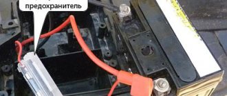
What is a switch and why is it needed?
To put it simply, a switch is a certain module (according to Feng Shui - a DC CDI or AC CDI module) in which electrical energy is accumulated, which at the right moment is supplied in the form of a pulse to the ignition coil, where it is multiplied many times and jumps out in the form of an electric spark between the spark plug electrodes.
Depending on the type of commutator, the energy necessary for the formation of spawn can be accumulated in the commutator in two ways:
- On switches of the AC CDI type - the energy required to form a spark on the spark plug is first formed in the high-voltage coil of the generator and then, in the form of alternating current, enters the switch, where it accumulates in the capacitor and at the right moment is supplied to the ignition coil in the form of a pulse
- On DC CDI type switches, the energy required to form a spark on the spark plug in the form of direct current comes directly from the battery, where it is converted into alternating current, multiplied by voltage and supplied to the capacitor
The switch power coils on the generator look something like this. Some generator models have two, some have only one.
To ensure that the spark passes at the right moment, a magnetic induction sensor (in collective farm parlance - “Hall sensor”) is included in the design of the generator and the switch like it. A magnetic induction sensor is essentially a regular alternating current generator, only in miniature.
On the outside of the generator rotor there is a small protrusion, when passing near the sensor - a small alternating pulse is formed in the sensor windings, which is sent to the switch thyristor - the thyristor opens and the energy accumulated in the capacitor is supplied to the ignition coil
Testing the switch
In order not to waste time, the test should begin by checking the electrical impulse that accumulates in the switch and at the right moment goes to the ignition coil.
We take a control light and connect one end of it to the green ground wire, the other to the black and yellow wire of the ignition coil. We turn the engine with the starter.
- If the light does not light, check the modules that ensure the operation of the switch
- If the light comes on, the switch and the modules that ensure its operation are working properly and the reason for the lack of a spark should be sought not in the switch, but, for example, in the ignition coil, ground or wires supplying current to it
If the switch and the modules that ensure its operation are in good working order, a 3W light bulb should glow at half-glow when the engine is cranked by the starter.
Malfunction
What prompted you to study the article on how to test the switch on a 4T scooter or any other common model? Most likely, your vehicle has stopped starting, but you don't know what exactly the problem might be. Perhaps the ignition is acting up, perhaps the engine is stalling. All this may or may not have a cause in the switch - this is the main problem of repair. You need to determine where exactly the problem is in order to fix it.
If your switch does not work or does not function well, then the low voltage pulse will not be transmitted to the ignition coil - accordingly, ignition will not occur. But the problem could be in the generator, the coil, or even the spark plug, so you need to know exactly how to check these elements. This material focuses specifically on the switch, so attention will be paid mainly to how to check the switch on a 4T scooter and other popular models.
Weight check
If there is any suspicion of a malfunction of any scooter ignition module, the ground is first checked. Although, mass in two-wire wiring is a relative concept, but for now let’s call it that.
We take the tester, switch it to the “continuity” mode (diode icon or sound signal icon), look for green wires on the switch - this is something other than ground (in Feng Shui - negative wire), touch the metal part of the engine with any probe of the tester, with another poke the probe into the green wires:
- If there is mass, the tester will beep
- If the mass is bad, numbers will appear on the tester display
- If there is no mass, the tester will be silent, and the screen will show only zeros
Depending on what the tester shows you, fix the problem or continue testing:
- If the ground is bad, look for a break or oxidation in the wiring
- If there is no ground, look for an open circuit or connect it directly from the engine
- If there is mass, but there is no spark, we continue checking
An example of a good mass: the tester beeps in the “dialing” mode, the display shows solid zeros
Power check
In order for a spark to jump between the spark plug electrodes, the commutator capacitor must be charged from something. And it is charged either from a battery or from a generator. Means what? Right! We check whether power is supplied to the switch.
Before you start measuring power, let’s determine what type of switch is on your scooter. Visually, switches of the DC CDI type are twice as large as AC CDI. But this is not an exact criterion. The most accurate criterion is to look at the output of the high-voltage coil of the generator:
- If it is not activated, it means that your scooter is equipped with a DC CDI type switch
- If enabled, then vice versa - your scooter is equipped with an AC CDI type switch
The output of the high-voltage coil of the generator is located in the same place as the output of the generator itself: we are looking for where the wires coming from the generator are connected to the on-board network of the scooter and if one of the two wires with round terminals is not connected, then the coil is not activated
Testing on another scooter
If you are wondering how to check the switch on a Honda-Dio scooter, then in this case you do not need another Honda-Dio to complete the procedure. We will talk about the interchangeability of switches on scooters a little later, but now you need to understand that you can get accurate readings if you have another scooter nearby. This method is the simplest and most common.
You need to disconnect the switches on both scooters, and then connect the element under test to the other scooter. If everything works perfectly, this will mean that there is nothing wrong with the switch, meaning the problem should be looked for in some other area. Naturally, this is additional work, but the fact remains that you learned how to check the serviceability of the switch on a scooter, you performed the test and got the result. If the problems remain, then you have found it - you will need to repair or replace the switch, but this will also be written about later.
At this point, it's time to move on to another very interesting method - imitation.
Checking the power supply of a DC CDI switch
If you have the wire of the high-voltage coil of the generator hanging idle (provided that everything was like this from the factory, and not after the intervention of some “guru”) - switch the tester to the DC measurement mode in the 20 V range. Look for the wire on the switch nutrition. Usually this is a black or gray wire; we touch the ground with one probe and the power wire with the other:
- If the display shows zeros, look for an open circuit in the power wiring.
- If the voltage is significantly less than 12v, look for oxidation or check if your battery is charged
- If the voltage is 12v or a little more, then everything is in order with the power supply and you can check further
The power supply to this switch is in perfect order.
DC CDI switch
One of the most famous switches due to the ease of connection. The most common one has only 4 contacts for the following wires:
- Plus (12V)
- Minus
- Hall Sensor
- Ignition coil
Despite its simplicity, there are many switches of this type. It is available with and without a maximum speed limiter, with variable ignition timing, and with additional contacts for a wide variety of needs. In particular, you can “hook” a side stand to some switches, so that when opened, the engine will not spin up to the speed at which the clutch engages. This is done in order to insure the driver against dangerous rash actions.
Checking the power supply of the AC CDI switch
We switch the tester to the alternating current measurement mode for the 200V range. We touch the ground with one probe, the power wire with the second and crank the engine with the starter:
- If the supply voltage is at least 60-65V, the power supply is normal.
- If the voltage is significantly less or absent, check the generator. The supply winding of the generator in the mode of cranking the engine with the starter should produce at least 60V, and at average engine speeds - about 160V
Checking the generator sensor
The magnetic induction sensor is a key element of the ignition system. And if there is any suspicion of a problem with the ignition system, it should also be checked.
Switch the tester to AC measurement mode in the 2V range. With one probe we touch the ground, with the second probe we touch the white-blue or red-yellow wire coming from the sensor and turn the engine with the starter.
- If numbers flash on the screen, there is an impulse
- If the display shows zeros, check the sensor
Let's summarize the above
First, use a light bulb to check whether the switch generates a pulse or not:
- If the light is on, the switch and the modules that ensure its operation are 100% operational
- If the light does not light, it means that the switch or some module that ensures its operation has failed. And to understand for sure that the switch is faulty, we need to check all the modules.
- If the modules turn out to be serviceable, but the switch does not generate a pulse, then it is faulty and you can safely replace it with a new one
In conclusion, I would like to warn you against the temptation to take a known-good switch from someone and plug it in instead of your own. Yes, with this express method the faulty switch will be identified immediately. If it was really faulty, then with a known good one, a spark will immediately appear.
But how can we be 100% sure that the scooter’s wiring is in perfect order and no one has managed to put their smart personality into it before you? What if something shorted there or some tusk messed up the wiring in its own way and then the working switch will be in complete trouble. And then you will buy two switches - one for the person you asked for, the second for yourself. Do you need it?
Difference between stand and second scooter
Let's say you wondered how to check the switch on a 2T scooter. You have read this article and realized that simply using a tester will not give you the results you need. Therefore, you are faced with the question of whether to get a stand, or try to find another scooter to check. Many people are inclined to the second option, as it looks much simpler and more convenient. However, you should still consider the former, as it has several significant advantages. One of the biggest is the depth of testing: if with a second scooter you can simply test the functionality of the switch and some details of its operation, then on the bench you will have the full range of possibilities. Everything will be before your eyes, you will be able to use the tester on any element, set the number of revolutions you need in order to test at various load levels, and so on. You can even check the compatibility of switches with ignition coils, as well as come up with any checks and tests that your imagination allows you to do.
In general, you will have a complete flight of fancy. You will get the answer to not only how to check if the switch is working on a scooter. You will be able to get an answer to any question that concerns your vehicle. However, it’s worth saying right away that if you just decide to buy a scooter for a couple of years and then switch to a motorcycle or car, then you shouldn’t waste time and money. The stand is more suitable for those people who are confident that they will ride a scooter for many years.
How to check the switchboard of a Suzuki Sepia scooter
Troubleshooting the ignition system of scooters.
Let's try to revive the VM Galaxy scooter; its electrical circuit is typical for devices of this class.
Diagram of the scooter ignition system: 1 - ignition switch; 2 - switch; 3 - ignition coil; 4 — candle cap; 5 - candle; 6 - high-voltage winding; 7 — generator rotor; 8 - sensor. If the stool's engine suddenly stops, perform check No. 1: is there gasoline in the tank? If there is, look for an “ambush” in the ignition system. You always want to believe in the simplest thing - the candle has “run out”. Hence check number 2: install a known working spark plug, crank the engine with an electric starter or kick. Has the engine started? It's her fault. Didn't work? Look further.
Let's try to revive the VM Galaxy scooter; its electrical circuit is typical for devices of this class (the only differences are in the Suzuki Sepia).
Remove the plastic and look for the elements of the ignition system. The switch is not difficult to find: it is a small plastic box with a connector that accepts 5 or 6 wires with insulation of different colors. It is even easier to detect the ignition coil: a high-voltage wire leads to it from the spark plug (it is thicker than others). The electromagnetic sensor and generator are located in the engine, but their functionality can be checked without disassembling it. Imagine how an electrical system works. The voltage comes from the generator to the switch and accumulates in the capacitor. Based on a signal from the electromagnetic sensor, the capacitor is instantly discharged to the ignition coil. In it, the voltage of this impulse increases to several thousand volts and is supplied to the spark plug through a high-voltage wire, through the spark plug cap. A wire runs from the switch or sensor to the ignition switch - it is used to turn off the engine: when the switch is turned off, the wire is shorted to ground. Your task is to check all these circuits.
Arm yourself with a digital multimeter and set it to resistance measurement mode. Make sure the motor is in electrical contact with the scooter frame. Then determine the purpose of the wires that go to the switch connector. Start with the ground wire (usually green) - there should be zero resistance between it and the frame. Two wires approach the ignition coil: one is connected to ground, the other goes to the switch. Look at the color of the “switch” (you will find it in the switch connector).
Disassemble the scooter beak. Remove the ignition switch from the protective cap. Select from among the wires those that are suitable for it. The one that matches the color of one of the wires on the switch connector is the “jamming” wire. It remains to determine the purpose of two wires - from the generator supply coil and from the electromagnetic sensor. Black with a red stripe, usually from the transfer coil, the other from the supply coil. To make sure that you have not made a mistake, measure the resistance between them and the “ground”: the sensor resistance is 2-3 times greater than that of the high-voltage winding of the generator. The electrical circuit of the Suzuki Sepia differs from the one described: it has a switch and an ignition coil combined into one housing. Here you can only check the wires going to it and the resistance of the generator winding, which is also a sensor.
It is more convenient and reliable to check nodes if you measure the resistance at the terminals of the wires going to the switch. At the same time, check the wiring: it happens that the electrical circuit is broken in it. If the multimeter shows that the resistance of one of them is equal to infinity, then, “moving” along it, you will find a break. Start the “movement” with the spark plug cap. Having looked into it, make sure that the spring installed on the contact is not lost, and the cap itself is put on the spark plug with noticeable force (if the fastening is unreliable, the engine will run intermittently). This part must be equipped with a rubber o-ring - otherwise in wet weather the spark will “run away” to ground. It is easier to check the secondary winding at the same time as inspecting the high-voltage wire and spark plug cap. Remove the cap from the spark plug and check the resistance between the terminal that fits onto the spark plug and ground. We got about 7.5 ohms. Now disconnect the cap from the wire and determine the resistance between the wire conductor and ground - it should be about 2.5 kOhm. Therefore, the resistance of the noise suppression resistor is 5 kOhm. The wire resistance should be zero.
If you need to replace a high-voltage wire, look only for the one with a metal core. Automotive high-resistance, having a fiber core with carbon filler, is unsuitable here!
Now it’s the turn of the ignition coil. Here you need a digital voltmeter - the resistance of the primary winding is insignificant, and a dial gauge will not give accurate data. Check the resistance between the wire that goes to the coil and ground. There is a peculiarity here. If you short-circuit the probes of a digital ohmmeter, its reading is usually greater than zero. Remember exactly how much and subtract this value from the reading when checking the coil. The difference should be equal to 0.2-0.3 Ohm - this is the resistance of the primary winding. Is the ignition coil ok? Go ahead.
The next stage is the motor “stub” circuit. Connect a multimeter to the wire running from the switch block to the ignition switch. Turn the ignition key: in the “off” position the device should show zero, in the “start” position - “infinity”.
It remains to check the condition of the electromagnetic sensor and the supply winding of the generator. Find a black wire with a red stripe in the switch connector, measure its resistance relative to ground with a multimeter: it should be about 500 Ohms. This is a sensor. The resistance of the supply winding wire (in our case it is blue with a white stripe) is 150-200 Ohms. If the value is noticeably less, there may be an internal short circuit in the supply coil. In this case, it will no longer provide sufficient voltage for a spark. If you have any doubts about the functionality of the part, contact the workshop: special equipment will be required to dismantle and diagnose the generator. If you try to disassemble the generator on your own, you may break it. If all of the above elements of the ignition system are in order, and the ground wires are securely connected to ground, but there is still no spark, it means that the switch is faulty. It is impossible to check it in a garage - you will have to contact a technical service or, in order not to fool yourself, buy a new switch. When you look for the reason for the “death” of the replaced one, do not listen to those who say that the accident occurred because you drove without a battery. It's a bullshit! The power supply systems, which include the battery and ignition, are completely independent on scooters. And now about the easiest way to destroy electrical equipment. Sooner or later, something needs to be done on an “old” scooter. Remember, if you work with electric welding, even if you just need to “grab” something or “put an end to it,” be sure to disconnect the switch and voltage stabilizer - otherwise you will ruin them. During welding, secure the welding machine ground as close to the welding site as possible. Please note that the power units of most scooters are attached to the frame through silent blocks - they do not allow current to pass through. This means that the current will flow through the “mass” wires. And this is like death: in a few seconds the welding current turns the wires into a lump of “reinforced” molten plastic.
What to do if there is no spark on the scooter?
Your scooter's engine suddenly stops, what should you do? Don't rush to panic. First, check if there is gasoline in the tank. If the reason is not due to running out of fuel, the problem must be looked for in the ignition system. The first thing that comes to mind is that the spark plug has gone bad. In this case, it is recommended to have a working candle in stock.
By the way, you can determine the condition of a candle by its appearance. A normal candle has no external changes. Minor electrode erosion and small deposits are acceptable on its surface. If you see the formation of dry black carbon deposits on the spark plug elements, it means that carbon contamination has occurred as a result of an overly enriched fuel mixture. The spark plug should be cleaned or replaced, and the working mixture adjusted. The air filter will also need to be replaced.
Overheating can result in melted electrodes and bubble formations on the insulator. Using such a spark plug can cause serious damage to the engine.
Another cause of spark plug malfunction can be oil contamination. The appearance of such a candle is clearly visible in the photograph. Typically this occurs in two-stroke engines. These spark plugs need to be replaced.
Spark plug condition
So, install a spare spark plug and start the engine. Did it work? Great! But if there is no spark on the scooter, but the spark plug is working, most likely the problem is in the ignition system itself. Therefore, we will have to look further for the reason.
The simplest and most accessible reason for self-repair may be lack of contact. In order to find out, we check the connection points of the terminals and the integrity of the wires.
Then we begin to study the electrical circuit: electric current flows from the generator to the switch, accumulating in the capacitor. The latter transmits a signal to the ignition coil, where the voltage increases several thousand times and, traveling along a high-voltage wire, enters the spark plug, bypassing the cap. Be careful not to touch your finger to the area where the spark should come from - this is a high voltage area.
A wire is pulled from the electromagnetic sensor in the engine or from the switch to the ignition switch to turn off the engine. When the engine is turned off, the wire shorts to ground and the spark goes out. To check whether this is the reason for the lack of a spark, you should find two contacts on the ignition coil: ground “-” and on the switch “+” (do not confuse it with a high-voltage wire!). The contact going to the commutator is disconnected, after which the resistance between the ground and the coil contact is checked, and then between the ground and the commutator.
Scooter engine
During normal operation, there should be a lot of resistance in both cases. If the resistance on the coil is insufficient, it needs to be replaced, and if the resistance on the wire is low, most likely the reason is in the switch.
If the above steps do not reveal any defects, most likely the problem is in the electromagnetic sensor or generator. These items are checked depending on the scooter model.
Find a black wire with a red stripe in the switch connector and measure its resistance relative to ground. Normally, it is 500 Ohms - this is a check of the sensor’s operation. Next, we check the resistance of the supply winding wire - often it is a blue wire with a white stripe. The resistance should be 150-200 ohms. Significantly lower resistance indicates an internal short in the supply coil, resulting in insufficient voltage to spark.
If, when checking, all of the listed elements operate normally, the switch is most likely faulty. To check its operation, you will have to go to a workshop, since this is impossible to do in a garage.
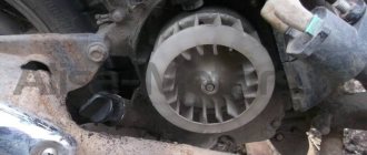
Photo report: How to check a scooter's generator?
Just like that, without minimal knowledge of electronics, at least at the school curriculum level (like mine) and a simple multimeter tester, you won’t be able to test the generator, don’t even dream about it. Before taking on such work, you should at least be able to use a tester and understand that current can be alternating or constant, know what an electrical impulse is and what resistance is. Do you know all this? Have you held a tester in your hands? If yes, then let's not hesitate.
Checking the functionality of the generator should begin with measuring the voltage that the generator itself must generate and transmit through wires to consumers. We look at where the wiring harness from the generator comes out of the engine - we move along it until we reach the connector with which the generator is connected to the on-board network of the scooter.
On the vast majority of scooters, the alternator connector looks something like the picture. In the common connector, there is one plug and two wires that are connected to the scooter’s on-board network through round terminals.
The plug combines the connectors of the two main windings of the generator: The working winding (yellow wire), which ensures the operation of the headlights, turn signals, lights and other consumers. And the control winding (white wire), the control winding provides voltage control in the main winding of the generator. That is, when the voltage in the operating winding of the generator increases above the specified limits, the relay-voltage regulator supplies current to the control winding of the generator, due to which the voltage in the operating winding of the generator drops to the specified limit. When the voltage drops, the reverse process occurs.
In this generator, the main windings are wound with thick copper wire on six coils.
The third winding of the generator, which is usually called high-voltage or inductive, and the magnetic induction sensor of the generator are connected to the scooter’s on-board network through round terminals.
High-voltage winding of the generator - ensures the generation of high alternating voltage (the voltage in this winding can reach 160 V or more), which directly enters the switch where it is rectified, then accumulated in the capacitor and at a certain moment in the form of a pulse is supplied to the ignition coil.
In this generator, the high-voltage winding is wound with a thin copper wire on two coils. The high-voltage winding coils are carefully insulated on the outside.
There are generators in which the high-voltage winding is wound on only one coil.
A small clarification: ignition systems in which a DC CDI type switch is installed, the high-voltage winding does not participate in the formation of a spark charge on the spark plug, so there is no point in checking it. Scooter manufacturers install a generator with a high-voltage winding, but do not use it (meaning ignition systems with a DC CDI switch). It's just wound on the generator and that's it. I will say more: due to the fact that the winding is not loaded with anything during operation of the generator, over time it simply burns out.
An example of a generator, on two coils of which a high-voltage winding that is not involved in operation is wound. I checked this winding - the tester showed an open circuit, which confirms the above.
The resistance of the generator's inducing winding is always greater than that of the other windings. The wire coming from the inducing winding of the generator is almost always red and black.
The magnetic induction sensor, when a special ledge on the generator rotor passes past it, generates an alternating pulse that opens a theristor through which the switch capacitor is discharged to the ignition coil.
Sensor in person
Ledge on the generator rotor
The wire coming from the magnetic induction sensor is almost always blue-white.
A small educational program: Traders and collective farm tusks, magnetic induction sensor of the generator, CDI ignition systems - called the Hall sensor. My dear ones... Maybe that's enough already. Where does this illiteracy come from? Magnetic induction sensor of the generator, CDI ignition system, namely this system is discussed in this article - has nothing to do with the hall sensor! And don’t listen to these hucksters and “gurus” who say the opposite...
The actual check itself
We switch the tester to the alternating current (ACV) measurement mode to a range of 200 V and no less. We remember that the voltage of the inducing winding can reach 160 V or more, so the measurement range of the voltage of the inducing winding must be at least 200 V.
We disconnect the plug and round terminals of the main harness - connect one probe of the tester to ground, connect the other to the terminal (black-red wire) of the inducing winding of the generator. Turn on the ignition and turn the engine with the starter. A fully operational pickup winding should produce approximately the following values.
The pulse generated by the sensor is very weak, therefore, we switch the tester to the alternating voltage (ACV) measurement mode in the 2 V range. Measuring the pulse from the sensor in a higher range may not give a result, since the tester may simply not catch it. For this purpose, use only a tester with a range in AC voltage measurement mode of no more than 2 V.
We do everything exactly the same as in the first example. The pulse from the sensor should produce approximately the following values.
By analogy with the first two examples, we measure the voltage in the working and control windings. We put the tester in the alternating voltage (ACV) measurement mode in the 200 V range and take measurements.
Well, we measured it. Do all windings generate current? Or not all. If any winding does not produce current, then whether you like it or not, you will have to remove the generator and check it in more detail. But if the windings generate a current of approximately the same magnitude as in the pictures, then this means that your generator is in perfect order. Something like this…
We lay the generator so that the terminals of the generator windings are accessible to you. We determine the ends of the terminals of all generator windings. Finding the ends of the windings is very simple: look at the color of the wire that is soldered to the terminal block and determine what kind of winding it is.
I have marked the ends of the windings here with arrows. I selected the arrows in color in accordance with the color of the wires soldered to the terminal block. The green arrow marks the terminal block on which the ends of all windings are soldered - this is the ground terminal block.
We switch the tester to the dialing mode, take any wire from the common harness, connect any tester probe to this wire, and with the second probe touch the terminal block to which this wire is soldered. The tester should beep and show zero resistance.
If the tester is “silent” and shows numbers instead of zeros, then this means that there is a wire break somewhere or poor contact between the end terminal and the wire. Inspect the wire carefully for a break and, if necessary, replace it with a new one. We check the remaining wires, including the sensor wire, using exactly the same principle.