How to check the generator on a scooter
Checking a scooter's generator is a fairly important and sometimes necessary procedure for every owner of this two-wheeled vehicle. Unfortunately, it can be difficult to establish its functionality, especially if you do not have deep knowledge in the field of electrical engineering, as well as the necessary tool - a multimeter tester .
If you have such a tool, then before checking the generator you will need to familiarize yourself with the concepts of alternating and direct current, voltage, electrical impulse and tester indicators. Let's move from words to action
To check the generator on a scooter, you need to remove the plastic around the engine, and then measure the indicators - first of all, the voltage . You need to remove the casing as carefully as possible, otherwise you will damage the fastening system.
Find the place where the bundle of wires comes out of the engine and move along it to the connector - the place where the generator is connected to the scooter’s on-board network. Then you will need to measure the resistance of the circuit that powers the generator coil. Disconnect the wiring from the generator and measure the resistance of the connector wires. In theory, the resistance in the coil should be from 80 to 150 Ohms. If during measurement deviations from these values are found, you should not immediately think about a malfunction.
Try removing the generator from the scooter and measuring the resistance of the coil itself by connecting the tester directly to it. When taking readings from the coil, carefully inspect the condition of its terminals - damage that leads to a decrease in resistance may be the cause.
If during diagnostics you find out that the coil resistance readings are within the normal range, then the cause of the malfunction most likely lies in the wires themselves, coming from the coil or at the output points. Check the wiring and make sure there are no shorts in the wires.
If, as a result of this, no malfunctions were identified, you should also measure the variable resistance at the terminals from the ignition unit. If, after checking the generator on the scooter, you do not find any problems, the reason for the poor operation of the generator lies in the ignition unit.
Setting up and testing the scooter
Check the power interrupt switch. This safety feature "interrupts" engine power when you apply the brakes. If your scooter does not work after adjusting the brakes, then the problem lies in this unit.
Adjustment procedures may vary depending on the scooter model. You can usually loosen the brake adjustment tension by turning the brake adjuster built into the handle toward the lever. This releases the tension on the adjustment and safety switch. Check the owner's manual or contact the motor manufacturer.
If this setup doesn't work, there is an easy way to test the generator. Disconnect it from the controller, then try to start the scooter. If the problem is with the switch, then the scooter will only work when the brake lever switch is disabled. Make sure the power switch is turned on.
Checking the scooter fuse
If the scooter uses a fuse, look at the inside of the fuse to make sure it hasn't blown. The fuse may need to be removed from the scooter and held up to a light source so you can determine whether it is blown or not.
fuse in scooter
For scooters that use an automatic fuse, press or flip the automatic switch to check its functionality.
Automatic power switch
Perform a test using a multimeter. Sometimes fuses burn out in a hard-to-reach place. Also, circuit breakers can mechanically reset but still not work. Testing the continuity of a fuse or circuit breaker using a multimeter is the best way to determine whether it is working or not.
Also try charging the battery for 8 hours. Electric scooters that have not been charged for more than 3 months will have their batteries partially discharged. Try charging the battery for 8 hours and then see if that helps.
Common causes of problems with scooter generators
In conclusion, it is worth noting that the failure of a scooter generator is one of the most common problems faced by owners of two-wheeled vehicles. If a malfunction occurs, you may encounter external signs such as a poor battery charge, a weak spark, or some problems with the electrical system. Typically, the reason for the incorrect operation of the generator is:
- Short circuit;
- Wire wear;
- A sharp decrease in the magnetization of the generator rotor, etc.
Before repairing the generator, you must carry out diagnostics and find out the cause of the malfunction, and only then begin repairs or take the device to a workshop.
Ignition circuit components
The ignition circuit is an important part of the scooter's electrical system, without which it simply will not work without proper assembly. The circuit includes a coil, a spark plug, a switch, a generator, and a CDI ignition module. The latter looks like a small block, on one side it is plastic, on the other it is filled with compound. It is for this reason that when a unit fails, it is completely replaced without trying to disassemble it.
The CDI module has outputs for connecting five conductors. It is usually located quite close to the battery, can be mounted on the scooter frame or have a special cell. Most often, the CDI unit is located closer to the bottom of the vehicle, so it is not easy to reach. Without this element the system will not work.
Relay regulator
The relay regulator is colloquially called a stabilizer. This element is needed in order to rectify the voltage and stabilize it to the required level, which is suitable for the operation of the scooter’s electrical appliances. In Chinese and many Japanese models you need to look for it in the front of the vehicle, usually under the fairing. During operation, the radiator of the part becomes very hot, so it is placed where it can receive air cooling.
During operation, the generator produces alternating current, which is supplied first to the relay-regulator, and then moves on. The relay converts alternating voltage to direct voltage, in addition, it stabilizes the voltage to 13.5-14.8 Volts. If the voltage is less, the battery will not be able to charge; if it is more, there is a high risk of failure of the electrical system.
The regulator usually has 4 wires. They differ in color; in a standard diagram, the green wire is always ground. Red is under constant voltage. White supplies the regulator relay with the voltage supplied by the generator: this is alternating current. The yellow wire also goes from the generator to the relay regulator. The relay converts the voltage, turning it into a pulsating one. After this, the voltage goes to lighting fixtures, which are the most powerful consumers. Some models have an illuminated dashboard, additional lighting, running lights or other types of suspension. All this is powered by the same wire.
How to check the generator on a scooter
August 7, 2014 at 5:28 pm by Pasha
If the scooter has problems with a poor battery charge, a weak spark, or there is a breakdown in the electrical system, then it is highly likely that the vehicle's generator will have to be repaired.
There may be several reasons for the failure:
1. Short circuit;
2. Violation of the integrity of the wire;
3. A sharp drop in the magnetization of the generator rotor.
The decrease in rotor magnetization is due to objective factors, typical of which are:
* The scooter enters a high magnetic field area.
Under these impacts, a significant drop in the output current of the generator often occurs, which leads to the impossibility of further operation of the scooter. But a more objective picture emerges only when a competent diagnosis is carried out.
Checking the serviceability of the scooter generator
If a scooter generator requires repairs and its device does not allow you to assess the breakdown with the naked eye, a control device - a multimeter - can help. It is the tester that will show real surges in voltage amplitude and identify the direction for troubleshooting.
Diagnostics is carried out in several stages.
Stage 1. Checking the generator output voltage.
1. Connect the tester to the disconnected connectors;
2. With the engine turned on at minimum speed, evaluate the result. Satisfactory performance is within 5 V.
Stage 2. Checking the output voltage of the switch using a tester with a voltage amplitude reading.
1. Connect the switch wires to the generator stator wiring;
2. Disconnect the block from the terminal of the primary ignition coil;
3. We close one terminal to the main wire of the ignition coil, the second to the engine ground.
4. When starting the engine, we check the output voltage using a tester in the “constant current” mode;
5. We return the switch wire leading to the coil to its place and check the average output voltage.
6. The required indicator is about 200V.
Stage 3. Checking the battery condition.
This is the simplest operation when diagnosing and repairing a generator on a scooter :
Electrics and electrical equipment of a scooter
Dedicated to all owners of Chinese scooters...
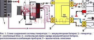
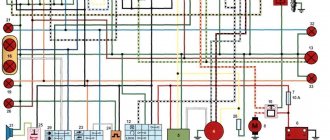
To begin with, I would like to present a wiring diagram for a Chinese scooter.
Since all Chinese scooters are very similar, like Siamese twins, their electrical circuits are practically no different.
The diagram was found on the Internet and is, in my opinion, one of the most successful, since it shows the color of the connecting conductors. This greatly simplifies the diagram and makes it more comfortable to read.
(Click on the image to enlarge. The image will open in a new window).
It is worth noting that in the electrical circuit of a scooter, just like in any electronic circuit, there is a common wire . On a scooter, the common wire is the minus ( - ). In the diagram, the common wire is shown in green . If you look more closely, you will notice that it is connected to all the electrical equipment of the scooter: headlight ( 16 ), turn relay ( 24 ), instrument panel backlight lamp ( 15 ), indicator lamps ( 20 , 36 , 22 , 17 ), tachometer ( 18 ), fuel level sensor ( 14 ), horn ( 31 ), tail light/brake light ( 13 ), start relay ( 10 ) and other devices.
First, let's go over the main elements of the Chinese scooter circuit.
Egnition lock.
Ignition switch ( 12 ) or “Main switch”. The ignition switch is nothing more than a regular multi-position switch. Even though the ignition switch has 3 positions, the electrical circuit uses only 2.
When the key is in the first position, the red and black wires are connected. In this case, the voltage from the battery enters the electric circuit of the scooter, the scooter is ready to start. The fuel level indicator, tachometer, sound signal, turn relay, and ignition circuit are also ready for operation. They are supplied with power from the battery.
If the ignition switch malfunctions, it can be safely replaced with some kind of switch like a toggle switch. The toggle switch must be powerful enough, because the entire electrical circuit of the scooter is, in fact, switched through the ignition switch. Of course, you can do without a toggle switch if you limit yourself to short-circuiting the red and black wires, as the heroes of Hollywood action films once did.
1 is shorted to the housing (common wire). In this case, engine operation is blocked . Some scooter models have an engine stop button ( 27 ) to block the engine, which, like the ignition switch, connects the white- black and green (common, body) wires.
Generator.
The generator ( 4 ) produces alternating electric current to power all current consumers and charge the battery ( 6 ).
There are 5 wires coming from the generator. One of them is connected to a common wire (frame). The alternating voltage is removed from the white wire and supplied to the relay regulator for subsequent straightening and stabilization. The yellow wire removes voltage, which is used to power the low/high beam lamp, which is installed in the front fairing of the scooter.
Also in the design of the generator there is a so-called hall sensor . It is not electrically connected to the generator and there are 2 wires coming from it: white- green and red - black . The hall sensor is connected to the CDI ignition module ( 1 ).
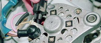
Relay regulator.
Regulator relay ( 5 ). People may call it a “stabilizer”, “transistor”, “regulator”, “voltage regulator” or simply “relay”. All these definitions refer to one piece of hardware. This is what the relay regulator looks like.
The relay regulator on Chinese scooters is installed in the front part under a plastic fairing. The relay-regulator itself is attached to the metal base of the scooter in order to reduce the heating of the relay radiator during operation. This is what the relay regulator looks like on a scooter.
In the operation of a scooter, the relay regulator plays a very important role. The task of the relay regulator is to convert the alternating voltage from the generator into direct voltage and limit it to 13.5 - 14.8 volts. This is the voltage required to charge the battery.
The diagram and photo show that there are 4 wires coming from the relay-regulator. Green is the common wire. We have already talked about it. Red is the output of positive DC voltage 13.5 -14.8 volts.
The regulator receives alternating voltage from the generator through the white wire to the relay. Also connected to the regulator is yellow wire coming from the generator. It supplies the regulator with alternating voltage from the generator. Due to the electronic circuit of the regulator, the voltage on this wire is converted into a pulsating one, and is supplied to powerful current consumers - the low and high beam lamps, as well as the dashboard backlight lamps (there may be several of them).
The supply voltage of the lamps is not stabilized, but is limited by the relay regulator at a certain level (about 12V), since at high speeds the alternating voltage supplied from the generator exceeds the permissible limit. I think those who have had their dimensions burned out due to malfunctions of the relay-regulator know this.
Despite all its importance, the device of the relay regulator is quite primitive. If you pick apart the compound with which the printed circuit board is filled, you will find that the main relay is an electronic circuit consisting of a thyristor BT151-650R , a diode bridge on 1N4007 , a powerful diode 1N5408 , as well as several wiring elements: electrolytic capacitors, low-power SMD transistors, resistors and a zener diode.
Due to its primitive circuitry, the relay-regulator often fails. Read about how to check the voltage regulator here.
Photo report: How to check a scooter's generator?
Just like that, without minimal knowledge of electronics, at least at the school curriculum level (like mine) and a simple multimeter tester, you won’t be able to test the generator, don’t even dream about it. Before taking on such work, you should at least be able to use a tester and understand that current can be alternating or constant, know what an electrical impulse is and what resistance is. Do you know all this? Have you held a tester in your hands? If yes, then let's not hesitate.
Checking the functionality of the generator should begin with measuring the voltage that the generator itself must generate and transmit through wires to consumers. We look at where the wiring harness from the generator comes out of the engine - we move along it until we reach the connector with which the generator is connected to the on-board network of the scooter.
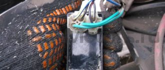
On the vast majority of scooters, the alternator connector looks something like the picture. In the common connector, there is one plug and two wires that are connected to the scooter’s on-board network through round terminals.
The plug combines the connectors of the two main windings of the generator: The working winding (yellow wire), which ensures the operation of the headlights, turn signals, lights and other consumers. And the control winding (white wire), the control winding provides voltage control in the main winding of the generator. That is, when the voltage in the operating winding of the generator increases above the specified limits, the relay-voltage regulator supplies current to the control winding of the generator, due to which the voltage in the operating winding of the generator drops to the specified limit. When the voltage drops, the reverse process occurs.
In this generator, the main windings are wound with thick copper wire on six coils.
The third winding of the generator, which is usually called high-voltage or inductive, and the magnetic induction sensor of the generator are connected to the scooter’s on-board network through round terminals.
High-voltage winding of the generator - ensures the generation of high alternating voltage (the voltage in this winding can reach 160 V or more), which directly enters the switch where it is rectified, then accumulated in the capacitor and at a certain moment in the form of a pulse is supplied to the ignition coil.
In this generator, the high-voltage winding is wound with a thin copper wire on two coils. The high-voltage winding coils are carefully insulated on the outside.
There are generators in which the high-voltage winding is wound on only one coil.
A small clarification: ignition systems in which a DC CDI type switch is installed, the high-voltage winding does not participate in the formation of a spark charge on the spark plug, so there is no point in checking it. Scooter manufacturers install a generator with a high-voltage winding, but do not use it (meaning ignition systems with a DC CDI switch). It's just wound on the generator and that's it. I will say more: due to the fact that the winding is not loaded with anything during operation of the generator, over time it simply burns out.
An example of a generator, on two coils of which a high-voltage winding that is not involved in operation is wound. I checked this winding - the tester showed an open circuit, which confirms the above.
The resistance of the generator's inducing winding is always greater than that of the other windings. The wire coming from the inducing winding of the generator is almost always red and black.
The magnetic induction sensor, when a special ledge on the generator rotor passes past it, generates an alternating pulse that opens a theristor through which the switch capacitor is discharged to the ignition coil.
Sensor in person
Ledge on the generator rotor
The wire coming from the magnetic induction sensor is almost always blue-white.
A small educational program: Traders and collective farm tusks, magnetic induction sensor of the generator, CDI ignition systems - called the Hall sensor. My dear ones... Maybe that's enough already. Where does this illiteracy come from? Magnetic induction sensor of the generator, CDI ignition system, namely this system is discussed in this article - has nothing to do with the hall sensor! And don’t listen to these hucksters and “gurus” who say the opposite...
Design and principle of operation of a scooter generator
To the average person who is not experienced in electrical matters, a scooter generator may seem like a very complicated device.
This is partly true: electric current is an invisible thing to the eye, and if we can see or touch mechanical faults, then we can only guess about faults in the electrics of a scooter or identify them using special measuring devices. However, “it’s not the Gods who burn the pots” and if a person has a desire for something, then this article will be a good help, but for those who don’t want anything, there’s no point in continuing.
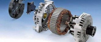
The scooter generator is a flywheel type generator with permanent magnet excitation. This type of generator is used on the vast majority of scooters, as well as mopeds and small motorcycles.
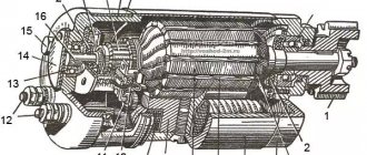
Designation of the main elements of the generator
The scooter generator consists of a rotor (in collective farm language - “anchor”) and a stator. The rotor is mounted directly on the crankshaft and while the engine is running, the rotor rotates around the stator coils
The stator is attached directly to the engine crankcase. And while the engine is running it remains motionless. The stator is a metal base made of several plates of special transformer iron. On the base of the stator there are special projections (coils) on top of which a copper wire is wound in a strictly defined order - forming the generator windings.
Depending on the generator model, there may be two or three windings. The generator shown below has three windings: supply, control and high-voltage
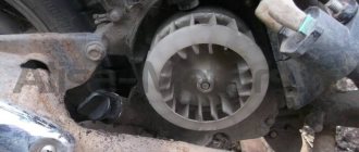
Permanent magnets are installed on the inner surface of the rotor. Magnets have different polarities. The magnets in the drain are covered with a lid; if you remove it, you can see them
Each magnet forms a static (constant) magnetic field around itself. In turn, the field of each magnet will be different: blue is negative (“north”), red is positive (“south”)
If we insert the stator into the rotor in the same way as is done on the engine, then we will see that the stator coils will be in the magnetic field of the magnets located next to them
After we start the engine, the rotor magnets will begin to rotate around the stator coils. During the rotation of the rotor, magnets of different polarities will approach the coils, which always stand still, and the field in which the coils are located will change at a very high speed. Due to the rapid change of magnetic fields, magnetic induction will occur in the generator coils and the generator will begin to generate electric current.
Current is good. But the current of a generator with excitation from permanent magnets is not a constant value and directly depends on the engine speed: the higher the engine speed, the more often the field of the coils changes - the induction increases and, as a result, the voltage in the coils increases. So it turns out that at idle engine speed the generator voltage will be 8-10V, and at maximum 60-70V.
In order to stabilize the generator voltage to specified limits, a special generator voltage regulating module was introduced into the scooter’s power supply system. That’s what it’s called: generator relay regulator
The principle of operation of the relay regulator is very simple: there are three windings on the generator stator: supply, high-voltage and control. The power winding is the main one and is designed to power the lights, sound signal and charge the battery.
The control winding is auxiliary and if the voltage in the supply winding increases, the relay-regulator supplies voltage to the control winding - the induction is disrupted and, as a result, the voltage in the supply winding of the generator drops.
When the voltage decreases, the opposite happens: the relay-regulator stops supplying current to the control winding, induction is restored, and the voltage in the supply winding increases.
The control and auxiliary windings of the generator are wound on the same coils
READ How to connect a frequency converter to a DC motor
The high voltage winding is wound on individual coils or coil. The high-voltage coil is needed to form a spark on the spark plug and is only partially related to the generator. Rather, it relates to the ignition system, and this is a separate module and has little to do with the operation of the generator
Another auxiliary module of the generator is a load resistor. It is needed to ensure that the generator does not operate without load. For devices that generate current, working without a load is like death. The designers foresaw this possibility in advance and, in order to prevent the generator from running idle, they slightly loaded the supply winding onto the resistor
In addition to the elements described above, the scooter’s energy supply system includes an ignition sensor, which, at the right moment, ensures the formation of a spark at the spark plug.
This module is the same generator only in miniature and it works exactly on the same principle
On the outside of the rotor there is a small magnet in the form of a rectangular protrusion. This magnet, just like its larger brothers, forms a constant magnetic field around itself, and what happens next, you probably already guessed: while the engine is running, the field passes through the sensor coil and a small current is generated in it, which goes directly to the switch, controlling the torque in it sparking
Source
How to check a scooter's generator?
9 years on the site user #266100
In general, I removed the generator, I had a nightmare on the winding coils, everything was covered in fine sand and seemed to have very fine dust! Why did I go there, the spark was gone, I changed the spark plugs, I bought a new coil, I rang the wiring, I put the camutator on another scooter, it started, so there was only one generator left! So my question is how to check it, if you ring it, how much resistance should it show, and There is also a little black little thing with a separate magnet, how can I check it?
How to ring a generator
How to ring a generator
05 Dec 2011, 14:28
Re: How to ring a generator
05 Dec 2011, 17:44
Re: How to ring a generator
06 Dec 2011, 14:15
Re: How to ring a generator
06 Dec 2011, 17:33
Re: How to ring a generator
07 Dec 2011, 09:03
Re: How to ring a generator
08 Dec 2011, 22:22
Re: How to ring a generator
14 Dec 2011, 07:54
Re: How to ring a generator
14 Dec 2011, 20:25
Between which two wires are you measuring? download/file.php?id=643&mode=view Here is the diagram, measure black-red and black. Resistance with the engine stopped, voltage in AC mode when the crankshaft rotates (best of all, with a kickstarter - one turns, the other watches). The CDI is more likely to die than the alternator. If the measurement is after the diode, then you can measure in constant mode.
Re: How to ring a generator
16 Dec 2011, 06:33
here from the MOTO.com.ua forum
I’ll describe how to check everything without disassembling the moped. We remove the switch chip and take a tester, put one ohm probe to ground and poke the other into the connector: 1. the red wire (power coil) should show about 300 ohms. 2. yellow (woman) a couple of ohms. The main thing is that it rings. 3. blue (spark sensor) about 150 ohms, it seems. 4.green (mass) clear Oom. 5. black (silencer) 0 ohm. when the ignition is off, when the ignition is on, open circuit (infinity). The accuracy of the readings is not important, the main thing is not an open or short circuit, but where such a discrepancy is observed along that wire and we go to the culprit. The third is not given, but if there is a spark, then there is no, here you can search for a long time: 15_badgrin: One homosapies’ moped stalled for no reason at all: 27_dash: if you start poking around, it will start and even chop it with an ax : 15_badgrin: . The droplets gave me an idea corrosion on the engine. Electrolyte dripped from the battery and got into the gene chip, under the cambrics it rotted.