Generator set design
The VAZ-2112 generator consists of covers - front and rear. They are made of aluminum alloy and have special sockets where bearings are installed. On the back cover there is a terminal that is used to connect the battery. It also has a connector. Through it, voltage is supplied to the excitation winding. There is a capacitor on the back cover - it serves to suppress electromagnetic interference. There are places on the device for installing and securing brushes.
The core cylinder in this generator is made of transformer iron. Inside it there are special grooves in which the winding is neatly laid. Also on the cylinder there are leads for connection to the rectifier unit. The covers are screwed to the stator using bolts. The shaft, which acts as a rotor, has an excitation winding. It is connected to copper rings. A special groove is made at the front end of the shaft, which serves to install the drive pulley. The brushes are made in one piece, which is combined with the generator relay. It is housed in a durable metal case and securely attached to the brush holder. The back cover inside holds the diode unit - it includes 6 main elements and three additional ones. They are mounted on aluminum semicircular plates, due to which the diodes are cooled more efficiently. In the car's operating manual there is a diagram with which you can figure out how the VAZ-2112 generator works.
It is also used for repair work.
Instructions for repairing the Lada 2110 generator, the procedure for assembling and disassembling the Lada 2111 car generator, checking the VAZ 2111, VAZ 2112, VAZ 2110 generator. Diagnostics of the electrical equipment of the Lada 2110 car. Instructions for troubleshooting the lighting system. Repair of the generator and starter of the Lada 2111. Diagram of the Lada 2112 car.
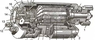
Generator 1 — casing 2 — “B+” terminal for connecting consumers 3 — interference suppression capacitor 2.2 μF 4 — common terminal of additional diodes (connected to the “D+” terminal of the voltage regulator) 5 — holder of positive diodes of the rectifier unit 6 — holder of negative diodes of the rectifier unit 7 — positive diode 8 — negative diode 9 — voltage regulator 10 — back cover 11 — coupling screw 12 — front cover 13 — stator winding 14 — spacer ring 15 — - front bearing of the rotor shaft 16 - pulley 17 - nut 18 - rotor shaft 19 - cone washer 20 - washer 21 - beak-shaped rotor pole pieces 22 - stator core 23 - bushing 24 - rotor winding 25 - - rear rotor bearing 26 —- bearing sleeve 27 — slip rings 28 — brush holder 29 — stator winding terminals 30 — additional diode 31 — terminal “D” (common terminal of additional diodes) Generator – synchronous AC electric machine with electromagnetic excitation and built-in rectifier based on silicon diodes. The generator rotor is driven into rotation from the engine crankshaft pulley (damper) by a poly-V belt.
Generator Specifications
| Characteristic | Meaning |
| Maximum output current (at 13 V and 6000 rpm), A | 80 |
| Voltage, V | 13,2–14,7 |
| Engine-generator gear ratio | 01:02,4 |
| Direction of rotation (drive side) | Right |
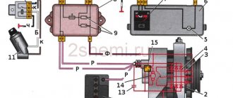
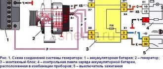
The stator and covers of the VAZ 2112 generator are secured with four screws. The rotor shaft rotates in bearings installed in the covers. The lubricant placed in the bearings at the factory is designed to last the entire service life of the generator. The rear bearing is pressed onto the rotor shaft and is pressed by the rear cover through a plastic sleeve. The front bearing is pressed and rolled into the front cover and can only be replaced together with it. Its inner race, together with the spacer ring and washer, is clamped by a nut between the pulley and the step on the rotor shaft. The back of the VAZ 2112 generator is closed with a plastic casing with latches. The generator stator contains a three-phase winding made in a star configuration (the terminals of the phase windings have a common point). The second ends of the phase windings are connected to a rectifier bridge consisting of six silicon diodes (valves) - three “positive” and three “negative”. The valves are pressed into two horseshoe-shaped aluminum holder plates in accordance with the polarity (positive and negative - on different plates); one of the plates also contains three additional diodes, through which the excitation winding of the generator is powered after starting the engine. The plates are combined into a rectifier unit mounted on the back cover of the VAZ 2111 generator (under a plastic casing). The excitation winding is located on the generator rotor, its leads are soldered to two copper slip rings on the rotor shaft. Power is supplied to the field winding through two carbon brushes. The brush holder is structurally combined with the voltage regulator and is mounted on the back cover of the generator. The voltage regulator is non-separable; if it fails, it is replaced. To protect the on-board network from voltage surges during operation of the ignition system and reduce interference with radio reception, a capacitor with a capacity of 2.2 μF (±20%) is connected between the terminals of the “positive” and “negative” valves (between the “+” and “ground” of the generator) on the rectifier block. When the ignition is turned on, voltage is supplied to the excitation winding of the VAZ 2110 generator (terminals “D” of the generator and “D+” of the regulator) through the control lamp in the instrument cluster (the lamp is lit). After starting the engine, the excitation winding is powered by additional diodes of the rectifier unit (the control lamp goes out). If the lamp lights up after starting the engine, this indicates a malfunction of the generator or its circuits. The “minus” of the battery should always be connected to the “ground” of the VAZ 2110 car, and the “plus” to the “B+” terminal of the generator. Switching back on will lead to breakdown of the generator valves. It is not recommended to disconnect the battery when the generator is running (especially on engines equipped with an injection system). The resulting voltage surges in the on-board network can damage the electronic components of the circuit. The generator valves (and other devices in the vehicle’s on-board network when the generator is connected) should be checked at a voltage no higher than 14 V; a higher voltage (for example, when checking with a megger) can cause damage to the valves. If it is necessary to check the insulation of windings with high voltage, the VAZ 2110 generator should be removed, and the winding terminals should be disconnected from the rectifier unit and voltage regulator. Generator connection diagram 1 — battery 2 — generator 3 — relay and fuse box (mounting block) 4 — ignition switch
Principle of operation
The rotor, whose main task is to create a magnetic field, is a shaft on which the excitation winding is located. Each half of it is placed in special pole parts. The slip rings supply current to the winding. The rotor rotates due to a belt drive from the drive. The stator consists of a core and a winding. Here, alternating current is generated, which is sent through the rings further along the electrical network. However, it must first be removed from the frame. In order to supply current to the rings, a brush assembly is used. Then comes the rectifier unit, which converts the alternating sinusoidal voltage generated by the generator. In different cases, different circuits for connecting the excitation windings are used. For example, another separate pair is applied. Current simply cannot flow through the battery if the engine is not running. When connecting the winding in a star configuration, you can increase the generator power by 15%. The generator relay maintains the voltage of the device within the specified limits. It changes the frequency and duration of electrical current pulses. A relay is a set of several sensors and actuators. Their task is to determine how long the field winding should be in the network. If the relay is faulty, then an unstabilized voltage will be supplied to the battery.
What is a generator for?
As you know, a generator is a vehicle device that provides electricity to various elements, converting mechanical energy into current. This is a kind of source of energy supply, which often replaces a stable central power supply. In other words, a car alternator charges the battery while the engine is running.
Basic information about the generator
So:
- The generator is located on the VAZ 2112, usually in the front part of the engine.
- Driven by the crankshaft.
As a rule, there are two types of generators, two types. Traditional generator and compact. These types differ from each other in the fan layout, housing structure, pulley and much more. But their general details remain the same:
- rotor;
- stator;
- brush assembly;
- voltage regulator;
- rectifier block.
Note. All of the above elements are placed in a closed housing.
Let's consider each element of the generator separately.
Rotor
This part is designed to create a rotating magnetic field:
- The rotor shaft has an excitation winding, which is specially placed in two pole halves.
Note. Each of these pole halves has 6 projections.
- There are two contact rings on the rotor shaft, through which the field winding is powered.
Note. As a rule, these rings are made of copper, and sometimes of steel or brass.
Stator
This element serves to create alternating electric current:
- The stator combines a winding and a metal core, which consists of steel plates.
Note. There are 36 slots in the core, into which three windings are placed. Together they form a three-phase connection. Frame
The generator housing is an element that consists of two covers. The front cover is located on the generator drive pulley side, and the rear cover is located on the slip ring side.
Brush unit
Thanks to this unit, current is supplied to the slip rings. Two graphite brushes, springs and a brush holder - that’s all that makes up the brush assembly.
Rectifier block
This element converts sinusoidal voltage into DC voltage. The rectifier unit consists of heat sink plates and diodes.
Voltage regulator
Designed to maintain voltage in the generator. To date, several designs of these same elements are known:
- hybrid voltage regulators;
- integrated voltage regulators.
Specifications
The VAZ-2112 generator has the following technical parameters.
Thus, the voltage that is formed on the excitation winding can vary from 13.2 V to 14.7 V. The generator itself is capable of generating a current of up to 80 A. The tension of the drive belt is such that with a pressure weighing 10 kg the deflection will be no less than 8 mm.
Maintaining a generator on a VAZ-2112 car
It is important to service this element on time - it has a large margin of reliability, but sometimes if the service is untimely, it is necessary to repair the car generator. The first step is to clean the outside surfaces of the device.
In addition, during service activities, they check whether the generator is securely fastened. The voltage regulator also needs checking. Experts recommend checking the drive belt. If it is loose, the system will not function correctly. It is recommended to check the VAZ-2112 alternator belt every 10 thousand km of the car - there should be no defects on its surface. Next, check the condition of the bearings. During this operation, it is necessary to remove the belt and rotate the rotor of the device by hand. If during rotation you feel play or jamming during movement, extraneous noise or any other sounds, the bearings are out of order and need to be replaced. For a VAZ-2112 generator, the price of which is about 4 thousand rubles, such parts can be found in any store or market.
Common malfunctions (signs) of the VAZ 2110 generator
- The device does not perform its main function, that is, it does not produce current. In this case, the car is driven only by the battery. Moreover, in this case you will not be able to travel far.
- The drive belt is spinning.
- The generator brushes are faulty.
- The rotor clings and touches the stator.
- There is no wire contact with the battery.
- The device begins to make a lot of noise.
- The battery does not charge while driving.
All these signs are very specific and only an experienced driver can identify them. However, if you have even slight doubts about the performance of the generator of VAZ 21099, 2109, 2110 cars.
Possible faults
Like all other systems in a car, the alternator can also fail. Sometimes repairs can be made and the device will work again. But in case of some malfunctions, only replacing the VAZ-2112 generator will help.
Diagnostics of this unit is performed when increased noise occurs during operation. Often noise occurs due to severe wear of bearings. But often only the bearing located in the front cover fails. It is subject to increased radial loads, so it does not last long. If the drive belt is too tight, this will also affect the rate of bearing wear.
Generator bearing replacement process
General view of the front and rear bearing of the generator
Existing play indicates that the bearing has indeed failed.
So, let's consider the step-by-step process of replacing a product with a VAZ-2112.
- We place the car on a pit or overpass. The main thing is that there is access from below.
- We dismantle the “minus terminal”.
- Remove the generator belt.
Pull the alternator belt through the slot - To further carry out the work, you will need to dismantle the generator itself.
- Disconnect the appropriate wires to the generator.
Disconnect all wires that go to the generator - Loosen the nut that holds the tension bolt.
- Remove the adjusting bolt.
Unscrew and remove the generator adjusting bolt - Remove the lower engine protection.
We dismantle the engine protection - Unscrew the 2 lower mounting bolts.
- We are dismantling the generator.
It comes out through the bottom. We unscrew the fastenings and dismantle the generator - When the generator is in your hands, you can put it on the table. Now, you can proceed directly to the repair.
- Having blocked the rotor from turning, remove the pulley.
- We dismantle the casing.
To do this, you need to pull back the latches. Block the rotor and unscrew the pulley - Remove the front and back covers.
Generator disassembly diagram - Now feel free to move on directly to replacing the bearing.
Using a hammer, knock out the rotor from the cover along with the bearing - The product can be dismantled using a special puller, or simply by knocking it out of its seat.
- Installation is carried out in reverse order.
Replacing bearings
- We clean the load-bearing elements well.
Disassembled generator - Apply sealant to the seat.
Applying sealant - We press in new bearings.
One bearing is pressed in - The most difficult part is to press in the inner bearing.
First we remove it. There is a puller, but if it is not available, then we use a regular key. Removing a bearing without using a puller - We put on a new one.
New bearing ready for use
Next, we assemble the generator and install it back!
>
What bearings are on the VAZ-2112 generator?
The choice of bearing should be taken seriously, since the stable voltage in the on-board network, as well as the wear of the generator itself, depends on this part.
Since there are 2 bearings in the unit - front and rear, each of them has its own markings and dimensions.
So, the front ones are marked - 6302 or 6303, but the rear ones - 6202 or 6203.
Generator front and rear bearings
Since there are many fakes on the automotive spare parts market, especially with regard to bearings, when choosing, you should pay special attention to the production of this product. The wear of many other generator parts will depend on the quality.
Therefore, it is recommended to check the availability of a quality certificate, as well as the presence of markings and holograms.
Original
6303-10B is the original catalog number of the generator bearing for the 10 series of Lada cars produced by AvtoVAZ. The average cost of a product is up to 150 rubles.
Analogs
Not original bearings, strip, and plug. Vologda bearings VBF
In addition to the original, you can buy a substitute product. Of course, now bearings can be selected depending on the size or number, but manufacturers of analogues still decided to produce high-quality products for cars.
| Manufacturer's name | Catalog number | Price |
| F.A.G. | 6303 | 450 |
| Nachi | 6203ZZ | 150 |
| NTN | 6203ZZ | 180 |
| Koyo | 6303C3 | 200 |
| SNR | 6203.ZZ | 400 |
There are several reasons for generator bearing failure:
>
- Wear. Like any part, the generator bearing fails during operation.
- Violation of the rules of operation and maintenance will lead to the product failure.
- External factors such as dirt, salt and road chemicals lead to the part being subject to increased wear.
- Poor quality can cause premature failure.
- Lack of lubrication.
The grease may have dried out over time. The lubricant is almost invisible
Electrical faults: diagnostic methods
Electrical problems in the operation of a generator can be identified based on several factors. So, among the popular symptoms are lack of charging, reduced charging voltage, or vice versa – increased. Without a multimeter, these breakdowns are determined by their main symptoms. So, the battery charge lamp on the instrument panel will light up or blink. Also, when the engine is running, the headlights shine very dimly, and the windshield wipers operate at a slow speed. Increased voltage will be indicated by boiling electrolyte in the battery and very bright headlights.
Superficial diagnostics can be performed without dismantling work. For testing you will need a multimeter. You need to measure the voltage at the battery terminals while the engine is running. If the device shows 12 V, the generator is not charging the battery. If the multimeter outputs below 14 V with all electrical equipment turned off, then the charge level is insufficient. Experts do not recommend testing the generator by removing the positive contact of the battery. This may damage the relay.
How to remove a generator on a VAZ-2112
For a more serious check, the device must be removed. The generator is held on a bracket on the engine block. To dismantle the installation, you will need keys 10 and 13, an open-end wrench 17, as well as a pry bar and socket 15.
The first step is to remove the terminals from the battery. Then loosen and remove the belt, and then dismantle the belt tensioner mechanism. Next, the wires are disconnected and the connectors are disconnected. The device is held in place by a long bolt and nut. It's not that easy to remove. Therefore, first unscrew the brackets on the motor block with a head. They are located at the back of the unit. Then the generator is deployed, which will help to easily unscrew the axle mount. It is pulled out together with the bushing, and then the axle is knocked out of the bracket.
Brush unit malfunctions
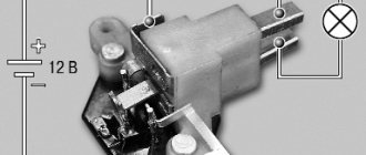
To check the brush assembly, you will need a power source, as well as any 12 V lamp. The power source is connected to the voltage regulator, the lamp is connected to the brush - it should light up. When the input voltage rises to 15 volts, the light goes out. If the lamp burns at a higher voltage, then repair of the VAZ-2112 car generator is necessary. The relay needs to be replaced. As for the brushes themselves, their malfunctions are indicated by a lack of battery charge, too low voltage in the car network, or unstable charging voltages.
The length of the brush should be more than 5 mm. If it is smaller, they need to be replaced. You can also move them slightly in the grooves to check the brushes. Working brushes move freely. If they hang, it is recommended to lubricate them. It is also worth making sure that the slip rings are in good condition - they are checked for wear. If there are marks, the rings are sanded with fine sandpaper. After replacing the brushes, the generator will immediately begin to operate normally. It is important to monitor how the device works and regularly service the VAZ-2112 generator - the price of the unit is low, but with high-quality service, only the brushes will need to be changed.
Do-it-yourself repair of a VAZ 2110 or VAZ 2112 generator
Disassembly: 1) First, remove it (How to remove the generator, read the article: “Replacing the generator on a VAZ 2110 or VAZ 2112”), then bend the three latches on the sides that secure the plastic cover, thanks to which dirt and water do not particularly get into the generator , after the latches are bent (Just do not break them), remove the cover from the generator and set it aside, as shown in the small photo.
2) Then unscrew the two side screws that secure the voltage regulator to the generator (The screws are indicated by red arrows, and the regulator itself is blue) and then remove the regulator from the generator, but only when you remove it, disconnect the wiring from it as shown in the photo in the corner shown, otherwise the regulator simply will not be removed from the car generator.
Note! After the voltage regulator and the brushes located on it have been removed, do not go further yet because there is no point, since if the brushes are not working properly, then the regulator can be replaced (It comes complete with brushes) and move on, it will just take a lot to disassemble the generator a lot of time and maybe even a whole day, if normal tools are not at hand, so when the regulator with brushes is removed, check it and to do this, connect a 12-volt test lamp to the regulator brushes, and supply current from the battery to the regulator itself exactly as it is shown in the photo under number 1, so that you understand how to supply current, we will explain this to you in a nutshell, in general, take a wire and attach it to the negative terminal of the battery and connect it to the brush holder body (see photo 1), then another wire is taken and connected to the plus terminal of the battery and to the plus terminal on the brush holders (Again, see the diagram in photo 1), after the operation, the control lamp, which at this time should be connected to the brushes, will definitely light up, if it doesn’t light up then the regulator is faulty, carry out exactly the same operation with this regulator, but only in this case, supply it with a current not of 12 Volts, which the rechargeable battery usually produces in a charged state, but of 15-16 Volts (This current is usually produced by the same rechargeable batteries, but only when the car is started and running, that is, the battery generator usually supplies a current of about 14.5 Volts, provided that the generator is strong and all devices are turned off in the car’s on-board network, you can check with what power the battery is charging using voltmeter), so when this current is applied, the lamp must go out, otherwise the voltage regulator must be replaced with a new one. In addition to these operations, also check how much the brushes protrude from the voltage regulator (see. photo 2, they should not protrude less than 5 mm, otherwise the regulator must also be replaced) and check how they are pressed (the brushes should move without jamming, again, if they jam, they must be replaced)!
3) Now let’s move on to checking the diode bridge, perhaps it has become unusable and does not allow the battery to charge (there is essentially nothing to break in the generator except the brushes and the diode bridge, there are very rarely cases when the rotor fails or something happens to the stator wiring , most people say: “I replaced the regulator with the brushes built into it and the generator started giving current again” or “I changed the diode bridge and the generator started working again”), it is checked as follows, take a 12-volt test lamp and a battery, after which one wire is connected to the plus of the battery and the other end to the B+ terminal of the generator, while this wire must also pass through the test lamp (That is, the control will definitely have to be connected to this wire with its terminal), after which another wire is taken and connected at one end to the minus terminal , and the other to the generator housing (see diagram in photo 1) and after these connections, the lamp should not light up, otherwise the diode bridge needs to be replaced, the following procedure, thanks to which it will be possible to check the positive diodes for serviceability, everything is connected exactly in the same way, but with the exception of the minus wire, it is now thrown not to ground, but to one of the screws securing the stator winding output (see. diagram in photo 2), after connecting the lamp should not light up, but if it lights up, then the diode bridge needs to be replaced, the following procedure, thanks to which the negative diodes can be checked, is done as follows, the minus wire is thrown back to ground, and the plus with a test lamp is thrown onto one of the screws securing the output of the stator winding (see photo 3), after connecting the lamp should not light up, if it lights up then the diode bridge is faulty and the last check of additional diodes is carried out again using the battery and two of the same wires, namely the minus wire is connected to one of the screws securing the output of the stator winding, and the plus wire with a test lamp to the contact of the voltage regulator connecting block (see photo 4) and in this case the lamp should not light up, this is how the diode is checked bridge for serviceability.
4) Then unscrew the four screws that secure the diode bridge to the generator and bend the three terminals of the wires that are connected to the diode bridge so that they allow it to be removed and do not interfere at all. After this operation, do not rush to remove the diode bridge, but unscrew another screw that fasten the capacitor or unscrew the nut that secures the wire coming from it, and only then can you remove the diode bridge from the generator; you can read more about this capacitor below.
Note! Capacitor - thanks to it, the current coming from the diode bridge is leveled out and goes to the battery more evenly, without interruptions and without strong fluctuations, it can be removed either together with the diode bridge or separately, if you want together, just unscrew the screw that secures it (Indicated red arrow) and then remove, if you want separately, then unscrew the nut that secures the capacitor wire to the stud (Indicated by the blue arrow) and then remove this wire from the stud!
5) Next, take the marker in your hands and use it to make a mark on both covers as shown in the small photo. After these marks are made, unscrew the four screws in a circle (Three of them are indicated by arrows, one is not visible) and separate both covers.
6) Next, unscrew the nut that secures the generator pulley (It is indicated by a red arrow) and then remove the pulley, it can most easily be unscrewed by holding the rotor (This is only when the covers are already separated) in a vice, but just clamp it carefully, or even better put some fabric on it, as soon as the nut is unscrewed, remove the rotor shaft from the bearing located in the cover (see small photo), then remove the spacer ring from the shaft and inspect it.
Note! The rotor shaft and the rotor itself must be in good condition, the slip rings, which are indicated by red arrows in photo 1, should not have burrs, marks or scratches, but if such defects are present on the rings, then sand them first with sandpaper, then turn the rings on a lathe machine, at the same time try to remove as small a layer of metal as possible and after grooving, by the way, then go over it with sandpaper, after completing the operation, connect the leads coming from the ohmmeter to the slip rings (see photo 2) and see what resistance the device will give if there is infinity (This when the readings do not change or on some devices there is infinity, this is a one with a dot 1.) then there is a break in the rotor winding and it needs to be replaced, then control will be needed and two wires and a regular socket, in general you need to do the following, first find the current source at 220 Volts, after which you will need to turn on the test lamp to the AC network and connect one wire to the rotor body, and the other to each ring in turn (First, for example, to the first, then to the second, for more details, see the photo under number 3) and if the lamp lights up anywhere, it means that the rotor needs to be replaced (This indicates that a short circuit is occurring), and the final check is checking the generator capacitor, it is checked only with the help of one device which most likely has you are not there (This device is called a Megaohmmeter, its cost is about 20 thousand rubles, but these are usually the cheapest), the probes coming from this device are connected to the capacitor (see. photo 4) and if before connecting the device shows infinity and at the moment of connection the resistance decreases and then returns to normal, then this means that the capacitor is working and does not need to be replaced!
7) And at the end of all operations, inspect the last parts and check some of them, namely, inspect both covers, there should be no cracks or signs of deformation on them, check both bearings (Front and Rear), they must rotate normally and not jam where they shouldn’t and the lubricant shouldn’t leak from them either, otherwise the bearings are pressed out using a special puller and replaced with new ones, then pick up the stator and inspect it, it should be in normal condition and there should absolutely be no exposed wiring, using a test lamp, check it, to do this, turn on the control in a network with a voltage of 220 Volts and connect it one by one between all the terminals as shown in photo 1, with each connection the lamp should light up, otherwise the stator is faulty and the stator still needs to be checked whether it shorts to ground, this is also done easily and using the same test lamp, look in more detail at photo 2, there the lamp is connected in turn to all terminals of the stator winding, and the wire from the current source to the stator housing, but only in this In this case, the lamp should not light; if it does, it means that there is a short circuit and the stator must be replaced with a new one.
Assembly: All parts are assembled in the reverse order, only during assembly, orient the covers as they were installed before (this is all done according to the marks), and the spring washer of the generator pulley will need to be placed with the convex side to the nut and the pulley fastening nut, tightened torque 39-62 N•m (3.9-6.2 kgf•m), which can be done using a torque wrench and something else, during assembly, orient the capacitor (If you removed it together with the diode bridge) relative to the mounting protrusion on the lid, just like it is shown in the photo below.
Additional video clip: You can see the process of rebuilding the generator on VAZ 2110 cars in the video below:
https://www.youtube.com/watch?v=a0gEsvNMQ7E&feature=youtu.be
Note! Another process of disassembling and assembling the generator is shown in another video, you can also find it just below:
