Carburetors K-26 and K-30
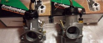
Rice. Carburetor K-30 (K-26): 1 - jet; 2 — spray needle.
Carburetors K-26 and K-30 are completely identical in design and differ only in the size of the main jet.
As can be seen from the figure, the carburetor fuel chamber is cast integrally with the mixing chamber. The float chamber contains a brass float and a shut-off needle. Fuel is supplied to the float chamber from above. Since the point of the needle directly closes the filling hole, there is no need for any special locking mechanism. The float chamber communicates with the mixing chamber through two channels. Fuel is supplied to the mixing chamber through a channel that connects to the well of the mixing chamber.
At the top of the float chamber, above the normal fuel level, there is a hole that connects the float chamber to the top of the well. Gasoline flows into this hole only if the fuel level rises above normal, which occurs when the float is flooded while starting the car, etc. The mixing chamber has a cylindrical throttle valve, closed by a coil spring and opened by cable tension, which is operated by the right rotating handlebar. The mixing chamber is closed on top with a plastic or metal threaded lid. The cover contains a stop tube for adjusting the length of the cable sheath; the stop is locked using a locknut.
The throttle valve has a conical shaped adjusting needle, which fits inside the nozzle and, when the throttle valve moves, increases or decreases the flow area of the nozzle. The adjusting needle can be fixed relative to the throttle valve in four positions. For this purpose, four cutouts are machined on the upper part of the needle, into one of which the locking washer of the adjusting needle is inserted.
The atomizer is screwed into the body of the mixing chamber, and the nozzle is screwed into the lower part of the atomizer.
At the bottom, the mixing chamber is closed with a threaded plug.
The K-30 (K-26) carburetor is attached to the cylinder suction pipe using a clamp that tightens the cut part of the mixing chamber, which is put on the pipe. To protect the carburetor from the transfer of heat from the cylinder, a gasket made of thermal insulating material is laid between the pipe and the part of the mixing chamber placed on it.
Carburetors K-30 and K-26 operate on the principle of mechanical fuel braking. From the float chamber, fuel enters the well and through the nozzle into the atomizer.
When the throttle and mixing chamber are partially open, a vacuum is created above the nozzle, as a result of which the fuel rises up the nozzle and, mixing with air at the outlet of the nozzle, enters the engine. In this case, the fuel is dosed by the throttle adjustment needle, since the flow area between the atomizer body and the throttle needle is less than the cross-section of the nozzle. With further opening of the throttle, the vacuum above the nozzle increases, the flow area of the nozzle increases, and as a result, the flow of fuel also increases. When the throttle is fully raised, the dosing and flow of fuel is carried out by the jet.
Carburetors K-30 and K-26 do not have special devices for adjusting the engine idle speed, and the idle speed is determined by the height of the throttle valve. In order to ensure that the throttle valve does not close completely, i.e., so that the engine does not “stall” when the throttle handle is completely closed, by unscrewing the stop of the cable sheath, the latter is pulled in such a way that the throttle valve cannot be completely closed and is constantly open as much as this is necessary for the engine to operate at low speeds.
The fuel level of the float chamber of the K-30 (K-26) carburetor must be maintained 25 4-1 mm below the upper edge of the float chamber. Float weight 8 +/- 0.5 g. The weight of the assembled carburetor (without air cleaner) does not exceed 350 g.
Rice. Diagram of the K-30 (K-26) carburetor.
Carburetor K-28
The K-28 carburetor is installed on IZH-350 motorcycles. A quencher is placed in the float chamber cover. The float chamber is connected through a channel to the well in which the main jet is installed. Using the low-speed channel, the well communicates with the mixing chamber through two holes, with one hole in the channel coming out behind the throttle valve, and the other in front of it. In addition to the exits to the mixing chamber, the low-speed channel communicates with the atmosphere. The flow area of the last channel is adjusted using a conical screw, and the outlet hole is covered with a small mesh filter.
Rice. Carburetor K-28
The main jet is screwed into the atomizer, which in turn is screwed into the mixing chamber body. The upper part of the well communicates with the atmosphere through a wide channel, which originates at the inlet of the mixing chamber.
The throttle valve of the K-28 carburetor has the usual cylindrical shape for motorcycle carburetors. The damper is lifted by tensioning a cable connected to the rotating handle of the steering wheel; the throttle valve is lowered under the action of a spring located around the cable and its upper end resting on the lid of the mixing chamber, and its lower end on the upper part of the throttle valve.
In addition to the throttle valve, an air damper (air corrector) is installed in the mixing chamber. This valve runs in a slot at the rear of the throttle and is also controlled by a cable and spring. The cable is connected to a lever (shifter) on the steering wheel. By operating the lever you can raise or lower the air damper. Adjusting the length of the sheath of the cables that control the dampers is carried out by screwing in or unscrewing the thrust bushings, which in turn are screwed into the mixing chamber cover.
Rice. Diagram of the K-28 carburetor: 1 - main jet; 2 — spray needle; 3 — screw for adjusting the mixture quality at low speeds.
The K-28 carburetor operates on the principle of mixed fuel regulation. Let's consider the operation of this carburetor at different engine operating modes.
When the throttle valve is closed or slightly open, fuel is supplied through the low speed channel. At the moment of rarefaction, the fuel begins to rise from the well and mix with air, which, as already mentioned, can enter the low-speed channel in two ways: through the hole, which is under atmospheric pressure in the initial stage of opening the throttle valve, and through the hole, which communicates directly with the atmosphere.
From the above it is clear that fuel from the low speed channel enters the mixing chamber mixed with air, i.e. in the form of a ready-made mixture. As the throttle valve opens, the vacuum begins to spread to the low speed channel outlet located behind the throttle valve, from which the emulsion also begins to flow. With further opening of the throttle, since the resistance of the low-speed channels is relatively high, fuel stops flowing from them and begins to leave the atomizer. The flow area of the sprayer is adjusted by a needle. The higher the needle is raised, i.e., the more the throttle valve is open, the wider the nozzle cross-section and the more fuel flows. When the damper rises above its full stroke, the braking effect of the needle stops, and from that moment on, the amount of fuel entering the atomizer is determined only by the flow area of the main jet. To adjust the height of the throttle valve at idle in order to obtain the desired engine speed when the throttle is fully closed, a thrust screw is screwed into the mixing chamber housing, with which the engine operation is regulated to the desired low speed.
The air corrector is designed to enrich the mixture during engine startup and warm-up periods. Under normal conditions, with a normally adjusted carburetor, there is no need to use an air corrector while driving: the carburetor must, without its help, ensure correct operation of the engine in all modes.
transition from carburetor k-28zh (25mm) to k-68i (32mm)
I decided to replace the K-28Zh carburetor with a K-68 carburetor that was lying around in the garage. k-68I PEKAR factory, 2008, almost new.The main reason for the replacement was that the old carburetor was pouring fuel wildly, up to 9 liters per 100 km - this is clearly too much.
The difference between the carbs in the diffuser, on the K-68I the diffuser is 32mm, on the K-28Zh it is 25mm. jets 270 and 280, that is, the difference is insignificant.
Setting up the K-68I for operation on Jupiter is a bit difficult, but it is possible. The mixture turned out to be enriched, but oh well.
So, the feelings.
1. Launch
The engine starts also easily, but since the K-68 only has a starting device, the engine does not work normally when cold. Very rich. On the K-28, it was possible to adjust the quality of the mixture using a corrector, from rich to lean. there is no such thing on the K-68, there are currently 2 modes - startup and operation. In general, you won’t be able to adjust the mixture on the fly.
2. Engine idling
with the K-68 carburetor, the engine runs very smoothly, even when the K-28 was in normal condition - it did not hold speed like that.
3. Engine operation while driving
What is immediately noticeable is that due to the larger diffuser of the K-68I carb, the thrust at the bottom dropped. The smaller the diffuser, the better the low-end traction. 25mm versus 32mm - the difference was noticeable. But I got awesome top and mid-range revs, the motorcycle seemed to have a second wind, which is interesting - the engine almost doesn’t react at all to the intermediate position of the throttle from 1/2 to 3/4 turns, but if you turn the knob all the way - for half a second nothing, and then a soft push and acceleration. And the engine reacts sensitively to slight unscrewing of the throttle. The engine began to turn over and quite well, before I couldn’t even think about 60 km/h in 2nd gear. Acceleration has become much better, but to do this you have to turn the engine. In general, before it was more about traction, now it’s about power. The old carb cut the top a lot and was not very responsive to the throttle. In city conditions, this is rather a plus, it’s still not a truck, previously you had to carry loads in a cradle, but now you rather need a quick start from a traffic light and smooth idle, so as not to rev the gas at intersections.
4. Cost-effective
There’s not much to say here, before it was about 9 liters per 100 km, but right now I haven’t had time to measure it yet. I don't think there will be more. At idle before, when turning off the tap, it could rattle for about 40 seconds, now - for several minutes
Conclusion - a new carb is a new carb, in general I like the behavior of the motorcycle much more now, it has become more interesting and exciting, it’s interesting to ride and play with gas.
Carburetor K-37
Rice. Carburetor K-37
The K-37 carburetor is used on M-72 motorcycles. Since one carburetor is installed for each cylinder of the engine of this motorcycle, then, based on the peculiarities of the arrangement of the cylinders of the M-72 engine, the K-37 carburetors are right and left. Structurally, both carburetors are exactly the same and differ only in the location of the float chamber relative to the mixing chamber. The float chamber is cast integrally with the mixing chamber. Fuel supply is carried out from above.
A quencher is placed in the float chamber cover. The float chamber communicates with the mixing chamber through the window. The space at the bottom of the mixing chamber forms a well in which the main jet is located, screwed into the atomizer. The well communicates with a low speed jet, which is installed slightly above the fuel level in the well. The low speed channel communicates with the atmosphere, and the amount of air entering the channel is regulated using a screw. The low speed channel outlet is located behind the throttle valve. The upper part of the nozzle is surrounded by an annular space, which communicates through an opening with the nozzle and exits into the mixing chamber, concentrically surrounding the mouth of the nozzle.
Rice. Diagram of the K-37 carburetor: 1 - main jet; 2 — low speed jet; 3 — screw for adjusting the mixture quality at low speeds; 4 — spray needle; 5 — air channel of the sprayer; 6 — air channel of the low speed jet.
The K-37 carburetor throttle valve of a conventional cylindrical shape is raised by cable tension from the rotating steering wheel handle, and lowered by spring pressure. The spring rests with one end on the float chamber cover, and the other on the throttle valve.
An adjusting needle is fixed in the throttle valve, which enters the nozzle with its conical end and, when the throttle moves, changes the flow area of the nozzle. The position of the needle relative to the throttle valve may vary. To do this, four holes are made in the upper part of the needle, through one of which a cotter pin is passed, securing the needle to the throttle. In addition, for this cotter pin, two holes are made in the throttle body, one higher than the other. Thus, the range of possible needle adjustments is within eight movements, which gives a total needle movement of 8 mm.
The K-37 carburetor operates on the principle of mechanical and pneumatic fuel braking.
When the throttle valve is closed or covered, fuel is supplied through the low speed jet. At this time, the air passes through a channel communicating directly with the atmosphere and with the inlet of the mixing chamber. As the throttle valve opens, the vacuum spreads to the nozzle and fuel begins to flow through the main jet. At the same time, due to the difference in vacuum between the mouth of the nozzle and the beginning of the air channel, air begins to flow through the latter, which, mixing through the holes in the mouth of the nozzle with the fuel, creates a mixture. The low speed jet, which has a relatively high resistance, gradually ceases to function. With further lifting of the throttle valve, the vacuum at the mouth of the nozzle and at the inlet of the air channel is equalized and the amount of fuel coming from the nozzle is regulated only by the gap between the nozzle and the adjusting needle. This cross section increases with the rise of the throttle valve. When the latter rises above 3/4 of its full stroke, the regulating action of the needle stops and the amount of incoming air is determined only by the flow area of the main jet.
Thus, there are three modes of operation of the K-37 carburetor, not counting idling (the throttle valve is closed), in which fuel flows through the low-speed nozzle, and air through its channel:
- low engine speeds (the damper is slightly raised) - fuel enters through the main jet and is slowed down by air passing through the air channel of the atomizer (pneumatic fuel braking);
- medium engine speed (the throttle valve is raised so much that it does not reach the middle of its stroke or above it) - fuel enters through the main jet; Fuel braking is carried out by the flow area of the nozzle and the cone of the throttle valve adjusting needle;
- high engine speeds (throttle valve is raised above 3/4 of its stroke and until fully open) - fuel enters through the main jet; the amount of incoming fuel is determined only by the flow area of the nozzle.
To obtain the required engine speed at idle with the throttle fully closed, the closing amount of the throttle valve of the K-37 carburetor is adjusted using a thrust screw screwed into the body of the mixing chamber. Using this screw, the engine can be adjusted to any number of low speeds.
How to properly adjust carburetors
In order to adjust carburetors, you need to know this: First of all, this work must be done after adjusting the valve clearances and ignition. Carburetors should not be worn out or different, otherwise it will be very difficult or even impossible to adjust them.
First we adjust the idle speed with the quantity and quality screws. This adjustment DOES NOT AFFECT driving modes! If there are problems while driving, there is no need to turn the screws. The quality screw regulates the ratio of gasoline and air in the mixture, the quantity screw raises the throttle valve, adjusting the idle speed. They need to be turned smoothly and slowly, 1/4 turn or even less, especially on carburetors K-301 and K-302. Now how to find these screws:
On the K-301 and K-302 carburetors, 1 is the quantity screw, 18 is the quality screw.
On the K-63, K-65, K-68, KARTECH carburetor: 28 is the quantity screw, 29 is the quality screw.
1. Loosen the cable so that it plays on the carburetor, set the needles on the carburetors to the middle position. 2. tighten the mixture quality screws all the way and unscrew them 1.5 turns. 3. Start and warm up the engine. 4. turn off the right cylinder by pulling the high-voltage wire from the spark plug. If the ignition is electronic, the wire must be shorted to ground, otherwise it will burn out. 5. On the left cylinder, lower the throttle valve (to the minimum stable operation of the engine) with the mixture quantity screw. If it stalls, start it on two cylinders, then turn off the right one again. 6. Unscrew the mixture quality screw and achieve maximum speed. 7. Reduce engine speed using the mixture quantity screw. 8. Repeat steps 5-7 until the valve is lowered to the very limit, usually 2-3 times.
9. Now turn on the right cylinder, turn off the left one and adjust the right carburetor (steps 5-8). 10. By alternately pulling the right and left high-voltage switches off the spark plug, you need to achieve the same audible speed from both boilers. 11. Connect both and by simultaneously tightening the mixture screws the same number of turns, we achieve the minimum stable idle speed. The motor should produce a uniform “thump-thump-thump” sound and should not jerk.
Well, we have adjusted the idle speed, now we will adjust the cables so that they raise the dampers at the same time and so that the cylinders work synchronously at operating modes.
12. Place the motorcycle on the center stand. 13. Start the engine and pull off the high-voltage wire from the right boiler. 14. Engage 4th gear and accelerate the engine according to the speedometer to 55 km/h. 15. Fix the throttle (there is a small screw on it for this purpose). 17. We attach the right high-voltage voltage, pull off the left one. 18. We adjust the RPM with the cable sheath screw so that the speedometer shows the same 55 km/h 19. We turn off the engine and lock the cable sheath screws.
Now our task is to adjust the main dosing system. I hope your carburetor needles are straight and your throttle bodies are not worn out!
20. We drive at a speed of 70 for 10-15 minutes. 21. look at the color of the candles. Brown/black - lower the needles one notch. White - raise one notch. Should be brick color. If it is a K-63 carburetor and the needles are threaded, then they need to be rotated 2-3 turns.
22. Repeat points 13-19
That's it, the adjustment is complete! If the motor overheats during this process, you need to let it cool down. Good luck on the roads!
Carburetor K-40
Rice. Carburetor K-40.
The K-40 carburetor is installed on PZh-350 motorcycles. This carburetor has a float chamber with fuel supply from the top. The fuel level in the float chamber is 24+1.5 mm below the upper edge of the chamber. The float chamber is connected to the mixing chamber by a channel.
Fuel, having entered the mixing chamber, can go to the main jet and the low speed jet.
Rice. K-40 carburetor diagram: 1 - main jet; 2 — low speed jet; 3 — screw for adjusting the mixture quality at low speeds; 4 — spray needle.
After passing through the low speed jet, the fuel is mixed with air. The air passes through a channel starting at the carburetor inlet. Next, the mixture in the form of an emulsion can enter the mixing chamber through two channels; one of these channels exits in front of the throttle valve, and the other behind it. The amount of air is adjusted using a needle screw.
The fuel passing through the main jet fills the well, which communicates with the mixing chamber through the atomizer. The atomizer includes an adjusting throttle needle, which changes the flow area of the atomizer.
An air nozzle is located concentrically around the mouth of the atomizer. Air enters the nozzle from the second air channel, which originates at the carburetor inlet. The nozzle mouth has an oblique cut, the high part of which is above the nozzle outlet and is located in the direction of the carburetor inlet; The lower part of the dream is at the height of the sprayer in the direction of the engine intake port.
The throttle valve of the K-40 carburetor has the usual cylindrical shape for motorcycle carburetors, and the lower part of the valve is stepped.
In addition to the throttle valve, the K-40 carburetor has an air damper (air corrector). This valve looks like a bolt that fits into a corresponding groove cut into the throttle valve. An adjusting needle is also attached here, which is held in the valve by a cotter pin and its conical end enters the inside of the atomizer, changing its cross-section when the throttle valve moves.
The throttle and air valves are controlled by cables and springs. The gas supply cable is tensioned by rotating the handle on the steering wheel, and the choke cable is tensioned by moving the lever (shifter). The length of the sheath of each cable is adjusted by stop tubes screwed into the cover of the carburetor mixing chamber.
Let's consider the action of the K-40 carburetor.
The engine is started with the throttle valve almost completely closed. The fuel-rich emulsion is sucked into the engine through the low-speed channel opening, which exits into the mixing chamber behind the throttle valve. As the throttle valve opens, the vacuum spreads to the second outlet of the low speed channel, and for some time the mixture flows from both holes. When the damper is further opened, the vacuum spreads to the atomizer, fuel flows from it, and air flows from the concentrically located hole of the air nozzle. Due to the stepped cut of the lower part of the throttle valve, mixture formation is ensured. Due to the relatively high resistance of the low-speed channel, the mixture from its holes stops flowing. Increasing the throttle opening gradually stops the flow of air through the nozzle, and the fuel leaving the nozzle is mixed with air entering directly through the carburetor inlet. The amount of fuel is dosed by the size of the gap between the cone of the throttle valve adjustment needle and the inner diameter of the nozzle. When the damper is raised more than 3/4, the action of the adjusting needle is exceeded and the amount of fuel coming from the atomizer is determined directly by the cross-section of the main jet of the carburetor. To adjust the throttle lift height at idle in order to obtain the desired low engine speed when the throttle is completely closed, the K-40 carburetor is equipped with a thrust screw, the design of which is similar to that of the thrust screw of the K-28 and K-37 carburetors.
Carburetor K-36
Has 2 adjusting screws: quality and quantity. The main difference from other carburetors: when tightening the screw 18
the mixture becomes leaner, and when unscrewed, it becomes richer. All modifications are indicated by a letter index. The diffuser diameter is marked on the body and nozzle.
The K-36 carburetor is adjusted as follows: start and warm up the engine. Set the fuel adjuster lever to the “away” position. By turning out or screwing in screw 1, set the minimum possible engine speed. Screw screw 2 all the way and, gradually unscrewing it, achieve clear and stable operation of the engine. Using setscrew 1, lower or raise the throttle to the minimum stable idle speed. The quality of the mixture in operating modes is adjusted by moving the metering needle in the throttle valve to one of the four annular grooves, while raising the metering needle ensures enrichment of the working mixture, lowering ensures depletion.
| Main characteristics of carburetors of the K-36 family | |||||
| Carburetor model | K-36B | K-36D | K-36 Zh | K-36 I | K-36 F |
| Mixing chamber diameter, mm | 28 | 28 | 26 | 28 | 28 |
| Diffuser diameter, mm | 25 | 27 | 24 | 27 | 27 |
| Fuel level in the float chamber, mm | 21 | 21 | 21 | 21 | 21 |
| Main jet flow capacity, cm3/min | 210 | 280 | 275 | 260 | 190 |
| Spray diameter, mm | 2,6 | 2,6 | 2,6 | 2,65 | 2,6 |
