How to check
There are two options for checking the functionality of the sensor:
- With the need to remove;
- With thermometer;
- Without thermometer;
- Right on the spot, without taking off.
But first you need to make sure that the sensor is receiving power. Remove the chip from the DTOZH and measure the DC voltage with a multimeter. It should be about 5 V. If it is approximately within these limits, we check further.
Without removing the sensor, you can check its performance in the following way. We disconnect the chip. We measure the resistance between the sensor contacts. When the engine is cold, the resistance will be higher, and when the engine is hot, it will be lower. For example, let's give a data table for the VAZ-2110 car. For other cars that use similar sensors, the numbers will be approximately the same.
| Water temperature, °C | Resistance value, Ohm | Water temperature, °C | Resistance value, Ohm |
| +5 | 7280 | +45 | 1188 |
| +10 | 5670 | +50 | 973 |
| +15 | 4450 | +60 | 667 |
| +20 | 3520 | +70 | 467 |
| +25 | 2796 | +80 | 332 |
| +30 | 2238 | +90 | 241 |
| +40 | 1459 | +100 | 177 |
To remove the sensor, a simple wrench will be enough. After removing it, you need to take several measurements with water of different temperatures. We heated the water and poured it into a glass. We also lower the thermometer and sensor there. More precisely, its sensitive element. We connect the multimeter probes to the electrical contacts. We measure the water temperature and sensor resistance. We record the data. Then we heat the water a little more and repeat all the steps. And so several times, for example, record the indicators at a temperature of +15 °C, +20 °C, +25 °C and so on. And then just compare these numbers with the numbers in the table above. But it’s better with technical documentation.
How to test the sensor for damage without using a thermometer? We do the same thing, but bring the water to a boil. And, referring to the table above - the sensor resistance should be
177 Ohm. Of course, errors are possible here, since while you are getting ready to take measurements, the water will be a couple of degrees colder, which means the resistance will be a little less. This is also worth considering.
If the sensor gives you very different numbers, urgently replace it.
How to clean the throttle valve
There are a number of special products designed to clean the surface of the throttle valve. Some craftsmen use WD-40, acetone, solvents and other similar compounds for this. In principle, they can be used, but the risk of damaging something inside the engine increases. Today, car dealerships sell a large number of special products for carrying out this procedure. All of them are relatively inexpensive. Therefore, taking into account the fact that the throttle valve does not need to be cleaned so often, any car owner is able to purchase such a product.
| Name of the product | Description | average price | Notes |
| LIQUI MOLY DrosselKlappen-Reiniger (LM-5111) | The best throttle body cleaner available today. Cleans dirt and oil deposits efficiently. | 520 rub. | Aerosol, volume 400 ml in a cylinder. |
| Mannol Carburetor Cleaner | It cleans oil and dirt well from the valve. It costs less than ABRO, and the cylinder has a larger volume. | 115 rub. | Aerosol, volume 400 ml in a cylinder. |
| ABRO Carb&Choke Cleaner (CC-220) | High quality cleaner. Popular with car owners in our country. | 200 rub. | Aerosol, volume 220 ml in a cylinder. |
The cost is indicated as of prices for summer 2021 for Moscow and the region
How to remove and check the sensor?
Throttle position sensor VAZ 2114 price
Access from above to the Priora DD is difficult due to the intake module located above it. The easiest way to get to the sensor is from below, first removing the engine protection or at least unscrewing and folding its front part. When working from above, you will have to do everything by touch. In any case, before starting work, it is necessary to disconnect the ground wire attached to the “negative” terminal from the battery.
To remove the crankcase protection, you need to:
- unscrew 5 nuts with a 10mm head;
- unscrew the 2 19 nuts installed on the back of the shield;
- remove protection.
- by pressing the metal latch of the DD connector, disconnect the block of wires going to the controller;
- using a 13mm wrench, loosen the bolt securing the sensor;
- Unscrew the bolt and remove it from the threaded hole, removing the sensor.
Photo of dismantling the knock sensor
- We connect a multimeter to the DD terminals. We set the device to voltmeter mode, choosing a measurement limit of up to 200 mV.
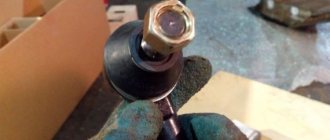
- We take a metal object - pliers or a bolt - and lightly tap it on the DD.
When you tap on a working sensor, the voltmeter will show voltage surges. A faulty DD will not react in any way. A more accurate diagnosis of a removed sensor can only be done using a special stand.
In the photo - diagnostics of the knock sensor
Installation of a new DD is carried out in the reverse order of dismantling. Experts recommend installing a similar Bosch instead of the “native” one. Before going to the store for a new sensor, you should write down the markings of the removed sensor. The bolt securing it to 13 must be tightened with a slight force - 10.4–24.2 Nm (1.1–2.5 kgf). Tightening too tightly will affect the operation of the sensor.
Checking the position sensor
Before you check the throttle position sensor on any car, you need to estimate its average mileage. As a rule, contact sensors die already at 70-80 thousand km, while non-contact sensors last much longer. Therefore, if the sensor is old, it is better to immediately put it on the shelf and replace it with a new one. This pleasure is not so expensive, since back in 2015 you can buy a sensor for a Priora or dozens for 300 rubles. It will be either a Moscow or Kursk device. A sensor with the inscription “GM Made in Russia” is already offered for 800-900 rubles. Frankly speaking, there is not much difference, judging by the reviews.
Removing and cleaning the throttle assembly
Throttle position sensor
Many owners of carburetor cars are familiar with such a procedure as flushing the carburetor. But the owners of injection cars, including Kalina, think that if the car has fuel injection, then there is no need to clean or rinse anything. In fact, the Kalina injector throttle assembly also needs regular cleaning. Of course, you shouldn’t do this constantly every 10,000 km, but I would recommend doing this procedure once every 50 thousand km.
Before removing the throttle body from the vehicle, first familiarize yourself with the accessories:
List of necessary tools for removing the assembly
- Flathead and Phillips screwdrivers
- Head for 13
- Extension cord short
- Ratchet or crank
- Pliers (in some cases)
Before starting repairs, disconnect the battery by removing the negative terminal, since you will then have to disconnect the sensor plugs, and the turned on power will be of no use.
Instructions for removing the throttle assembly from Kalina 1.6 8 valves
The first step is to disconnect the inlet pipe that runs from the air filter to the unit itself. Loosen the clamp as shown in the photo below:
You also need to loosen the thin hose that extends from the inlet. It is better to do this from the side of the valve cover:
Then we disconnect the thick pipe and this thin hose and move them to the side so that they do not interfere with us in the future:
Then you need to unscrew all the hose clamps that are connected to the throttle assembly. Three of them are at the top:
And the fourth is at the bottom of the throttle; the photo below clearly shows its location:
If you have problems removing the hoses, you can use pliers. Carefully grasp the seat of the hose and twist it along the tube. Like this, as shown in the picture:
Now we disconnect the plugs from the sensors, which are located on the inner side of the unit. The result should look like this:
There is very little left: unscrew the two nuts securing the unit to the manifold. The most convenient way to do this is with a ratchet with an extension - for the lower nut, and for the upper one you can do without it.
And remove this entire structure from the studs:
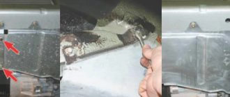
All that remains is to free yourself from the throttle cable. To do this, take a flat-head screwdriver and pry up the metal bracket on one side, approximately as shown in the photo below:
Then we pry this latch with our finger and take it out:
Then we take the throttle cable with our hand and lower it to the very bottom so that it is opposite the removal hole:
And on the reverse side, pressing a little on the holder, move the cable to the side and calmly remove it:
That's all ready - now the throttle assembly can be removed completely, because there are no more obstacles to this:
Cleaning or flushing the Kalina throttle
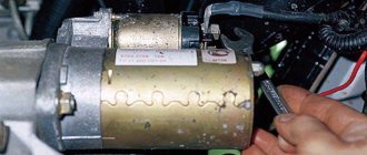
After my mileage, just under 50,000 km, the condition inside was quite normal, I did not find any strong deposits or soot. There was only a little dark coating, something like soot on the walls:
I didn’t wash it, but just took a dry, clean rag and thoroughly wiped everything inside to a factory shine. If you decide to do a full flush, first unscrew the sensors from the assembly. Black plaque also accumulates in their seats, which will need to be removed.
It is convenient to clean the internal cavity with an old toothbrush. After carrying out all the procedures, we wipe everything dry with a napkin or a clean rag and air it inside so that not a single grain of sand or dust remains.
We carry out the installation in the reverse order, connecting all the wires and hoses in place. The result of the work done showed that it was not in vain that I tried and experimented with my Kalina. Now, when starting the engine, the engine began to “shoot” as it should be on a new car.
ladakalinablog.ru
TPS functions
The throttle valve is an element included in the engine intake system. Let us immediately note that the design of the throttle assembly is the same for both the 8-valve engine and the 16-valve engine. The meaning of its activity is to regulate the air entering the engine. The throttle position sensor transmits information to the manifold about the current state of the bypass valve. There are two types of sensors - magnetic (non-contact) and film. Its design is similar to an air valve, in which, when open, the system pressure and atmospheric pressure are identical; when closed, the pressure becomes close to vacuum.
The sensor includes a variable and constant resistor with a resistance of up to 8 ohms. The output voltage changes depending on how the damper is positioned. The system has control, thanks to which the fuel supply is regulated.
When the sensor is faulty and the readings are distorted, the fuel supply is disrupted, engine operation is disrupted, and in some cases the engine fails.
In addition, a working sensor will protect the gearbox and ignition switch.
How to clean the throttle valve on a Priora yourself
Throttle position sensor lada kalina
To carry out such a procedure, it is not at all necessary to go to the service. Everything can be done independently. Cleaning the throttle valve on a Priora is not a complicated procedure, and it will take a little time to do everything - about half an hour. It should be warned that before starting work directly, you need to let the engine cool down - this is a matter of your own safety.
In order to clean the Priora throttle valve, you need a minimum set:
- set of wrenches;
- screwdrivers - flat and Phillips;
- cleaning agent - it’s difficult to name a specific one, their choice today is quite wide.
However, first of all, we need to get to this node. We put the car in neutral, not forgetting to apply the parking brake. Next, remove the plastic engine cover and the cap from the expansion tank. After this, loosen the clamps holding the air pipe and carefully remove it. While performing these operations, you can at the same time inspect the engine and engine compartment for possible leaks.
Next, remove the damper heating pipes, having first loosened the clamps. To prevent dirt from getting inside, you can plug the pipes with a rag. After this, it is advisable to disconnect the hose used to ventilate the fuel tank. Now all that remains is to unscrew the bolt, remove the throttle cable and remove the damper itself.
The first stage of work is completed, and you can proceed directly to cleaning. Using a pre-purchased product, thoroughly wash the damper and all its channels. In the latter case, you can use a knitting needle with a rag wrapped around its end. Remove and wash the idle speed sensor. To do this, you will need to unscrew 2 bolts. At the same time, we carry out visual diagnostics for various kinds of visible defects. The work is considered complete if no traces of dirt are visible on a clean rag that you run through the channels.
Now all we have to do is replace the gasket and put the damper in place. All work here is carried out in reverse order. I would like to warn you that everything needs to be done very carefully so as not to accidentally drop anything inside the collector. As you can see, there is really nothing complicated in this procedure. Everything can be done on your own with minimal effort and time.
After the damper is put in place, you should check how effective this procedure was
In particular, pay attention to starting the engine - it should start, as they say, with half a turn. There should not be any extraneous sounds. Next, try the car on the move, switching from high to low gear, or even better, to “neutral”
A normal decrease in speed will be the main sign that everything is done correctly
Next, try the car on the move, switching from high to low gear, or even better, to “neutral”. A normal decrease in speed will be the main sign that everything is done correctly.
Throttle learning idle
Throttle Position Sensor Symptoms of Malfunction
After flushing the unit or reflashing the ECU, the throttle valve should be trained to idle. To do this, fulfill the following conditions:
- check the voltage on the battery with the engine off, it should be at least 12.9 V;
- the coolant temperature should be in the range from 70 to 100 degrees;
- the steering wheel must be in a neutral position;
- The gearbox oil must be warmed up;
- all electrical consumers are turned off;
- automatic transmission handle in position P.
Failure to comply with the above requirements will lead to incorrect operation of the engine, so they must be followed. After warming up the engine, you must:
- turn off the ignition for 10 seconds;
- make sure that the accelerator pedal is in the up position;
- turn the key to the ON position for 3 seconds (do not start the engine);
- Press the gas pedal all the way 5 times within 5 seconds and release it for the last time;
- after 7 seconds, press the gas pedal all the way and wait until the “CHESK ENGINE” display lights up continuously;
- After pausing for 3 seconds, release the gas pedal.
Try to start the car, the attempt can be repeated several times. During stable operation, rev the throttle several times and the idle speed should return to the acceptable range.
The procedure for learning the throttle using a PC and car programs has its own specifics, depending on the brand of car, etc. Therefore, it makes no sense to describe the entire process in detail. But first you need to install special software on your PC, for example, VAG-COM for a VAG car group (or other) and drivers. The following is the standard connection order for all:
- turning on the ignition;
- connecting the PC to the car diagnostic connector with an information wire;
- launching software on a PC;
- conducting a test;
- receiving information about readiness for further work - the inscription: “The adapter is ready for work.”
Following a special algorithm, you will be able to coordinate the remote control and the ECU in the “throttle fully open/fully closed” modes for cars with both an electronic and mechanical gas pedal. In this case, the throttle valve training is carried out when the car is warm and the above requirements are met.
Features of checking contact and non-contact TPS on Priora: pinout
If the corresponding signs of a malfunction of the TPS on the Priora appear, it would not hurt to check the product to make sure that the sensor has actually failed and that the wire has not been damaged or the contacts in the power supply have oxidized. To do this, you will need to know the TPS pinout, which is presented in the diagram below.
The easiest way to check is to use a multimeter. The detailed process for checking the Priora TPS is described below:
- Checking the serviceability of the supply wires. Disconnect the power supply from the sensor. Connect the multimeter probes to pins A and B, then turn on the ignition and check the voltage. The supply voltage should be 4.8-5.2V. If the value differs from the specified value (usually it is lower), then you should look for the cause in a wire that has a short to ground.
- Next, we proceed to check the contact sensor. The best way to check it is to measure the resistance between contacts A and C, that is, the signal and positive contacts. It is recommended to perform the test on a removed sensor. We connect the probes to the corresponding terminals and measure the resistance in kOhms. It should be in the range from 1 to 3 kOhm. When changing the position of the slider, the resistance should increase, and very smoothly without sudden jumps. If a different picture is observed, then the TPS needs to be replaced.
- Another test method (suitable for both contact and non-contact devices), which does not require removing the sensor, is to measure the voltage at the signal contact. However, it is recommended to implement it in exceptional cases, since it involves violating the integrity of the contacts of the sensor chip. It is carried out as follows: using pins, you need to attach the probes of the multimeter to the back side of the chip. You need to connect to terminals B and C, that is, signal and ground. After connecting, you need to turn on the ignition and, without starting the engine, change the position of the damper. If the voltage smoothly increases to 5V when the damper is opened to maximum, it means the part is working properly. If sudden changes (jumps) occur in the contact-type TPS, the product must be replaced. If the non-contact TPS is faulty, then its voltage will not change or will change, but in a low range.
Below is a video that shows in detail the process of checking the mechanical TPS.
Having confirmed that the throttle position sensor on the Priora is faulty, it should be replaced. Do not attempt to disassemble or repair it, as it is not repairable.
This is interesting! You can check the health of the sensor using a Bluetooth scanner connected to the OBD2 connector, as well as a special application on your smartphone.
If the BC displays a low signal error from the sensor, you need to check the power wires, since most likely the insulation has been damaged. If the signal level is high, then the fault is probably in the sensor itself.
Operating principle of the sensor
To make it easier to understand the scheme of its operation, let’s imagine it this way, as a variable resistor mounted on the throttle valve axis with a moving part. Voltage is constantly supplied to the sensor, and depending on the position of the damper, the position of the sensor changes, and, consequently, its resistance also changes. It sends an impulse to the electronic control unit, which in turn, based on sensor readings, builds a recipe for supplying fuel to the combustion chamber - the amount of fuel, the amount of air, the ignition timing, the opening or closing of the exhaust gas recirculation valve. In short, based on the readings of this small sensor, the entire engine control plan for the next few seconds is prepared.
Regardless of the type of sensor, the voltage limit for its operation ranges from 0.5-5 volts, depending on the engine model. Injection cars VAZ 2110, 2112, Priora, Kalina use a working range from 0.7 to 4 volts. That is, when the throttle valve is completely closed, the pulse at the sensor output is 0.7 volts, and when it is fully open, it is 4 volts. Other cars may have different voltage characteristics, but the essence of the sensor’s operation does not change.
What are the effects of TPS malfunctions?
- On the idle speed parameters. Injectors do not have a unified system for this stroke in the form in which we are accustomed to seeing it in carburetor engines. All parameters of this mode are calculated only from TPS readings. Unstable speed, interrupted engine operation.
- Increased fuel consumption. The device sends a dubious signal, which is perceived by the ECU as a closed damper (although in reality it is open). Parameters are included that imply an increase in the proportion of fuel in the mixture. It turns out that the car operates as usual, with a stable shaft rotation speed, and consumes much more gasoline.
- As you pick up speed, you feel dips and the car jerks noticeably.
- When the position of the accelerator pedal remains unchanged, the car jerks, and when the pedal is suddenly released, the engine completely stalls.
- The car does not pull, you feel a loss of power.
The Check Engine button turns on, indicating that the error has been detected.
Basic damper malfunctions
When contacting a service station, breakdowns of the throttle valve are observed. I’ll tell you in detail about each of them.
Position sensor
The most common failure occurs in the throttle position sensor. This mechanism breaks down, which leads to disruption of the power unit:
- The car starts with difficulty or does not respond at all to turning the key in the ignition system.
- When driving, there are jerks or dips in the operation of the motor.
- Fuel consumption increases.
- Traction and dynamic performance deteriorate.
- Unstable idling: the engine runs at high speeds or may stall.
- The “Check Engine” indicator on the instrument panel periodically lights up.
Broken position sensor
I note that all these signs may indicate not only a valve failure. Here it is necessary to carry out diagnostics of all systems at the service station.
Clogged bypass channels
The malfunction is also caused by atmospheric air passing through the damper when the diesel engine is running. While driving, fine dust particles pass through the air filter. Even the oil mixture passed through the system can lead to contamination of the bypass channels. The particles mix with the liquid to form a complex coating. With such a breakdown, problems will only appear when the engine is idling.
Classic cleaning of the throttle valve helps eliminate the main problems. You will have to work hard if there are more serious faults. For a visual assessment, the worker will have to remove all rubber seals and other parts of the module. If the problem occurs due to a mechanical or electronic control module, it can be resolved with additional tuning.
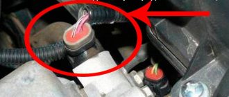
Air leak
In this case, air passes through the throttle block or through the resulting hole in the intake manifold. More oxygen enters the engine than needed, which leads to an increase in speed. Air also bypasses the filters, which leads to rapid contamination of the damper.
The place where air is leaking from inside the damper is marked in red.
If the tightness of the connection between the throttle valve and the intake manifold is broken or the valve does not close completely due to play, this can be eliminated by replacing and cleaning the device. If air penetrates through other places, then you need to check the car at a service station.
Damper adaptation failure
Adaptation is the adjustment of the electronic control unit, which “sees” the position of the accelerator pedal and the position of the throttle valve. A malfunction in adaptation appears when the car battery is disconnected, the engine control unit is reconfigured, the throttle is removed for cleaning, and the engine does not operate correctly at idle. It is better to entrust the adaptation to the masters at the service station; it is inexpensive.
The procedure for replacing TPS on a Priora yourself
Before starting this repair, you must ensure that there is no power to the sensor harness connector. It is best to completely turn off the power to the car by disconnecting the “-” terminal from the battery.
Next, you need to disconnect the plug from the TPS, as is clearly shown in the photo below, after slightly pressing the latch upward.
Now, using a Phillips screwdriver, unscrew the two screws securing the sensor to the throttle assembly. The picture below demonstrates everything clearly.
Next, take out the TPS without putting much effort.
Please note that at the installation site of this sensor there is a special foam ring (gasket), which must be intact and undamaged. When installing a new sensor, check this again
Replacing the TPS is carried out in the reverse order, and difficulties during repairs are unlikely to arise. Before buying a new one, you should rewrite the part code in order to buy the same one.
Photo report on repairs
It is advisable, before any repairs related to the electrical equipment of the car, to disconnect the battery, for which it is enough to remove the negative terminal.
After this, slightly bending the latch of the plug lock, disconnect it from the throttle position sensor:
Then unscrew the two screws that secure the sensor itself to the throttle. Everything is clearly shown in the photo below:
And we can easily remove it after both screws are unscrewed:
The price of a new TPS for Priora ranges from 300 to 600 rubles, depending on the manufacturer. It is advisable to install one that matches the catalog number on the old factory sensor.
When installing, pay attention to the foam ring, which is clearly visible in the photo above - it should be without damage. We put everything in place and connect the wires that were removed.
The injection engine control system consists of a mass of interconnected sensors and detectors. Each of them regularly transmits data to the electronic control unit, and it already makes a decision on how much fuel to supply to the combustion chambers, how to adjust the ignition timing at a specific moment, what gear to engage in the automatic transmission and how to more rationally distribute torque among the axles and wheels if the car is all-wheel drive. We have gone far because today we are interested in one tiny sensor, without which the operation of a gasoline injection engine would be impossible. This is the throttle position sensor.
Content:
How to Determine a Malfunctioning Throttle Sensor
Checking the TPS itself is simple, and all you need is an electronic multimeter capable of measuring DC voltage. So, to check the TPS malfunction, you need to follow the algorithm below:
- Turn on the car's ignition.
- Disconnect the chip from the sensor contacts and use a multimeter to make sure that the sensor is receiving power. If there is power, continue checking. Otherwise, it is necessary to “ring” the supply wires in order to find the break point or another reason why the voltage to the sensor is not suitable.
- Set the negative probe of the multimeter to ground, and the positive probe to the output contact of the sensor, from which information goes to the electronic control unit.
- When the throttle is closed (corresponds to the accelerator pedal being fully depressed), the voltage at the sensor output contact should not exceed 0.7 Volts. If you open the throttle completely (fully depress the accelerator pedal), then the corresponding value should be at least 4 Volts.
- Next, you need to manually open the damper (rotate the sector) and at the same time monitor the multimeter readings. They should rise smoothly. If the corresponding value rises abruptly, this indicates that there are worn spots in the resistive tracks, and such a sensor must be replaced with a new one.
Owners of domestic VAZs are often faced with the problem of TPS malfunction due to the poor quality of the wires (in particular, their insulation) with which these cars are standardly equipped from the factory. Therefore, it is recommended to replace them with higher quality ones, for example, produced by PES/SKK CJSC.
And, of course, you need to check it using a diagnostic tool like the ELM327 or its equivalent. The scanner will accurately indicate the error number, and will also determine whether the car still has problems, possibly in other systems. The most common error associated with the throttle position sensor is code P0120 and stands for “Throttle position/pedal position sensor/switch “A” circuit malfunction.” Another possible error p2135 is called “Mismatch of readings from sensors No. 1 and No. 2 of the throttle position.” After replacing the sensor with a new one, it is necessary to erase the error information from the ECU memory programmatically, or simply remove the negative terminal from the battery for a few seconds. However, it is preferable to use the program.
Conclusion
A malfunctioning throttle position sensor is not a critical failure, but it needs to be diagnosed and corrected as quickly as possible. Otherwise, the engine will operate under significant loads, which will lead to a reduction in its overall service life. Most often, the TPS fails simply due to simple wear and tear and cannot be restored. Therefore, you just need to replace it with a new one.
All modern cars have many electrical and electronic devices in their design. With their help, control and automatic adjustment of the functioning parameters of various components, assemblies and systems is carried out. They can be very complex and expensive, such as an electronic engine control unit (ECU), or very simple. It is noteworthy that many “little things”, the cost of which is very small, play a very important practical role in practice. For example, if signs of a malfunction of the throttle position sensor are detected, then if they are left unattended, a quick and very expensive repair of the power unit is practically guaranteed.
Read also: Mitsubishi Pinin reviews from video owners
How to check the throttle
Checking the throttle is a simple process. It is enough to have a multimeter or just a voltmeter. Adjustment can take place in your garage. To do this, the corrugated tube responsible for the air supply is disconnected, thoroughly washed with alcohol and wiped with a soft cloth. The same procedure is done with the intake manifold and the damper itself.
Inspect everything carefully. If there is no mechanical damage, the sensor is adjusted. Use a wrench to loosen the screws. The damper rises and drops sharply until it stops; If you don't hear the impact, you need to repeat it again. The screws are loosened until the product finishes “biting.” And only after that the fasteners are fixed with nuts. Then the TPS bolts are unscrewed and the housing is rotated, the sensor is set so that the voltage changes only when the damper is opened. Everything returns to its place, the bolts are tightened, the adjustment is complete.
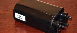
Detonation device on Priora
The knock sensor on the Priora is made in the shape of a circle, it has a hole for connecting wires. Inside it, in a special place, there are certain threads that, when detonation occurs, begin to emit impulses. The threads are made of a thin and rather soft alloy, and even though they are protected by a certain substance, it is under no circumstances recommended to throw the sensor forcefully onto the floor.
Detonation device on Priora
Where is
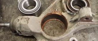
To improve the sensitivity of the knock sensor, it was installed on the Priora engine block. It is attached to a special ledge, as well as a platform, which is located near the second cylinder. This is where the noise from the detonation process is strongest. This place is located on the radiator side, just below the engine itself.
If the Priora is equipped with such technologies, in particular as power steering, air conditioning and many others, then access to them will be a little complicated, but still possible. Simply put, it is accessible from the front bumper of the car.
knock sensor location
Symptoms of a problem
The main malfunctions in the car's knock control system are:
- The device has failed.
- The wire to it broke.
- The device connector is broken.
In all these cases, eliminating all these troubles is an easy task. The main thing is to be able to identify them correctly. In any case, when working with a car with an ECM, diagnosing problems is a rather complex and important area of repair. Fixing the first two problems will require having the following kit on hand:
- Multimeter tester.
- Indicator light.
- Wires.
- Insulating tape.
- Wire cutters or knives.
Then connect the multimeter to the 2 holes of the connector and turn on the ignition. If everything is fine with the circuit, the tester will indicate a voltage of up to 5 Volts. And if nothing happened to the indicators, then the circuit may have broken and needs to be found. You need to disconnect the connector from the ECU and examine both circuits. Find the break and fix it using wires and electrical tape. If the tester shows a working circuit, then the problem is with the sensor.
Knock sensor error
If a network break occurs, this error appears under code 0325. In many cases, the cause of the error is oxidized contacts. But the problem may also not be in the sensor or even in the wiring: so check the timing belt, maybe it has slipped a couple of teeth - check the marks.
Checking the performance of the TPS
The throttle sensor is usually checked with a multimeter in dial mode. They simulate the operation of the valve, then monitor voltage surges on the device scale in sound control mode. If wheezing is heard, the potentiometer definitely needs to be replaced.
Checking the sensor operation with a multimeter
Read more about how inspections are done at car services:
- activate the car's ignition system;
- disconnect the chip from the TPS contacts, connect it to the tester and make sure that current is flowing - if there is no voltage, call all the wiring and find the break point;
- then connect the throttle sensor to the multimeter, connecting one terminal to ground and the other to the main contact of the control unit;
- take the current value with the shutter closed (the gas pedal is not activated) - it should show no higher than 0.7 volts;
- calculate the current when the gas pedal is depressed (the throttle is open) - the indicator is at least 4 volts;
- monitor the readings on the scale, while simultaneously rotating the sector of the device - the increase in current must occur as smoothly as possible, otherwise the tracks will be worn out.
Next, the test is carried out using special equipment through the built-in OBD II system.
ODB II System Diagnostic Tester
Computer diagnostics makes it possible to obtain error codes, after studying which specialists judge the specific causes of the malfunction.
Only after this is a new throttle sensor installed, since without analyzing the complete picture of the unit’s operation, it is risky to do anything.
Here, for example, is some error data with decoding: p0120 - malfunction of the throttle position sensor circuit and p2135 - discrepancy in TPS readings. Also, problems with the potentiometer are indicated by errors under the numbers: p0122, p0123, p0220, p0222, p0223. As for wiring damage, this usually occurs due to poor quality materials. This applies in particular to isolation. After installing a new regulator, the error information is necessarily erased from the memory of the control unit. Usually, to do this, it is enough to disconnect the battery, wait about 15 minutes, then put the negative terminal in place.
Specialists are able to identify malfunctions of the throttle sensor also by the operation of the accelerator pedal. If during acceleration you feel dips and the car jerks strongly. Or the engine vibrates, but the gas is released.
Throttle assembly Lada Priora VAZ 2170, 2171, 2172
| Signs of a throttle valve that is not fully closing may include increased idle speed and increased fuel consumption, and if the throttle valve is not fully opening, the engine will not develop full power. |
| If these malfunctions occur, first try adjusting the throttle valve drive or replace the cable (see “Adjusting the throttle cable”). If this does not lead to a positive result, replace the throttle assembly. |
| You will need: a socket wrench (head) “13”, a screwdriver with a Phillips blade. |
Attention: Do not remove screws 2 securing the throttle valve. If they are then poorly tightened and tightened, the loosened screw can get into the engine cylinder and damage it. The throttle valve position is adjusted at the factory, so it is not recommended to touch the throttle valve adjusting screw 1
The throttle valve position is adjusted at the factory, so it is not recommended to touch the throttle valve adjusting screw 1.
| 1. Drain the engine cooling system (see “Replacing Coolant”). |
| If you're skilled enough, you don't have to drain the coolant. With the engine cool, release excess pressure in the engine cooling system by unscrewing and then tightening the expansion tank cap. Prepare plugs of suitable size that you can use to plug the hoses immediately after disconnecting them from the throttle assembly. The loss of coolant with this method will be insignificant. |
| 2. Disconnect the wire from the negative terminal of the battery. |
| 3. Open the hood and remove the decorative engine cover (see “Engine Cover”). |
| 4. Having released the clamps, disconnect the wiring harness connectors from the throttle position sensor... |
| 6. Disconnect the air supply hose from the throttle body (see “Cleaning the crankcase ventilation”). |
| 7. Loosen the clamp of the first throttle body heating hose... |
| 9. Loosen the clamp of the second throttle body heating hose... |
| 11. Loosen the fastening clamp... |
| 13. Loosen the clamp securing the adsorber purge hose... |
| 15. Disconnect the throttle drive cable from the throttle assembly sector (see “Adjusting the throttle cable”). |
| 16. Unscrew the two nuts securing the throttle assembly... |
| 18. If, when replacing the throttle assembly, the idle air control and throttle position sensor are not installed on the new assembly, replace them with the old assembly. |
| To do this, unscrew two screws securing them. |
| Replace the damaged foam ring located under the throttle position sensor. |
| 19. Clean the dirty throttle assembly with carburetor cleaning fluid, after first removing the sensor and regulator from it. Also clean dirty regulator and sensor (do not use solvents for cleaning). |
| 20. Install the throttle assembly and all removed parts in the reverse order of removal. |
| 21. Adjust the throttle actuator (see “Adjusting the throttle cable”). |
Engine Comparison of engines 21126 and 21124 Engine malfunctions Compression in cylinders Engine casing Engine splash guard Installing the piston at TDC of the compression stroke Timing belt Engine mounts Cylinder head cover gasket Replacing the cylinder head gasket Replacing oil seals Camshaft oil seals Front crankshaft oil seal Rear crankshaft oil seal Oil sump gasket Sealing pins Intake manifold gasketManifold flywheelCamshaftsHydraulic liftersHydraulic lifter breakdownsCylinder head repairValve lappingEngine installationEngine disassemblyEngine repairEngine assemblyLubricating systemOil pumpOil pump repairCooling systemCooling system breakdownsExpansion tankFan radiatorRadiatorWater pumpThermostatFuel systemFuel system pressureReducing pressure in the fuel systemAir filterFuel pumpFuel pump repairGas tankThrottle assemblyIdle air controlFuel railInjectorsThrottle cableFuel vapor recovery systemExhaust systemExhaust system suspension padsReplacing the mufflerReplacing the additional mufflerMuffler manifoldTer muffler screens
TPS - throttle position sensors in Priora and Kalina
In a system with an EDP (electric throttle pipe), two TPS are used. Each such sensor is a potentiometric-type resistor, one of whose terminals is supplied with a reference voltage (3.3 V) from the controller, and the second is supplied with ground from the controller. From the pin connected to the moving contact of the potentiometer, the TPS output signal is supplied to the controller.
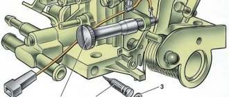
The sensor is located in the throttle body near the air intake pipe. An idle speed regulator is installed next to it.
Verification technology
To check the sensor, you first need to determine whether it is direct or reverse. So, on Daewoo Lanos cars, almost the same sensor is installed as on VAZs, only they work in different directions. That is, in the closed position of the damper it can produce 5 volts, or maybe 0.5 if the graphite contact tracks are turned in the other direction. Be that as it may, to check the sensor you need a multimeter and a couple of minutes of free time.
When connecting a multimeter to the sensor, it should show the minimum or maximum voltage, depending on the engine, and when rotating the throttle, change the voltage value smoothly and without jerking. If there is even the slightest dip in the readings in any range, the contact tracks have worn out and such a sensor must be replaced. That's all you need to know so that the throttle position sensor does not ruin our lives. Happy travels to everyone!
Maintenance and replacement of TPS
The practice of servicing and replacing the sensor does not change either. And all this is necessary when the diagnostic computer shows that the sensor is giving deliberately incorrect readings. Nobody repairs them; even expensive sensors are tried to be replaced entirely. Their job is too important to save on them. A faulty throttle angle sensor can manifest itself in a variety of ways. Since it works in all engine operating modes, it is not possible to immediately determine its malfunction by eye. In any case, when the first signs appear, which may include:
- instability of idle speed;
- failures when changing the speed;
- high fuel consumption;
- uneven acceleration;
- hard start,
and also in some cases when the emergency warning lamp is triggered, it would be useful to check the functionality of the sensor.
Removing the unit
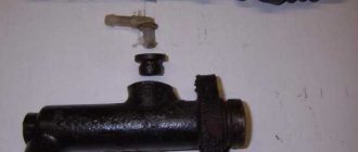
The purpose of the throttle assembly (abbreviated as DU) is to regulate the air supply to the engine cylinders. Thus, it controls the enrichment or leanness of the fuel mixture. The appearance of remote control malfunctions causes improper operation (interruptions) of the motor. If problems arise, the remote control is usually replaced with a new one, but often such problems are solved by removing and washing the remote control yourself.
What you need for cleaning
To remove and clean the assembly you will need:
- Screwdriver Set
- Head "13" with ratchet
- Old toothbrush with stiff bristles
- Cleaner
- Cotton swabs
- Latex gloves
Removal
- We remove the terminals of the VAZ battery, de-energizing the electrical network of the motor
- Disconnect the connectors from the throttle position sensor, idle speed control, and also remove the cable from the throttle valve actuator
- To avoid losses, partially drain the coolant
- Then loosen the clamp securing the air hose to the throttle body
- Then a clamp securing the ventilation hose of the 2nd circuit (crankcase gases) to the pipe on the cylinder head cover
- Now you can remove the air hose along with the crankcase ventilation hose
After releasing the clamps, remove the air hose
- Take a Phillips screwdriver and loosen the clamp, then remove the hose for crankcase ventilation (from the 1st circuit) from the remote control fitting
- Then we loosen the clamps securing the hoses that discharge and supply coolant, and remove these hoses
- Now, using the “13” head, unscrew the nuts that secure the throttle assembly to the receiver, photo below
Using a ratchet and a socket “13”, remove a pair of nuts that secure the unit to the receiver
- Then we remove our throttle assembly from the studs and loosen the clamp to disconnect the hose for purging the adsorber (this is necessary if your car has a system for collecting fuel vapors)
- Carefully remove the sealing gasket under the assembly
- If you have never carried out the steps to clean the remote control, then it will most likely be necessary to replace the gasket
- Then we unscrew the screws that hold the IAC (idle speed regulator) and then remove the regulator (don’t worry, the holes for attaching the regulator are designed in such a way that it will not be possible to mix it up when installing it)
Cleaning
Instructions for cleaning the remote control, it was not difficult to guess, require the use of a cleaning agent, with cotton swabs and a toothbrush:
We clean all channels, hidden cavities, in addition, special attention should be paid to the place for landing the IAC, as well as the area that is located next to the damper. After finishing the work, the unit should turn out perfectly clean. Don’t forget to clean the channel for crankcase ventilation at the same time. Channel size large, which is why it is most convenient to blow it with a cleaning agent. It is more convenient to blow it with a foot pump, since the diameter of the hose fitting coincides with the wheel one. And the last stage is to replace the worn out remote control pipes and blow out the rest with compressed air. Such procedures can significantly extend the life of your mass air flow sensor.
Removing and checking the idle air regulator
We remove the idle air control to check and replace. With the ignition off, release the latch.
...disconnect the engine management system wiring harness block from the regulator. Terminals “A”, “B”, “C” and “D” of the wiring harness block are connected, respectively, to terminals “67”, “66”, “65” and “64” of the controller. When the ignition is turned on, the voltage values (regulator control output signals) at these terminals change chaotically and therefore cannot be checked.
Using a Phillips screwdriver, unscrew the two screws securing the regulator to the throttle assembly...
...and remove the regulator from the throttle assembly socket.
The connection between the regulator and the throttle assembly is sealed with a rubber ring. Using a tester (in ohmmeter mode), we measure the resistance between the terminals of the regulator connector. For a working regulator, the resistance between terminals “A” and “B”, as well as “C” and “D” should be 40–80 ohms. Install the idle air control in the reverse order. Before installing a new regulator...
...using a caliper we check the distance between the end of the valve needle and the supporting surface of the regulator flange. The distance should be no more than 23 mm. This is necessary in order not to damage the regulator during installation - the regulator needle should not rest against the seat of the throttle assembly. It is necessary to take into account that if the specified distance for the new regulator is more than 23 mm, then it will be possible to retract the locking needle into the regulator only with the help of a special tester (at a service station). Before installing the idle air regulator, clean the valve seat, air duct and surface for the sealing ring in the throttle assembly. Apply a thin layer of engine oil to the new regulator O-ring.
The regulator consists of a two-pole stepper motor and a cone valve connected to it.
Based on a signal from the electronic engine control unit, the electric motor moves the valve, thereby changing the flow area of the air channel.
You will need: Phillips screwdriver, tester.
1. Press the clamp of the wiring harness block
2. Disconnect the block from the idle speed control.
3. Remove the two screws securing the regulator to the throttle assembly
4. Remove the regulator from the throttle body hole.
The connection is sealed with rubber ring 1. Do not try to pull out or push in valve 2 of the regulator, as this may damage the regulator.
5. Switch the tester to ohmmeter mode and measure the resistance between terminals “A” and “B” of the regulator, and then between terminals “C” and “D”.
The resistance should be between 40 and 80 ohms.
There are no terminal markings on the idle air control housing, but their location can be determined by the corresponding markings on the wiring harness block.
6
When replacing the regulator with a new one, pay attention to the distance L between the end of the valve needle and the mounting flange - it should be no more than 23 mm
If this distance is greater, the regulator needle will rest against the throttle assembly seat and the regulator will be damaged when tightening the fastening screws.
7. Before installing the regulator, clean the seat and air duct in the throttle assembly, as well as the surface under the regulator’s sealing ring, from dirt.
8. Lubricate the O-ring with engine oil and install the regulator in the reverse order of removal. Tighten the regulator mounting screws to a torque of 3–4 Nm.