The radio is a built-in device designed to connect to the vehicle’s on-board system and additional devices for which it acts as a head unit. To enable such communications, standardized interfaces have been developed for these purposes, providing connections to specific pins on an electronic circuit. For each such output, not only a standard interface has been developed, but also a name that simplifies search and connection. This review gives the most common decoding of radio tape recorder designations using Pioneer as an example.
Connecting the radio
Dimensions
There are two main form factors for radios, these are 1-DIN and 2-DIN (DIN (abbr.) - German Deutsches Institut für Normung eV . - German Institute for Standardization).
The depth is not standardized, but is usually 160 mm. for both options.
Today, replacing a 1-DIN radio with a 2-DIN and vice versa is not difficult, the presence of a huge number of adapter frames contributes to this, thanks to our Chinese brothers!
Conditional graphic designations in schemes. Designations for general use (GOST 2.721-74)
A characteristic feature of this scheme is minimal detail. In rooms with normal operating conditions, switches with IP20, maybe up to IP, are installed
Given such circumstances, designers adopt practical experience from more experienced colleagues; they simply know how to do many things correctly, but do not know why.
If there are no points, this is not a connection, but an intersection without an electrical connection. Moreover, there is a difference between fluorescent fluorescent lamps and incandescent lamps. Conceptual drawings are created both single-line and full.
Functions of moving contacts Basic functions can only be performed by fixed contacts. In the diagrams, the power line is depicted passing through the fuse, the resistor is drawn without internal elements. Designation of sockets in the drawings Sockets for single-phase network B are indicated in the diagrams in the form of a semicircle with one or more segments sticking up. If you need to reflect only power lines, it is enough to draw a linear diagram, but to depict all types of circuits with monitoring and control devices you will need a complete one.
Schematic diagram of a radio receiving device. Installation Unlike the above drawings, the installation diagram, in addition to indicating the elements, determines their exact position in two-dimensional space. Conventional graphic symbols of mechanical connections, drives and devices - according to GOST 2.
Installation of electrical wiring and devices in the rooms of the home Graphic symbols in electrical circuits of UGO on functional plans Switching units include contact parts that operate using various mechanisms. Types of contactors The figure shows a two-contact switch.
Basic Basic Images Electrical circuits lead to devices and installations that are equipped with contacts that can break or connect these circuits. Contacts of switching devices consist of moving and fixed contact parts. Sometimes the nominal data is not indicated, in this case the element parameters do not matter; you can select and install the link with the minimum value.
If the standard does not contain the required designation, then it is compiled based on the principle of operation of the element, designations adopted for similar types of devices, devices, machines in compliance with the design principles stipulated by the standard. Image of a circuit breaker in full diagram Contact switching device. Letter designations Along with the UGO, to more accurately determine the name and purpose of the elements, a letter designation is applied to the diagrams. What does a schematic representation of pass-through switches look like? Unlike conventional switches, when using two-key models, another bar is added parallel to the top one. How to read electrical diagrams. Radio components marking designation
Wire
Adapter for radio
The easiest, safest and neatest way to connect a radio is to use an adapter.
The ISO connector is an international standard for modern car receivers.
Intro connector ISO-001 (male)
Intro connector ISO-002 (“female”)
Most likely, the Intro ISO-001 (“male”) connector will stick out from the depths of the panel of your car, its mating connector is Intro ISO-002 (“female”), which will be at one end of the adapter, at the other end there should be a connector suitable for your radio.
If you don’t have an ISO-001 plug and only have a bunch of wires at your disposal, we recommend that you figure it out and install it, which will make your work much easier in the future when possibly replacing or dismantling the receiver.
ISO adapter pinout
Introduction
But let's start a little from afar... Every young specialist who comes to design begins either by folding drawings, or by reading regulatory documentation, or by drawing “this” according to this example.
In general, normative literature is studied in the course of work and design. It is impossible to read all the normative literature related to your specialty or even a narrower specialization. Moreover, GOST, SNiP and other standards are periodically updated. And each designer has to monitor changes and new requirements of regulatory documents, changes in the lines of electrical equipment manufacturers, and constantly maintain their qualifications at the proper level.
Remember Lewis Carroll in Alice in Wonderland?
This is not my way of whining about “how hard the life of a designer is” or boasting “look, what an interesting job we have.” That's not what we're talking about now. Given such circumstances, designers adopt practical experience from more experienced colleagues; they simply know how to do many things correctly, but do not know why. They work according to the principle “That’s the way it is here.”
Sometimes these are quite basic things. You know how to do it right, but if they ask “Why is this?”, you won’t be able to answer right away, referring at least to the name of the regulatory document.
In this article, I decided to structure the information regarding symbols, sort everything out, and collect everything in one place.
Connecting the radio yourself (without an adapter)
There is no adapter or there is no desire to use it, then in detail on the pinout. 99% of manufacturers adhere to standard colors for wires and their purposes.
Inputs to the radio
- Yellow wire (BAT) - to constant +, regardless of the position of the ignition switch, directly to the battery through a 10-20A fuse.
- Red wire (ACC) - to the ignition switch terminal, where + appears when you turn the ignition key. On many cars there is already a separate wire in the block. You just need to find it (quite simply with the help of a tester or a control light). You can also connect it to any terminal where +12 appears when the ignition is turned on.
- The black wire is negative or ground, which is the same thing. It is connected to the body with a good contact (there is a permanent negative) or to the negative from the battery.
- Blue/white-blue wire (REM) is a control wire that, when the radio is turned on, automatically turns on the car amplifier or active antenna.
- The orange wire of the car radio (or variation) (ILL) - connects to the light switch terminal or to any other terminal where +12 appears when the side lights or headlights are turned on.
- Yellow - black wire (variations) (MUTE) - this is a remote switch to turn off the sound or mute it. Connects to the corresponding wire of your car Handsfree. If the kit is missing, do not connect it anywhere. This is an option and does not affect the performance of the radio or the quality of work.
Radio outputs
The outputs are basically speaker wires to the speakers. They have paired colors. A specific speaker is connected to each color pair:
White pair of wires - front left speaker;
Gray pair - front right speaker;
Green pair - rear left speaker;
The purple pair is the rear right speaker.
Each pair of speaker wires consists of a solid color wire and a wire with a black stripe. The black stripe indicates a minus. Make sure to connect the speaker wires correctly, otherwise, if the color scheme is not followed, the balance adjustment will not work correctly, and if the polarity is not observed, the speakers will play in antiphase, which will result in scattered sound.
Radio connection diagram
The radio may also have linear outputs for transmitting an audio signal to an amplifier.
Various options for schematic and letter designations of radio tape recorders of various brands
Acoustic group:
- R = Speaker right.
- L = Speaker left.
- FR+, FR- or RF+, RF- = Front speaker - right (plus or minus, respectively).
- FL+, FL- or LF+, LF- = Front speaker - left (plus or minus, respectively).
- RR+, RR- = Rear speaker - right (plus or minus, respectively).
- LR+, LR- or RL+, RL- = Rear speaker - left (plus or minus, respectively).
- GND SP = Speaker ground.
Power connector:
- B+ or BAT or K30 or Bup+ or B/Up or B-UP or MEM +12 = Battery powered (plus)
- GND or GROUND or K31 or just a minus = Common wire (Ground), battery minus.
- A+ or ACC or KL 15 or SK or S-kont or SAFE or SWA = +12 from the ignition switch.
- N/C or n/c or N/A = No contact (there is a physical pin but not connected anywhere).
- ILL or LAMP or sun symbol or 15b or Lume or iLLUM or K1.58b = Panel illumination. +12 volts are supplied to the contact when the side lights are turned on. Some radios have two wires, -iLL+ and iLL-. The negative wire is galvanically isolated from ground.
- Ant or ANT+ or AutoAnt or P.ANT = After turning on the radio, +12 volts are supplied from this contact to control the retractable antenna, if one is present, of course.
- MUTE or Mut or mu or the image of a crossed out speaker or TEL or TEL MUTE = Input to turn off or mute the sound when receiving a phone call or other actions (for example, reversing).
Other possible contacts:
Amp = External amplifier power-on control pin DATA IN = Data input DATA OUT = Data output Line Out = Line output REM or REMOTE CONTROL = Control voltage (Amplifier, Active antenna) ACP+ , ACP CAN bus lines = CAN bus line CAN-H = CAN bus line K-BUS = Bidirectional serial bus (K-line) SHIELD = Shielded wire braid connection. AUDIO COM or R COM , L COM = Common wire (ground) of the input or output of preamplifiers CD-IN L+ , CD-IN L- , CD-IN R+ , CD-IN R- the SW+ changer B = Power switch +B battery. SEC IN = Second input DIMMER = Changing the brightness of the display ALARM = Connecting alarm contacts for the radio to perform car security functions (PIONEER radios) SDA , SCL , MRQ = Communication buses with the vehicle display. LINE OUT , LINE IN = Line output and input, respectively. D2B +, D2B- = Optical audio link
In the downloads section you can find a large number of pinouts from different brands that will help you connect your radio.
What are the wires used for and where do they go?
Types of USB connectors
Wires for car radios are used to connect to a power source, speakers and amplifier, remove control signals and implement service functions. Thanks to clear identification by color, the likelihood of making a mistake when connecting is reduced, since it is clear which wires go where and what they are needed for.
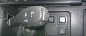
Orange
The orange wire (ILL) is most often used to control the backlight of the car radio display. It connects to the parking light switch. In this case, several backlight control scenarios are possible. For example, you can make its brightness automatically decrease when the side lights are turned on.
Yellow and red
According to the generally accepted standard, the yellow and red wires are used to connect the positive pole of the power supply to the car radio. Through the first of them, constant power is provided to the device’s microcircuits along with the audio power amplifier and display backlight. When voltage is applied to the yellow cable, all functions of the car radio begin to work. Often, its break is connected to a fuse in a housing that matches the type. The higher the output power of the car radio, the higher the rating of the fuse link.
The red wire, constantly connected directly to the battery, provides continuous power to the volatile memory chip, which stores radio stations recorded by the owner, car radio parameters and the place where listening to music from the media was stopped. The yellow wire is often connected not directly to the on-board network, but through the ignition switch. Thanks to this approach to power supply, the current consumed by the receiver is reduced several times.
Blue and pink
The blue wire is used by some manufacturers to control a motorized antenna. It is supplied with power when the radio mode is turned on. When the radio is turned off, the antenna is automatically retracted, since it contains an additional relay, which is powered directly from the battery. Another purpose of blue is to enable additional functions. For example, the Reverse wire on the radio is used to activate the parking sensors or rear view camera mode.
Pink is used to implement various service functions. One of them is blocking multimedia functions on a 2-din radio with a video player. The control signal is most often supplied from the warning lamp switch under the parking brake lever. As soon as the pink cable is connected to ground, it becomes possible to start the video player or turn on the TV tuner. Otherwise an error message will appear on the display.
Blue - white
The blue-white cable (blue wire with a white stripe) is designed to control the power of the active antenna. It is often marked with a tag marked “Remote”. This cable also supplies a control signal to the car amplifier. The connection can be made either directly to the device or through a special relay.
Connect the radio in your car efficiently. Recommendations:
If we are considering a radio to create a good, not ordinary audio system and get excellent bass, then we need to know how to connect the radio correctly. This is really important as it affects the sound quality.
- It is advisable to provide power using separate wiring, running directly from the battery to the radio, both plus and minus.
- The diameter of the supply wiring should be no less than that of the radio connector, preferably one and a half to two times thicker. The wire must be copper.
- Be sure to install a fuse on the positive wire with a cross-section no further than 15 cm from the battery terminal.
- When powering the radio, red and yellow wires are used. Yellow is intended to power the memory, and red is used to turn off the radio and assumes the presence of an output to the ignition switch. This means that after turning off the ignition, the car radio will automatically turn off. We do not recommend the option of connecting the yellow and red wires in parallel, so that the radio turns off only when you press a button on the radio panel. Sooner or later you may forget to turn it off and then your battery will suffer.
How to properly connect to an electronic device
The concept of an interface as we know it today dates back to the 1960s. More precisely, in 1964, when the company developed its legendary IBM System/360 mainframe. It was then that the main tasks of any interface - physical or virtual - were formulated. They were to provide a standard connection for all devices.
Euro connectors
Initially, only a few types of standard inputs could be made to ensure compatibility between products from different manufacturers. This was a PS/2 port for the keyboard, an LPT port for the printer, and a connector for the PCI card. Nowadays, each type of connection has its own standard interface; this approach greatly simplifies the development and sale of any type of device and allows you to understand their built-in capabilities. Here are descriptions of the main communication elements, first of all, the designation of the button on the radio, which are used on the panels of Pioneer and other car radios.
Types of branded connectors
Description of the buttons on the front panel of the radio for control (decoding)
| Button labels | Button function |
| A.F. | Different RDS frequency, automatic search when reception is poor |
| ALL OFF | Everything is off |
| AMS | Music sensor, works on the principle of playing a number of tracks equal to the number of clicks |
| ANG | Panel adjustment |
| ATA | The radio turns on automatically when you turn off and rewind media tracks |
| A.T.T. | Quickly reduces volume |
| BAND | Selecting a radio receiver |
| BEER | Enabling sound when pressing buttons |
| Blank Skip | Skips pauses longer than 8 seconds |
| BMS | Compensates for low frequencies when dropped due to the main device |
| BTM | Remembers the quality frequency of strong stations |
| CLK ADJ | Adjusts time |
| COLOR | Color |
| DISP | Display activation |
| DNPP | Selecting a CD in the changer |
| DNPS | Entering disc names |
| DSP | Activating the sound processor |
| EJECT | Remove the cassette from the cassette receiver or disc |
| EON | Reception of traffic information |
| FUNCTION | Switches the most used functions |
| INTO SCAN | Plays the recording for 10 seconds to search |
| LOS | Looks for stations, skipping with weak reception |
| LOUD | Tone compensation |
| M.RDM | Disc random playback |
| P.I. | Automatic search |
| PI SOUND | Switching to another frequency |
| PI MUTE | Muffled sound |
| POWER | Shutdown |
| PS | Listening to saved settings |
| PTY | Selecting a genre |
| RDS | Search for a station by metadata |
| RDM | Play disc tracks in any order |
| REG | Switching to the frequency of a radio station with RDS |
| Repeat Play | Replaying a track |
| SCAN | Scanning tracks and playing the beginning |
| SEL | Settings |
| SHUFFLE PLAY | Play available music in random order |
| SYSTEM Q | Tracking sound enhancement factors and showing them on the display |
| TA SEEK | Searching for a station with RDS |
| TC | Calling the tuner when rewinding |
What does EA mean in the text?
In sum, EA is an acronym or abbreviation word that is defined in simple language. This page illustrates how EA is used in messaging and chat forums, in addition to social networks such as VK, Instagram, Whatsapp and Snapchat. From the table above, you can view all the meanings of EA: some are educational terms, others are medical terms, and even computer terms. If you know of another definition of EA, please contact us. We will enable it during the next update of our database. Please be aware that some of our acronyms and their definitions are created by our visitors. Therefore, your suggestion for new abbreviations is welcome! As a return, we have translated the acronym of EA to Spanish, French, Chinese, Portuguese, Russian, etc. You can further scroll down and click the language menu to find meanings of EA in other 42 languages.
Security and fire panel “Contact GSM-9N” (What does gnd mean in the diagram)
“What does gnd mean on the diagram” in pictures.
About power decoupling with examples / Geektimes
Did Prestigio see the mouse through a homemade OTG cable before? Perhaps that mouse consumed less. Have you tried connecting a flash drive via a cable?
USB pinout | Computer hardware circuits
GG (GND, Ground) body, common (output) GAIN gain Gain look gain level Gap. gap, interval (interline) gate pulse, strobe pulse GEN (generator) generator GRN (ground) grounding Guard band protective frequency band, guard interval (between recording lines) Guide pin key (direction and reference point of IC pins, lamp marker holes in LPM gears)
Car radio connectors and their designations
I came across a lot of basic electrical diagrams on devices connected to a computer, where Vcc and Vdd are interchangeable.
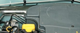
In a Chevy Niva car, the main connection point of the harnesses to ground is in the upper left part of the engine shield on the passenger compartment side, also on a welded stud. To access the connection, you need to unscrew the decorative cover covering the mounting relay and fuse block and this block itself. Another problem area of the Chevy Niva is the power mass of the battery, which is screwed to the body next to the chain tensioner.
There are also 7 ground wires on the ECU mounting bracket. In the photo, the ECU has been removed for clarity.
By the way, the word “output” (English “pin” - pin) is used in electronics for microcircuits, transistors, capacitors, diodes, resistors, optocouplers, inductors. The word “contact” is for connectors, switches, jumpers, relays, jumpers, but the slang names “legs, legs” are more characteristic of a person than an electronic product.
So today we learned another lesson about attenuation and also learned about the Breadboard.
But you can't collect much this way. Complex circuits require more space. In such cases, the individual components of the circuit are connected using a wire. For a better connection of the wire, it is advisable to use soldering. We don’t know how to solder, and it’s a chore. After all, if the circuit is complex and we made a mistake somewhere, then we will have to desolder and solder everything again.
Depending on the rise time of the switching pulses, a given capacitor can be composed of several capacitors of different ratings in order to cover a larger frequency range. The blocking capacitor connected to the VCC pin should also be placed as close to this pin as possible. It is possible that this capacitor will also need to be made up of several capacitors. For the most efficient heat removal, several vias should be provided under the metal base of the microcircuit (exposed pad), providing thermal communication with the earthen polygon.
There are technically six legs on the button. They are connected in pairs. If the button is pressed, some pairs are connected. If pressed, others.
That is, contacts A8 to E8 are (always) connected internally, but, say, A8 and F8, B5 and B6 are not. But we can connect them ourselves.
Fixed resistors
The name of constant resistors is associated with their nominal resistance, which remains unchanged throughout the entire period of operation. They differ depending on the design and materials.
Wire elements consist of metal wires. In some cases, high resistivity alloys may be used. The basis for winding the wire is a ceramic frame. These resistors have high nominal accuracy, but a serious drawback is the presence of a large self-inductance. In the manufacture of film metal resistors, a metal with high resistivity is sprayed onto a ceramic base. Due to their qualities, such elements are most widely used.
The design of carbon fixed resistors can be film or volumetric. In this case, the qualities of graphite as a material with high resistivity are used. There are other resistors, for example, integral ones. They are used in specific integrated circuits where the use of other elements is not possible.
Connector pinout (decoding)
The connector pinout is the only element of the power interface that has an individual circuit. In other words, the interface is always different and depends on the specific model of the radio, but the pinout designation of the radio is always the same. The description is usually given in the documentation.
Connector pinout
There are methods for determining pin outputs experimentally if it is impossible to obtain an original description of the contacts. This is typical for Chinese devices produced under fly-by-night brands. The need for restoration is often necessary, since the device turns out to be of really good quality and can still be used for media purposes.
Detailed description of connectors
Description of control connectors
The operating instructions contain the usual diagram with symbols, the description of which is given below. The data should take into account the names of the radio contacts that are located on the rear panel. There is no universal option, since the more interfaces, the more extensive functionality is supported. Pioneer practices a large number of interfaces, others do not.
But quantity is not a panacea, but only one of the options for interface elements. The best way to understand what has been said is with the help of an illustration showing connectors for ToyotaPrado. The designations on the pinout are described in the instructions for the radio and are given below.
Name of wires and power outputs of the car radio
| BAT, K30, Bup+, B/Up, B-UP, MEM +12, BATTERY | Battery powered |
| GND, GROUND, K31, minus | Wire to ground |
| A+, ACC, KL 15, SK, S-kont, SAFE, SWA | Power supply from ignition |
| N/C, n/c, N/A | Blank contact |
| LAMP, 15b, Lume, iLLUM, K1.58b, “sun”. |
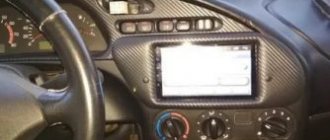
How to connect the front panel if nothing is clear at all
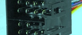
Look at the photo below:
Here is a good example - the old type of wiring, and also my least favorite. Firstly, nothing is signed, and secondly, the contacts are not arranged in any way, and it is not clear which of them form pairs.
There are two solutions to the problem:
Solution number two:
If there are no instructions, you can use the following method: connect the computer to the electrical network, and then, one by one, briefly close adjacent pairs of contacts with a screwdriver. When the computer starts up during the next short circuit, that pair of contacts is responsible for the Power button. The reset button is located in the same way, only when the computer is running (when the contacts for the Reset button are closed, the computer will reboot)
You will have to search for indicators of hard drive operation and computer operation using the “plug and play” method until they work.
Note: I have been using this method for quite a long time, and have not damaged a single motherboard yet
I advise you to be extremely careful - I am not responsible for lost boards due to your negligence
This concludes my analysis of the front panel connections. There are many more interesting and useful articles planned in the future - subscribe to updates to keep abreast of events on the site.
All EA definitions
| Acronym | Definition |
| E.A. | EN Anderen |
| E.A. | Ecole de l'Air |
| E.A. | Eigenmachtig Abwesend |
| E.A. | Ejercito del Er |
| E.A. | Electronic Arts |
| E.A. | Ensiapu |
| E.A. | Enterprise Agreement |
| E.A. | Epreuves d'Artiste |
| E.A. | Employee agent |
| E.A. | Environment Agency |
| E.A. | Alternative Enlazando |
| E.A. | Impact Analysis |
| E.A. | Engineering analysis |
| E.A. | Real estate analysis |
| E.A. | Entreprise Adaptee |
| E.A. | Argentine Army |
| E.A. | Architecture of the ensemble |
| E.A. | Enterprise Architecture |
| E.A. | Entrepreneurs Association |
| E.A. | Endometriosis Association |
| E.A. | Endless centuries |
| E.A. | Everywhere access to |
| E.A. | Eternal Arcadia |
| E.A. | External relations |
| E.A. | External access |
| E.A. | External partner |
| E.A. | External alarm |
| E.A. | Excitation of autoionization |
| E.A. | Educate America |
| E.A. | Eastern Airlines |
| E.A. | Enemy planes |
| E.A. | Elective abortion |
| E.A. | Equipment leveling |
| E.A. | Enemy actions |
| E.A. | Escrowed authenticators |
| E.A. | Jeff Ellis & Associates |
| E.A. | Access to employment |
| E.A. | Exchange Access |
| E.A. | Evangelical Union |
| E.A. | Euclidean algorithm |
| E.A. | European cooperation on accreditation |
| E.A. | Employment benefit |
| E.A. | Registered Agent |
| E.A. | Enrolled actuary |
| E.A. | Environment protection |
| E.A. | Earth Alliance |
| E.A. | Action Land |
| E.A. | Euro area |
| E.A. | Study for aphasia |
| E.A. | Engineering Analysis |
| E.A. | Engineering Authorizations |
| E.A. | Engineering assistant/assistance |
| E.A. | Engineering Ambassadors |
| E.A. | Engineers Australia |
| E.A. | Execution of the agreement |
| E.A. | Executing agency |
| E.A. | Executive agent |
| E.A. | Executive Assistant |
| E.A. | Executable architecture |
| E.A. | Ethan Allen |
| E.A. | Every |
| E.A. | Ever active |
| E.A. | Purpose of engineering |
| E.A. | New adult life |
| E.A. | Areas of interaction |
| E.A. | Exclusion area |
| E.A. | Education Austin |
| E.A. | Environment Australia |
| E.A. | Threat Assessment |
| E.A. | Evaluation authority |
| E.A. | Educator Ambassador |
| E.A. | Transfer area |
| E.A. | Edgewood Square |
| E.A. | Energy Absorption |
| E.A. | Journeyman |
| E.A. | Authority to approve expenses |
| E.A. | Technician assistant |
| E.A. | Technician assistant |
| E.A. | Estimated average |
| E.A. | Equal |
| E.A. | Equal access |
| E.A. | Early Action |
| E.A. | Early availability |
| E.A. | Early access |
| E.A. | Early adoptive parent |
| E.A. | Extended bit address fields |
| E.A. | Extended address |
| E.A. | Extended attribute |
| E.A. | Advanced Mechanism |
| E.A. | Editorial changes |
| E.A. | Private Aviator |
| E.A. | Agreement on the execution of sentences |
| E.A. | Fair adjustment |
| E.A. | Urgent confirmation data |
| E.A. | Automation technology |
| E.A. | Balanced unit |
| E.A. | Approval of appropriations |
| E.A. | Academic Administration |
| E.A. | Implementing agency |
| E.A. | Emergency announcement |
| E.A. | Emergency assistance |
| E.A. | Emergency/enforcement action |
| E.A. | Emergency Events |
| E.A. | Emergency measures |
| E.A. | Emergency powers |
| E.A. | Evolutionary acquisition |
| E.A. | Evolutionary algorithm |
| E.A. | Environmental assessment |
| E.A. | Environmental guarantees |
| E.A. | Environmental audit |
| E.A. | Economic issues |
| E.A. | Economic analysis |
| E.A. | Experimental activities |
| E.A. | Experimental Agent |
| E.A. | Expert |
| E.A. | Electric drive |
| E.A. | Electro absorption |
| E.A. | Electromagnetic anomalies |
| E.A. | Electronics Assembly |
| E.A. | Electronic attacks |
| E.A. | Electronic analysis |
| E.A. | Electric Power Association |
| E.A. | El Alacran |
| E.A. | Emotional romance |
| E.A. | Activation energy |
| E.A. | Alpha energy |
| E.A. | Electron affinity energy |
| E.A. | Encyclopedia Americana |
| E.A. | Episodic ataxia |
| E.A. | Eskilstuna, city, Sweden |
| E.A. | Escrow account |
| E.A. | Effective address |
Resistors
Resistors include radio components that have a strictly defined resistance to the electric current flowing through them. This function is designed to reduce the current in the circuit. For example, to make a lamp shine less brightly, power is supplied to it through a resistor. The higher the resistance of the resistor, the less the lamp will glow. For fixed resistors, the resistance remains unchanged, while variable resistors can change their resistance from zero to the maximum possible value.
Each constant resistor has two main parameters - power and resistance. The power value is indicated on the diagram not with alphabetic or numerical symbols, but with the help of special lines. The power itself is determined by the formula: P = U x I, that is, equal to the product of voltage and current
This parameter is important because a particular resistor can only withstand a certain amount of power. If this value is exceeded, the element will simply burn out, since heat is released during the passage of current through the resistance
Therefore, in the figure, each line marked on the resistor corresponds to a certain power.
- On the circuit diagrams, the serial number is indicated in accordance with the location (R1) and the resistance value is equal to 12K. The letter “K” is a multiple prefix and means 1000. That is, 12K corresponds to 12,000 ohms or 12 kilo-ohms. If the letter “M” is present in the marking, this indicates 12,000,000 ohms or 12 megaohms.
- In marking with letters and numbers, the letter symbols E, K and M correspond to certain multiple prefixes. So the letter E = 1, K = 1000, M = 1000000. The decoding of the symbols will look like this: 15E - 15 Ohm; K15 – 0.15 Ohm – 150 Ohm; 1K5 – 1.5 kOhm; 15K – 15 kOhm; M15 – 0.15M – 150 kOhm; 1M2 – 1.5 mOhm; 15M – 15mOhm.
- In this case, only digital designations are used. Each includes three digits. The first two of them correspond to the value, and the third - to the multiplier. Thus, the factors are: 0, 1, 2, 3 and 4. They indicate the number of zeros added to the base value. For example, 150 - 15 Ohms; 151 – 150 Ohm; 152 – 1500 Ohm; 153 – 15000 Ohm; 154 – 120000 Ohm.