02/04/2021 7,564 Video and media devices
Author: Ivan Baranov
Recently, more and more of our compatriots are paying attention to the arrangement of speaker systems in their cars. Today, there are many solutions to ensure high-quality sound from car radios. From this material you can find out what the ISO connector of the radio is and what its pinout is.
[Hide]
Pinout
Explaining in accessible language which color wire is responsible for which function in the device. The pinout can be presented as:
Description in free form. It is this form of representation of the pinout of car players from Pioneer (Prology 1715t), Sony, Kenwood, Hyundai, JVC, Mystery) that we will use in this information article.
ISO connector is a contact technical device for connecting electrical wires along their groups of eight contacts (16), in two or one rectangular housing.
The brown block connects the wiring for the speaker system and sometimes its control (control of changing radio stations or musical compositions from the steering wheel of a car).
Black block - power (electrical) supply of contacts between the car and the sound-reproducing device.
Sometimes the contacts are combined in one connector, and they are separated into groups in the upper and lower parts of a single housing. ISO is a generally accepted technical standard for goods and services developed by an international organization for standardization.
ACC is a connection that allows you to listen to music and radio without starting the car.
Features of ISO connectors
Having a single ISO connector standard (electrical characteristics), many automakers, as well as audio equipment companies, can change its external shape at their discretion. That is, if you decide to replace an outdated Hyundai radio with a Mystery multimedia system, first of all, pay attention to the matching iso connection formats.
Also, when installing equipment, you can quite often encounter slight changes in the pinout colors of electrical cords from the standard pinout. Next, we will provide visual descriptions of the pinout of the ISO connector of a standard sample and for individual brands of sound-reproducing equipment (pinout of the ISO connector of the Prology 1715t radio, etc.). Judge for yourself how different they are from each other.
An alternative to ISO connectors are Fakra connections.
Standard form of wiring connections
Upper part of the connector (socket numbers and wiring colors):
- Changing the sound volume when the car is moving - a free-color wire.
- Muting the sound (MUTE) when there is an incoming phone call - a free-color wire.
- Empty nest.
- ACC - power supply 12 volts - wire color yellow.
- Power supply for the radio antenna (12V) - wire color is blue.
- Car radio display backlight - wire color is orange.
- Turning on the ignition - the wire color is red.
- Ground (grounding) - wire color is black.
- Increasing the volume of the right rear speaker - color purple.
- Reducing the volume of the right rear speaker - purple and black.
- Increase the volume of the right front speaker - gray color.
- Reducing the volume of the right front speaker - gray and black.
- Increase the volume of the left front speaker - color white.
- Reducing the volume of the left front speaker - white and black.
- Increase the volume of the left rear speaker - color green.
- Reducing the volume of the left rear speaker - green and black.
The official name of the pinout is ISO 10487 (Euro connector).
Standard pinout of the Prology car radio ISO connector
- Purple wire - increases the sound of the right rear speaker.
- Purple, black - decrease the level of the right rear speaker.
- Gray wire - increase the volume of the left rear speaker.
- Gray, black - decrease the sound on the rear left speaker.
- White wire – increases the sound of the left speaker (front).
- White, black – sound on the same speaker.
- Green wire - increases the sound of the right front speaker.
- Green, black - reduce the volume of the left front speaker.
- The yellow wire is powered from the car battery.
- Orange—backlit control keys.
- Blue and white - antenna power.
- The red wire is the ignition switch.
- Black wire - minus (ground).
Connections for some car models and receivers may vary slightly. To what extent these differences are fundamental and can affect the connection of sound-reproducing equipment, you can judge after reading the description of the pinout using the example of a car radio from the Pioneer brand.
Pioneer radio ISO connector pinout
When buying a used car, many drivers want to replace the standard radio (Prolozhi) with a device of a higher level (Pioneer). And they are faced with such a problem as mixed up wiring on homemade twists or with connectors that are not suitable for the Pioneer.
The way out of this situation is quite simple (at least in words). To do this, you just need to purchase an ISO standard connecting device and pin it out according to our recommendations. Due to the fact that all modern car radios have standard ISO connections and rectangular plug boxes on the rear panel, there should be no problems with the connection after pinout.
So, the pinout of the ISO connector of the car radio through 2 Pioneer blocks is done in this way:
- Block with upper contacts, letter B.
- Increase (decrease) the sound reproduction level. The color of the electrical wire is any.
- The wire that mutes the sound, for example, when there is an incoming phone call, etc., is also a free color.
- ACC mode (connected to the car ignition, + appears when you turn the key and disappears when turned off), yellow color.
- Twelve-volt power supply for the radio antenna - blue wire.
- The orange wire is responsible for illuminating the display of the car player.
- Car ignition - red wire.
- Ground – wire with black insulation.
- Bottom junction box - A.
- + right rear speaker of the multimedia system - purple wire.
- Minus - black, purple wire for the left speaker.
- Front right speaker, volume increase—gray wire.
- Right front column. Reduction - black, gray wire.
- The left column (front), plus - the wire color is white, negative - black and white wires.
- Both speakers located at the back (increase, decrease volume), green and a combination of black and green.
Since 2000, some manufacturers of European passenger cars (BMW, Ford, Mercedes, Peugeot, etc.) began to use a 40-pin Euro connector called Quadlock or Fakra. At the same time, the pinout according to wire colors remained the same for the main (named) functions.
Kenwood radio ISO connector pinout
From this manufacturer (Kenwood) we were able to find several differences in the colors of the electrical wires and their purpose for the upper part of the connector block. The lower one, acoustic, fully complies with accepted standards. In order not to repeat ourselves, by default, the contact and option numbers we missed are also standard, as for all car head units. So, in our opinion, the following changes were minor:
- The yellow electrical wire goes to the car battery.
- The red cable goes to the ignition switch (ACC mode).
- Black braided wire - standard (grounding, ground).
- Blue and white wire - regulate power.
- A wire with a color combination of orange and white – adjusts the brightness of the car radio screen backlight (DIMMER).
Pinout problems
As a rule, no unexpected situations arise when connecting a car player via Euro connectors of the ISO 10487 standard. But only under the following conditions!
Your car is equipped with an ISO connection, both on the radio (a standard output for all global brands of this type of equipment) and on the side of the standard car electrics. This means that the previous owner (the car is not new) was not an experimental electrician, that is, he did not change the wires in the connection box or individual fragments of wires at his own discretion.
If the player was manufactured by someone unknown and where, like the connector itself, in such a situation you will need to arm yourself with a digital tester, brush up on your knowledge of electrical engineering and ring all the contact groups yourself. Based on the measurements, you can determine the power values of the wiring.
What types of car radio connectors are there?
Pinout of ISO connectors for car radios
Not so often, but it still happens that almost every car owner is faced with the problem of do-it-yourself installation and subsequent independent connection of the head unit (car radio) to the standard acoustic circuit of his car. It would seem that this could be confusing, because everything is simple there! Yes, this statement is true. But, as experience shows, this confidence lasts until manipulations with the wires begin, during which the “handy” car owner begins to understand that he urgently needs pinout of Euro connectors for car radios, or even better, complete instructions for connecting the car radio.
Head unit connector pinout
One of them is the antenna. But don’t be upset, because to install and connect the car radio, you need to find the right connector in the store and use the instructions to connect the radio to the car.
To connect a passive one, just insert its plug into the socket.
A good solution would be to purchase stranded copper wires with silicone insulation. Also in each bundle there is a wire without a plus strip and with a minus strip.
Done, you got rid of the old device - you can install a new one. Connecting speakers This procedure is carried out carefully and carefully, since not only the purity of the sound depends on this, but also the operation and durability of the radio and speakers.
As for the ISO connectors, they are much more convenient. Next are the connectors.
The described circumstances are a sign of incorrect phasing. With this connection, the PG works constantly, and if the car is parked for a long time, you can simply press the button and stop power from the battery.
Detailed car radio connection diagram First, you should understand the connection of the black and yellow wires. How to find the wire pinout and connect the MYSTERY MCD 664MPU car radio without a chip
Markings and types of connectors
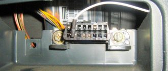
To answer your silent question about what kind of connectors there are in car radios, I must answer that most modern car radios are equipped with two standard connectors, designated by the abbreviation “ISO”. Each of these connectors is designed as an eight-pin rectangular plug, sometimes they are combined into one housing (see photo).
Car radio ISO connector pinout
One of the connectors carries “power” circuits, that is, current consumption sources are connected to it, and is designated in the diagrams as a connector under the letter “A” and is colored brown. The second connector is intended for connecting the car’s acoustic system, in other words, speakers. Unlike the previous one, it is made in black and is designated on electrical circuit diagrams as connector “B”.
What connectors do car radios have?
Sometimes there are car radios with three connectors, but this is the exception rather than the rule. The same exception as non-standard connectors, which still have wiring with standard markings and in any case allow you to connect the wires of a standard speaker system with non-standard “connections” in at least two ways. So:
- “Skolkhoz”, namely, cut off the non-standard plug and overlap the wires, which “is not very good”, since over time the twist will become loose due to oxidation/shaking and, in the best case, you will have to do all the work again while simultaneously replacing the fuses.
Pinout of ISO connectors for car radios
- Buy an adapter (the price of which is in no way close to the amount of work that the method described above includes) and, without any problems, decorously/nobly, connect the car radio with other elements of the acoustic circuit of your car.
The choice of adapters at the moment is huge, and it is simply physically impossible for any troubles to arise in the use of this variety.
Car radio ISO connector pinout
Adapters for ISO connectors
Cutting off a non-standard standard plug and connecting the wires directly is not recommended, because over time the connection will become loose, may oxidize, you will have to solder not only the wiring, additional repairs will be required, replacing blown fuses. Sometimes there are acoustics with three outputs, but they have standardized markings and electrical circuits that allow you to connect standard cables to the device using pinouts. You can buy any type of adapter for ISO connectors from one model to another.
We recommend: Rules for operating a car air conditioner: what do you need to know?
The car may not be equipped with connectors, then you need to connect the radio connector to the cable directly. This is done by twisting, soldering, or using a terminal block that does not require subsequent insulation. When twisting and soldering, heat shrink tubing is used for safe use of the equipment.
Pinout of a standard Euro connector
Let's look at the pinout of the Euro connector on a standard ISO plug - 10478
Upper power connector “A”
As already mentioned, this plug connects the sources and consumers of electrical current from the vehicle’s on-board network.
Despite the fact that it has eight contacts, not all of them can be used in the car radio connection circuit. Let's figure out what the purpose is and what task each of these contacts performs:
- Connectors No. 1, No. 2, No. 3 and No. 6 are rarely used by default in the circuit of a budget car radio. Most often they are used to connect additional functions in more professional versions of the head unit, which significantly increase the comfort of a modern car, while the colors of the wires can be made in various color variations.
For example, among the additional functionality we can highlight the following:
- “ANT” output, which is used in cases where a retractable automatic antenna is installed in the car;
- “REMOTE”, which allows you to connect external amplifiers to the car radio, which means increasing the number of connected speakers (relevant for cars with a large interior, since in a small interior a large number of speakers creates a large load on the hearing organs, which is fraught with negative consequences);
- the “ILLUMINATION” option, which automatically, depending on the speed of the vehicle, controls the light signaling of the car radio - at higher speeds, the brightness of the display decreases and does not distract the driver from the process of driving the vehicle; when the vehicle stops, it returns to its initial parameters, which significantly the extent to which it affects road safety;
- as well as the currently very common “MUTE” option, which is turned on when using a mobile device connected to the car’s speaker system - when a receive/call signal passes through, the car radio automatically activates this output, which leads to a decrease in the volume of the music being played or to a complete shutdown car radio sound;
- Contact number four (indicated on electrical diagrams as “A4”) is responsible for turning on the entire acoustic system of the car. Through a separate fuse, this yellow wire is connected to the ignition switch terminal and is already powered from the battery.
Organizing the connection of the car radio according to this scheme is guaranteed to protect the battery from unauthorized discharge, since turning on the car radio is possible only when the key is turned in the ignition switch.
Reference. The need for this kind of connection arose due to the fact that the cascades of the car audio system continue to consume electrical energy even when turned off, which very often led to battery discharge.
Domestic car enthusiasts have improved the wiring diagrams for car radios as best they can, resorting to both manual toggle switches and installing an automatic relay to turn off the radio when setting the car alarm. But, as we see, it is this connection scheme that has received universal recognition. So:
- The fifth wire (A5), blue, is responsible for connecting the car antenna. It is designed for a maximum output current of 300 microamps, and if this value is exceeded, a large current can damage not only the output amplifier stages, but also the car radio itself as a whole;
- The contact with the positional designation “A7” in red is responsible for delivering voltage to the volatile memory of the car radio. This means that if you accidentally turn it off, all device parameters will be reset/reset to factory settings. The voltage on this wire is 12 volts;
- Well, the last wire of this connector, running in black insulation (A8), as you probably already guessed, is responsible for connecting the device to the ground of the car.
Advice! In order to protect the acoustic circuit, each of the supply wires must be equipped with a fuse-link. If periodic interruptions still occur during the operation of the head unit, then it is recommended to install a capacitor between contacts “A7” and “A8”, the capacity of which is selected experimentally. Essentially, it (the capacitor) will serve as a filter that will smooth out fluctuations in the electrical power circuit of the car's speaker system.
Bottom acoustic connector “B”
As already mentioned, all other peripherals of the car audio system, that is, speakers, are connected through connector “B”. The pinout of the car radio Euro connector under the letter “B” looks like this (see previous photo):
Pinout of Android radio 8.1, 2 DIN from China, 1 DIN circuit
Android radio pinout
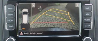
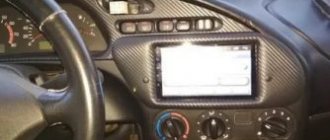
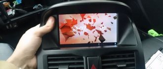
Android radios in cars are not uncommon these days. These are, rather, not radio tape recorders, but real multimedia combines. After all, they can reproduce any kind of video formats and play any kind of music. You can install any application on them, be it navigation, or even some game, and you can connect one or a pair of joysticks to it using Bluetooth technology and play in the parking lot with a friend! Of course, you can connect a rear view camera to them. And this is far from a complete list of all the skills of such multimedia car radios. Of course, such devices also have disadvantages; they are very pronounced on cheap devices. These are mainly all sorts of glitches, defects, bad sound and crookedly installed android.
The operating system now is most often Android 8.1 or 7.1. There are, of course, different copies with different versions, but their essence, like the connection and pinout, is identical. Generally. Usually, the “Chinese” have their own vision of beauty and they have their own type of connectors, but you can also find Euro-ISO connectors. Connecting a radio with a Euro connector will be easier, but Chinese connectors should not cause any trouble.
Pinout of the radio on 8.1 Android
If you recently ordered a multimedia device on Aliexpress, this pinout diagram will be extremely useful to you, because most likely it will suit you perfectly. Of course, one pinout will not be enough. We need to know which wire of the Chinese Android radio will be responsible for what, well, let’s take a look.
Color value of radio tape recorder wires on Android
Of course, the colors and meanings of the wires on a Chinese radio will most likely not match the wires on your car. To find out the meaning of your wiring, we suggest looking at the article about the pinout of the radio of your brand on our website. We most likely have one. There we make sure to indicate the meaning of the wires of each color.
Adapter for connecting a radio to Android
Next, to connect a multimedia radio from the Middle Kingdom, you will need a plug to connect the wiring. This should be included with the radio, but it may not suit you, or it may be an adapter for the Euro ISO connector. There is no need to be sad. After all, you can purchase an adapter for your car to ISO. Yes, such “dancing with a tambourine” may be necessary, but believe me, this is far from difficult and rather depends on the brand of the car.
Pinout of radio chip/plug, color meaning of wires, video
To consolidate the material and better understand, let's look at the pinout of the radio chip/plug, the color meaning of the wires, first in the photo and then in the video.
The meaning of car radio wires from Aliexpress
Android radio connection diagrams
Pinout of a complex, multifunctional multimedia system on Android, purchased on caring Aliexpress, is a rather complicated process, but do not forget about the placement and connection diagram of such a radio. After all, sometimes difficulties can arise with her. Let's look at a few schemes.
Android radio connection diagram
A little more detailed connection diagram
Video of connecting a radio on Android
The diagram is, of course, visual and good, but, as they say, it’s better to see once. Therefore, I suggest you watch the video of connecting the radio on Android.
Connection diagram for AUX video and subwoofer
Of course, you definitely need to know which wires and connectors are responsible for connecting the AUX and subwoofer on 2 DIN Android radios.
AUX video outputs and subwoofer connection to Chinese Android multimedia system
And, of course, a video on how to connect a subwoofer to a Chinese radio:
Well, as you can see, connecting a car radio, or better yet, a multimedia system for Android made in China, is so easy. The pinout is quite complex due to the multifunctionality of the device. We tried to collect a sufficient amount of information and present it as clearly and in detail as possible, so as not to confuse you. I hope you found this article useful and connecting a 2 DIN Android radio with Aliexpress pinout will now not be difficult for you, as will using AUX and installing a subwoofer to the car audio system. We wish you good luck and pleasure from using your radio, so that it gives you only positive emotions. We'll probably end here. See you on the pages of our website!
Standards 1DIN and 2DIN
The differences between them are the height of the radios. The number 2 in the designation of the 2DIN standard indicates that the height of a double-DIN receiver is 2 times greater than a device made according to the 1DIN standard. The latest radios are now the most popular and widespread. Installation of double-din radios is not possible in every car, since an appropriate seat must be provided on the front panel.
All car radios are divided into two types: with a proprietary connector, most often made in the form of a plug, and located on the rear wall, and with a universal ISO connector. In the first case, you should purchase a proprietary connector for the radio, the pinout of which matches the desired model. If the machine has an ISO socket, then the other end of the proprietary cable should also have an ISO plug. In the second case, the radio is connected directly to the ISO socket located in the car.
When replacing the radio with another one, you should look at the back wall and determine which block is located there. After this, you can decide whether to purchase a proprietary plug or you can connect the device to the machine through an already installed ISO socket. The pinout of the car radio connector is carried out according to the ISO 10487 standard.
Dual ISO connector
Some vehicles have a double plug for the speaker head unit. In this case, cable routing is carried out according to the same scheme as with separate blocks.
This design consists of 2 halves of a plug, which are attached to each other with a common clamp and separated by a plastic jumper. To correctly connect such a device, a guide groove is provided in the design. It eliminates the possible risk of incorrect installation.
ISO pinout
Many new radios increasingly use a Euro connector. It is a rectangular sixteen-pin plug consisting of one or two equal parts. An ISO plug is installed on the car, allowing you to connect any car radio that has the appropriate connector. The ISO pinout does not depend on the radio model equipped with such a connector.
Upper power connector A
It is used to supply current from the vehicle's on-board network, as well as to remove power from an active antenna or amplifier, to mute the sound and supply a backlight control signal. According to the standard, wires are marked by color:
- yellow - direct connection to the vehicle’s battery; it also supplies power to the receiver’s RAM, which provides storage of settings specified by the user;
- red - it supplies the main power;
- black is ground, the negative pole connected to the GU body;
- blue with a white stripe - when the car player is turned on, 12 V is supplied to the active antenna amplifier or the remote control controller of the car audio power amplifier;
- orange - a signal is sent to it from the vehicle’s side light switch to control the backlighting of the keys and display;
- brown - used to mute the sound, for example, while talking on the phone.
It is worth considering that two power supply systems are used. In the first case, the yellow and red wires on the pinout are connected together. The power supply to the radio does not depend on the position of the ignition key.
If you leave the car player on without a protection timer, the car battery may quickly drain.
The second system involves connecting the red wire through the ignition switch, and the yellow wire directly to the on-board network. Thanks to this, the power supply to the radio is connected to the position of the key. When the ignition is off, you can remove or insert the CD. It also keeps the audio system's built-in clock running and saves settings such as sound settings and radio channels.
The pinout of the ISO connector of the radio, intended for power supply, is carried out as follows. Pins 1, 2 and 3 are reserved and are used by some head units to enable additional functions. Pin 4 is connected to the yellow wire, and pin 5 is connected to the blue/white wire. An orange wire is connected to pin 6. Pin 7 is connected to the red wire, and pin 8 is connected to the black wire. This connector is often painted brown.
Bottom speaker connector B
It is used to supply amplified sound from the car player to the speakers. The wires through which alternating current directly flows from the microcircuit are solidly colored, and the wires connected to ground have black stripes. Color marking is carried out as follows:
- the white wire connects to the left front speaker;
- the gray wire connects to the right front speaker;
- the green wire connects to the left rear speaker;
- The purple wire connects to the right rear speaker.
The pinout of the radio chip intended for connecting speakers is done as follows:
- purple wires connect to pins 1 and 2;
- gray - to pins 3 and 4;
- white - to pins 5 and 6;
- green - to pins 7 and 8.
What is an ISO connector?
The ISO connector for the radio is a plug for connecting an audio system, certified according to European standards. In fact, such a device is an analogue of our domestic GOST. It should be noted that most modern audio systems are equipped with just such connectors, usually there are two of them. Moreover, each of them is made in the form of an 8-pin plug, but depending on the manufacturer, both plugs can be combined into one design.
One of these car radio connectors is equipped with power circuits, since voltage sources must be connected to it. Such outputs are marked with the letter A and are usually made in gray (brown) color. As for the second connector, its purpose is to connect acoustics or speakers. Such outputs are marked with the letter B and are usually painted black.
Types of ISO connectors according to radio models
Some vehicle models have sound systems with three outputs. But such connectors can be called the exception, but not the rule. In any case, even if the radio has a non-standard connector, it can still be connected to the car’s speakers. For this, either an ISO adapter can be used, or the connection can be made directly by cutting the pins and connecting them directly.
Of course, adapters for car radios are a more preferable option, since in this case the car owner will be able to dismantle the head unit at any time and replace it with another. If you do not use an adapter, but connect the car radio directly, then later to replace the audio system you will need to cut the wires and still install the adapter. Well, or you will again cut the connector on the new radio and connect it to the car’s on-board network directly.
Pinout diagrams for radio tape recorders from popular manufacturers
Wiring of linear outputs on a standard radio can be done using two RCA connectors. This option is the most common, since power amplifiers have the same sockets. The pinout of connectors for Pioneer car radios contains from 10 to 20 contacts. Their purpose depends on the model of the multimedia device. For example, in the KEH series, the first pin is the antenna control, the second pin is the voltage from the ignition switch, etc. The speakers are connected to pins 3, 4, 5, 6, 8, 9, 10 and 11.
If the car radio is without a plug
If the vehicle does not have ISO connectors for car radios, the car owner can install them himself. To do this, pinout is performed in the following order.
- If the plug is missing only in the car, you need to purchase an ISO connector from a specialized store. It must match the plug on the head unit that will subsequently be installed. If the plug is missing from the radio (in its place there is a bundle of wires), then you need to select a block.
- The first to be separated are the wires responsible for supplying voltage. Most often, they are distinguished by an increased cross-section and insulation in red and black colors. You can verify the correct choice using a test device.
- Separate the wires for the speakers according to the car's electrical diagram. During the connection, it is prohibited to connect the negative wires to the common line or ground.
- Separate the wire necessary for the antenna to operate.
- After the linear outputs on the radio are designated, they are connected to the rods of the new connector. To do this, the bare ends of the wire are secured with a crimping tool. This technique ensures reliable fastening.
- After connection, you should check the functionality of the device.
Pinout of a standard Euro connector
The Euro connector is a standard plug for many modern devices. An ISO plug is installed on the machine, thanks to which it becomes possible to connect any model of radio with the appropriate connector.
Standards 1DIN and 2DIN
The difference between the standards lies in the size of the devices: a 2-din device is 2 times higher than a 1-din device.
The most common are 1-DIN radios, because Installation of higher devices due to the lack of a seat of appropriate size on the front panel of the car is not possible in every car.
There are 2 types of radio tape recorders:
- With proprietary connector. You need to choose a product whose pinout matches the desired car.
- With universal connector. The device connects directly to the ISO socket provided in the car.
Pinout is carried out according to ISO 10487 standard.
Upper power connector A
The connector serves as a connector between sources and consumers of electricity from the on-board network.
Plugs 1, 2, 3, 6 are rarely used in radio circuits of the lower and middle price segments. The elements are used when connecting additional options in higher quality player models. Wire colors may vary.
You should understand the purpose of the contacts:
- ANT. Used with a retractable antenna.
- Remote. Designed for connecting external amplifiers. Thanks to it, you can increase the number of mounted speakers, which is necessary in the interiors of large cars.
- Illumination. Adjusts the brightness of the player screen (the higher the driving speed, the less intense the backlight, so as not to distract the driver).
- Mute. Adjusts the sound of the device.
- A4. Turns the audio system on and off.
This connection scheme allows you to protect the battery from discharge, because turning on the system is possible only when you turn the ignition key, while the acoustic cascades consume electricity even when turned off.
The pinout of the ISO connector of the radio (European) looks like this:
- Connector A5 (blue) is for the antenna. If the permissible current value (300 µA) is exceeded, both the amplifier stages and the entire head unit may break.
- Wire A7 (red) is intended to power the head unit. When it is disabled, the settings are returned to factory settings. Voltage - 12 V.
- Cable A8 (black). Responsible for connecting the speaker system to the car.
To protect the audio system, the wires must be equipped with a fusible link. If interruptions occur in the operation of the player, you should place a capacitor between connectors A7 and A8, which will act as a filter, smoothing out fluctuations in the electrical circuit.
Bottom speaker connector B
The speakers are connected through it as follows:
- Rear right + (purple).
- Rear right - (black and purple).
- Front right + (gray).
- Front left - (black and gray).
- Front left + (white).
- Front left - (black and white).
- Rear left + (green).
- Rear left - (black and green).
Most devices are designed for 4 channels; 8 wires are used for this (2 pieces per speaker).
The sound quality of the system depends on the “flattening”. If you mix up the connectors, the device will not fail, but the radio will not work correctly.
Audio system elements should be connected with cables with a cross-section of 1.5 mm or more. Thicker wires are used on power lines.
Pinouts for various brands of cars and radios
The wiring of the linear outputs on the standard radio depends on the make of the car and the head unit.
Before pinouting the connectors of the car radio, you must read the information presented on the cover of the device and in the instructions for it.
Toyota
For a standard plug: 1 - A+, 2 - GND, 3 - BAT+, 4 - backlight, 5 - antenna adjustment, 9-16 - speakers (RR+, RR-, RF+, RF-, LF+, LF-, LR+, LR -).
Universal connector for most models: 1 - ANT, 3 - linear output LR, 4 - GND linear outputs, 5 - linear output RR, 6 - CD in LCH, 7 - CD in GND, 8 - CD in RCH, 9 - CD reset , 10 — CD clock out, 11 — CD DSPL select, 12 — CD data out, 13 — CD clock in, 14 — CD data in, 16 — A+, 17 — GND, 18 — ANT GND, 22-27 and 29- 30 — speakers (LF-, LR+, RF-, RR+, LF+, LR-, RF+, RR-), 28 — CD mute, 31 — ANT CONT, 32 — CD ACC CONT, 33 — AMP CONT, 34 — B UP .
Nissan
Standard circuit: 1-6 - speakers (LR+, RR+, LR-, RR-, LF+, RF+), 7 - A+, 8 - backlight, 9 - BAT+, 10 - LF- speaker, 11 - RF- speaker, 12 - antenna control, 13 - GND.
Honda
Standard connector: 1 - RR+ speaker, 2 - LR+ speaker, 3 - backlight, 4 - BAT+, 5 - A+, 6 - antenna control, 7-10 - speakers (LF+, RF+, RR-, LR-), 13 - GND , 14-15 - speakers (LF-, RF-).
Universal connectors: 1 - A+, 2 - BAT+, 3 - GND, 4 - empty, 5-12 - speakers (RR+, RR-, LF+, LF-, RF+, RF-, LR+, LR-).
Alpine
Alpine TDE-7823W: 1 - BAT+, 2-5 - speakers (LR-, LR+, RR-, RR+), 7 - amplifier control, 8 - antenna adjustment, 9 - GND, 10-13 - speakers (LF-, LF+ , RF-, RF+), 16 - A+.
Alpine 7190M: 2 - amplifier control, 8 - GND linear outputs, 9-10 linear outputs (R, L), 13 - antenna, 27-28 - speakers (LR+, LR- and LF-, LF+), 29 - GND, 31 - BAT+, 32 - A+, 34-36 - speakers (RR+, RR- and RF-, RF+).
Mitsubishi
For all models: 1-2 — speakers (RR+, LR+), 3 — antenna, 4 — backlight+, 5-8 — speakers (LF+, RF+, RR-, LR-), 10 — A+, 11- BAT+, 12 — backlight, 13-14 — speakers (LF-, RF-), GND — connector rim.
Kenwood KDC KRC
There are several options for pinout of the radio chip from this manufacturer, depending on the model of the device:
- KDC5040R and others: 1 - GND, 2 - A+, 3 - antenna, 5-8 - speakers (RF+, RF-, LF-, LF+), 9 - BAT+, 10 - backlight, 11 - TEL mute, 12 - EXT AMPL CONT, 13-16 - speakers (RR+, RR-, LR-, LR+).
- KRC155D: 1 - GND, 3 - A+, 5 - BAT+, 8-9 - speakers.
- KDC84R and others: 1 - input A, 2 - GND input A, 7-10 - linear outputs (L, R, R, L), 11 - input A, 17-20 - GND linear output (L, R, R , L), 25 - GND, 26 - A+, 27 - amplifier, 33 - BAT+, 34 - backlight.
- KRC752R: 1 - ANT GND, 4 and 28 - output L, 5, 18, 27 and 39 - GND outputs (L, R, L, R, respectively), 8 - backlight, 9 - BAT, 10-13 - speakers (LR -, LR+, LF+, LF-), 14 — ANT, 17 and 40 — output R, 20 — antenna, 21 — A+, 22 — GND, 23-26 — speakers (RR-, RR+, RF+, RF-), 36 and 48 - phone interface.