To diagnose and repair yourself, first look to see if everything is okay with the generator. Is it put on well and does not sag? This procedure must be done with all versions of the fuel system, both carburetor and injection. We check the fuses according to the electrical diagram. The reverse side of the safety block cover will also be of great help. There are clues there that the diagram will help you decipher. Replace the burnt out element and try to start the car again. You need to check whether the battery terminals are tightly connected and whether they are oxidized. Is the wire going from the battery to the generator and to the starter damaged?
Modifications of the VAZ-2112 car
VAZ-21120 . Modification with a 16-valve injection engine with a volume of 1.5 liters and a power of 93 horsepower. 14-inch wheels were installed on the car. This modification has a problem with valves bending when the timing belt breaks. The problem can be solved by increasing the depth of the grooves in the piston bottoms.
VAZ-21121 . The car was equipped with a VAZ-21114 8-valve injection engine with a volume of 1.6 liters and a power of 81 horsepower.
VAZ-21122 . Budget modification with an 8-valve injection engine VAZ-2111. The car was produced without electric windows, the wheels were 13 inches in size, and the brakes were unventilated from a VAZ-2108 car.
VAZ-21123 Coupe . Three-door, five-seater hatchback. The only two doors for entering the car are 200 millimeters wider than those of the five-door hatchback, and they are mounted on new, durable hinges. The rear arches of the car have become wider. The engine was installed with a 16-valve injection engine with a volume of 1.6 liters and a power of 90 horsepower. The car was produced from 2002 to 2006 in small quantities, the reason for this was the high cost of the car.
VAZ-21124 . Modification with a 16-valve injection engine VAZ-21124 with a volume of 1.6 liters. Produced from 2004 to 2008. For this type of engine, the problem with valve bending was solved. To do this, the depth of the grooves in the piston heads was increased (up to 6.5 mm). In addition, the design of the cylinder block was changed to achieve a working volume of 1.6 liters, for which its height was increased by 2.3 mm, and the radius of the crankshaft was increased by 2.3 mm accordingly. There were also a number of other minor changes.
VAZ-21128 . The luxury version of the car, produced by Super-auto JSC, was equipped with a 16-valve VAZ-21128 engine with a volume of 1.8 liters and a power of 105 horsepower.
VAZ-2112-37 . A racing modification of the VAZ-2112, prepared for the “ring” in the Lada Cup qualifying group. The car was equipped with a 1.5-liter VAZ-2112 engine with a power of 100 horsepower. The racing car was equipped with a safety cage, an external aerodynamic kit and a front extension of the strut support cups.
VAZ-2112-90 Tarzan . All-wheel drive modification with a VAZ-2112 body on a frame chassis with transmission and suspension parts from a VAZ-21213 Niva. It was also equipped with a 1.7 or 1.8 liter engine from the Niva.
How to determine if there is a fault in the electrical network
First of all, the red light will light up, signaling a failure or serious problems in the car’s electrical systems, even if you installed a Europanel instead of the factory version. Immediately take the following steps to identify it and do not ignore the warning under any circumstances; this is why the light bulb was made threateningly red. Don't ignore the problem!
- see if everything is ok with the generator. Is it put on well, is it sagging? This procedure must be done with all versions of the fuel system, both carburetor and injection. It also doesn’t matter whether you have a standard configuration or 16 valves;
- We check the fuses on the VAZ-2112 according to the electrical diagram that we discussed above. The reverse side of the safety block cover will also be of great help. There are clues there that the diagram will help you decipher. Replace the burnt out element and try to start the car again. If the light goes out, then we have solved the problem;
- If the red light on the dashboard does not decrease, you need to check whether the battery terminals are tightly connected and whether they have oxidized. Is the wire going from the battery to the generator and to the starter damaged?
The stove does not blow at the feet of a VAZ-2112
These are some recommendations for eliminating widespread difficulties associated with faulty electrical networks of a VAZ-2112 car with 8 or 16 valves. Of course, this review cannot examine all problems and provide information on how to fix them. For example, where to look for the reason for the de-energization of turn signals or pumps that ensure stable operation of the vehicle.
It’s good that the cooperation of car enthusiasts and their timely tips help save time, money and nerves when the car needs repairs.
Electrical diagram of VAZ-2112
Designations: 1 – Headlight, 2 – Klaxon, 3 – Main radiator fan, 4 – Starter, 5 – Battery, 6 – Generator 2112, 7 – Gearbox limit switch (reverse), 8 – Actuator in the front passenger door, 9 – Power window enable relay, 10 – Starter relay, 11 – Heater fan, 12 – Electric heater partition drive, 13 – Main pump, 14 – Washer reservoir sensor, 15 – Driver’s door actuator, 16 – Front passenger window selector, 17 – Unlock button fifth door, 18 – Heater fan resistance unit, 19 – Main wiper motor, 20 – Driver’s window lift selector, 21 – Front passenger’s window lift motor, 22 – Central locking, 23 – Exterior light switch, 24 – Brake fluid leakage sensor, 25 – Pump additional, 26 – Driver's window lift motor, 27 – PTF on indicator, 28 – PTF switch, 29 – Dashboard, 30 – Heated glass on indicator, 31 – Heated glass switch, 32 – Steering column selector switch, 33 – PTF relay, 34 – Ignition switch, 35 – Main fuse block, 36 – Illumination of heater controls, 37 – Hazard warning button, 38 – Heater control controller, 39 – Glove compartment lighting, 40 – Glove compartment lid end cap, 41 – Cigarette lighter, 42 – BSK – display unit, 43 – Ashtray illumination, 44 – 12V socket, 45 – Instrument lighting switch, 46 – Actuator in the right rear door, 47 – Right rear passenger window selector, 48 – Clock, 49 – Right rear passenger window motor, 50 – Brake limit switch (closed – pedal is pressed), 51 – Left rear passenger window motor, 52 – Left rear passenger window selector, 53 – Actuator in the left rear door, 54 – Turn signal, 55 – Handbrake limit switch (closed – handbrake on), 56 – Rear wiper motor , 57 – Navigator's lamp, 58 – Interior lamp, 59 – Temperature sensor in the heater, 60 – Limit switch for the open front door, 61 – Limit switch for the open rear door, 62 – Trunk light, 63 – Rear optics (on the body), 64 – Rear optics (on the fifth door), 65 – License plate illumination.
The letters indicate the terminals to which it is connected: A – Front speaker on the right, B – Radio, C – Injector harness, D – ESD diagnostic connector, D – Front left speaker, E – Diagnostic connector for the heater controller, G – Rear right speaker, W – Rear left speaker, I – BC connector, K – glass heater thread, L – fifth door actuator, M – Additional brake light.
Wiring diagram VAZ-2112 injector 16 valves - full view
The car does not start - there is no charge in the battery
This problem occurs because the battery charge is going somewhere. It does not disappear by chance, but always for some reason.
Here are some of them:
In all these cases, two types of treatment are usually used: firstly, urgently recharge, and secondly, buy a new battery. If you keep pulling and driving on a dead battery, soon you won't even be able to disarm your car. You will have to manually remove the terminals, trying to make it “silence”. The situation will immediately improve as soon as the battery is charged again.
VAZ-21124 engine control circuit
Connection diagram of the VAZ-21124 engine control system with distributed fuel injection to Euro-2 emission standards (controller M7.9.7): 1 - ignition coils; 2 — nozzles; 3 - controller; 4 - main relay; 5 - fuse connected to the main relay; 6 — cooling system electric fan relay; 7 - fuse connected to the cooling system electric fan relay; 8 - electric fuel pump relay; 9 - fuse connected to the electric fuel pump relay; 10 — mass flow and air temperature sensor; 11 — throttle position sensor; 12 — coolant temperature sensor; 13 — solenoid valve for purge of the adsorber; 14 — oxygen sensor; 15 — knock sensor; 16 — crankshaft position sensor; 17 — idle speed regulator; 18 — immobilizer control unit; 19 — immobilizer status indicator; 20 - phase sensor; 21 — vehicle speed sensor; 22 — electric fuel pump module with fuel level sensor; 23 — oil pressure warning lamp sensor; 24 — coolant temperature indicator sensor; A - block connected to the wiring harness of the ABS cabin group; B — diagnostic block; B - block connected to the air conditioner wiring harness; G - to the “+” terminal of the battery; D — to the side door wiring harness block; E - block connected to the instrument panel wiring harness; G1, G2 - grounding points; I - the order of conditional numbering of plugs in the block of the immobilizer control unit; II - the order of conditional numbering of contacts in the diagnostic block.
Useful: VAZ dashboard pinout
Connection diagram of the VAZ-21124 engine control system with distributed fuel injection under Euro-3 toxicity standards (controller M7.9.7): 1 - ignition coils; 2 — nozzles; 3 - controller; 4 - main relay; 5 - fuse connected to the main relay; 6 — cooling system electric fan relay; 7 - fuse connected to the cooling system electric fan relay; 8 - electric fuel pump relay; 9 - fuse connected to the electric fuel pump relay; 10 — mass flow and air temperature sensor; 11 — rough road sensor; 12 — throttle position sensor; 13 — coolant temperature sensor; 14 — idle speed regulator; 15 — control oxygen sensor; 16 — diagnostic oxygen sensor; 17 — solenoid valve for purge of the adsorber; 18 — knock sensor; 19 — crankshaft position sensor; 20 — immobilizer control unit; 21 — immobilizer status indicator; 22 - phase sensor; 23 — vehicle speed sensor; 24 — electric fuel pump module with fuel level sensor; 25 — oil pressure warning lamp sensor; 26 — coolant temperature indicator sensor; A - block connected to the wiring harness of the ABS cabin group; B — diagnostic block; B - block connected to the air conditioner wiring harness; G - to the “+” terminal of the battery; D — to the side door wiring harness block; E - block connected to the instrument panel wiring harness; G1, G2 - grounding points; I - the order of conditional numbering of plugs in the block of the immobilizer control unit; II - the order of conditional numbering of contacts in the diagnostic block.
troubleshooting
The search for any wiring fault always starts with the contacts.
To check the condition of the contacts, it is necessary to carefully inspect the wires included in the system harness. This is done using different methods. Namely:
- Visual integrity check;
- Checking resistance with a device;
- Inspection of reliability, contact integrity, etc.
Pay special attention to high-voltage wires. They have a great responsibility to ensure the performance of all volatile equipment
But at the same time they are in a rather unfavorable environment. This is why a common cause of device failure is a wiring problem.
There are several main signs of a malfunction in high-voltage wires:
- When the radio is operating, noises are heard that were not there before;
- When driving, the car periodically jerks;
- Fuel consumption indicators increase;
- The engine begins to choke at low speeds;
- Exhaust toxicity increases significantly.
Prevention measures
If you notice or suspect that there are some problems with the electrical wiring, use a multimeter to check the high-voltage resistance. This is done as follows:
- The black wire is inserted into the left hole;
- The red wire is installed in the middle;
- The multimeter turns on to the blue twenty position;
- The probes are closed to each other;
- If the multimeter shows that the resistance is zero, then everything is fine with the high voltages;
- If the arrow points to 1, then the resistance is higher than normal. This indicates that the damaged wire must be replaced.
Useful multimeter
VAZ-2112 harness diagrams
Instrument panel harness diagram
1, 2, 3, 4 – instrument panel harness pads to the front harness; 5 — block of the instrument panel harness to the side door harness; 6, 7, 8 — instrument panel harness pads to the rear harness; 9 – rear window heating switch; 10 – light signaling switch; 11 – windshield wiper switch; 12 – block of the instrument panel harness to the radio; 13 – mounting block; 14 — instrument cluster; 15 – heater control controller; 16 – heater motor switch; 17 — block of the instrument panel harness to the ignition system harness; 18, 19 — blocks of the instrument panel harness to the air supply box harness; 20 — ignition switch; 21 – fog lamp relay; 22 – sound signal relay; 23 — power window relay; 24 — starter relay; 25 – seat heating relay; 26 – external lighting switch; 27 – fog lamp switch; 28 – cigarette lighter; 29 – lampshade lighting of the glove box; 30 – glove box lighting switch; 31 – switch for rear fog lights; 32 – right steering column switch; 33 – socket for connecting a portable lamp; 34 — instrument lighting switch; 35 – brake signal switch; 36 – sound signal switch; 37 – alarm switch; 38 – air distribution drive gearmotor; 39 – VAZ-2112 illuminator; 40 — instrument panel harness block to the front harness; 41 – trunk lock drive switch; 42 – rear fog light relay.
A – grounding point of the instrument panel harness.
Front 2112 harness diagram
Air supply box wiring diagram
VAZ-2112 heater harness diagram
Side door harness diagram
Luxury side door harness diagram
Rear Harness Diagram 2112
- common terminal block of the wiring harness for connecting the wiring coming from the instrument panel (in the diagram under No. 1);
- terminal block of the wiring harness for connection with the wiring of the instrument panel of cars in the “standard” configuration and for connection to the side door harness for cars in the “luxury” configuration (in diagram No. 2);
- rear harness terminal block for connection to the instrument panel harness (No. 3);
- two 4-pin terminal blocks (for modifications 2112-3724558-10 16 valves). Indicated on the diagram as No. 4 and No. 5;
- side direction indicators (no. 6 – left, no. 7 – right);
- power supply to the individual lighting lamp (number 8 on the diagram);
- power supply for the general interior lighting lamp (No. 9);
- handbrake sensor connector (No. 11);
- rear lights (in the diagram No. 11 is left, No. 12 is right);
- interior temperature sensor connector (No. 13 in the diagram);
- connector for connecting 4 interior dome light switches (in the diagram under numbers 14,15,16 and 17);
- connector for trunk light (No. 18);
- reserve block of the wiring harness (in diagram No. 19). Can be used as a connector to connect to the side door wiring harness;
- block for connecting the wiring harness of the license plate lights (no. 20 in the diagram);
- The wiring grounding points are indicated in the diagram as A and A1.
For the lights, tailgate and license plate lights. They are connected together and the light harness is connected to the instrument panel harness and any side door harness, from it to any additional harness (will be below) with the trunk release button. The connector with the gray wire of the light harness is connected to the instrument panel; on luxury versions, it is connected to the instrument panel through the luxury side door harness (heated mirrors are connected to it).
Basic principles
Regardless of the type of engine used, the basis of the wiring used in the VAZ 2110 car is the same. It's easy to find a diagram, but not so easy to understand.
Let's look at the basic principles of wiring.
Carburetor models
The first versions of the VAZ 2110 model, which the domestic plant began to produce, were equipped exclusively with carburetor engines. Only after some time more modern injection versions appeared. They are objectively better. But this does not take away the fact that many have dozens of them under the hood with a carburetor.
Are there any significant differences in terms of electrical circuitry between a carburetor and an injector? We can say no. The carburetor systems used are almost entirely the same as on the more modern version.
Part of interior wiring
Also, you will not encounter serious problems in the form of electrical wiring if you suddenly want to replace a carburetor engine with an injection engine or equip the car with additional electrical equipment. You will even find identical plugs in the engine compartment.
The only nuance of switching from a carurator to an injector is the need to install additional wiring from the fuel pump to the on-board computer.
Injector
In addition to the wiring, which is identical for the carburetor and injector, the latter is additionally equipped with fuses and sensors.
In practice, due to the large number of regulators that ensure the operation of an electronic engine control unit of an injection type with 8 or 16 valves (there is none on the carburetor), the system turns out to be more complex. To repair it, you need to carefully understand all the components and their location.
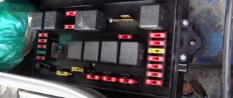
VAZ2112 fuses and relays
- F1 5 License plate lamps. Instrument lighting lamps. Side light indicator lamp. Trunk light. Left side marker lamps
- F2 7.5 Left headlight (low beam)
- F3 10 Left headlight (high beam)
- F4 10 Right fog lamp
- F5 30 Electric door window motors
- F6 15 Portable lamp
- F7 20 Electric motor of the engine cooling system fan. Sound signal
- F8 20 Rear window heating element. Relay (contacts) for turning on the heated rear window
- F9 20 Recirculation valve. Windshield and headlight cleaners and washers. Relay (coil) for turning on the rear window heating
- F10 20 Reserve
- F11 5 Right side marker lamps
- F12 7.5 Right headlight (low beam)
- F13 10 Right headlight (high beam). High beam warning lamp
- F14 10 Left fog lamp
- F15 20 Electric seat heating. Trunk lock lock
- F16 10 Relay-breaker for direction indicators and hazard warning lights (in emergency mode). Hazard warning lamp
- F17 7.5 Interior lighting lamp. Individual backlight lamp. Ignition switch illumination lamp. Brake light bulbs. Clock (or trip computer)
- F18 25 Glove box lighting lamp. Heater controller. Cigarette lighter
- F19 10 Door locking. Relay for monitoring the health of brake light lamps and side lights. Direction indicators with warning lamps. Reversing lamps. Generator excitation winding. On-board control system display unit. Instrument cluster. Clock (or trip computer)
- F20 7.5 Rear fog lamps VAZ-2112.
- K1 – lamp health monitoring relay;
- K2 – windshield wiper relay;
- K3 – relay-interrupter for direction indicators and hazard warning lights;
- K4 – headlight low beam relay;
- K5 – headlight high beam relay;
- K6 – additional relay;
- K7 – relay for turning on the heated rear window;
- K8 – backup car relay.
Information that a motorist must know before replacing existing wiring
First of all, the car owner must know when and in what cases the car wiring is replaced. At the same time, it is also necessary to have information about the final operational life in order to objectively understand when the wiring may need to be replaced. List of the most common reasons that cause wiring to malfunction:
Components needed to perform wiring replacement:
A practical look at rewiring
So, a detailed step-by-step algorithm for replacing the wiring:
Note. Before disconnecting all electronic devices, it is necessary to draw your own conventional electrical circuit by hand in order to correctly make the appropriate connections in the future.
Note. Before you begin the wiring replacement procedure, you need to find its current diagram. Otherwise, during the process of assembly and disassembly, you can quickly get confused, and you will have to send the car to a car service center.
The main advantages of the new wiring:
It is always necessary to remember that installing homemade wiring is an easily feasible technical manipulation; the main thing is to understand all the necessary nuances.
The main objective signs of a car wiring fault
Note. If the essence of the malfunction lies in the ignition system, then one of the diagnostic signs is that the car will not start. Moreover, if the car starts poorly, but still starts, then problems with the wiring can be excluded from the list of possible causes.
Practical example of wiring fault:
The instructions for replacing the wiring yourself are extremely simple, and the diagnostic process, in principle, does not present any significant practical difficulty. It is recommended to use photo and video materials during the replacement process. The main thing is to find the root cause of the problem in the wiring system. It is never too late to modernize VAZ wiring, and this, in turn, will allow you to use almost any modern high-tech devices for your car. The price of replacing the wiring yourself is significantly lower than the corresponding service at a car service center.
Wiring in a car plays one of the most significant roles, since it is actually the connecting link of many functional elements of the car. In the VAZ 2110, wiring is replaced if it malfunctions, or if the owner decides to upgrade. This, in turn, will help to significantly improve the efficiency of the vehicle's electronic systems. Often, old wiring simply cannot withstand the load of various additional high-tech devices. Replacing the wiring in a VAZ 2110 can be easily done on your own.
Information that a motorist must know before replacing existing wiring
Replacing wiring VAZ 2110
First of all, the car owner must know when and in what cases the car wiring is replaced. At the same time, it is also necessary to have information about the final operational life in order to objectively understand when the wiring may need to be replaced. List of the most common reasons that cause wiring to malfunction:
Components needed to perform wiring replacement:
A practical look at rewiring
Replacing wiring on a VAZ 2110
So, a detailed step-by-step algorithm for replacing the wiring:
Note. Before disconnecting all electronic devices, it is necessary to draw your own conventional electrical circuit by hand in order to correctly make the appropriate connections in the future.
Note. Before you begin the wiring replacement procedure, you need to find its current diagram. Otherwise, during the process of assembly and disassembly, you can quickly get confused, and you will have to send the car to a car service center.
Electrical diagram for VAZ 2110
General information
The car and electricity are fused together from the very beginning. You may recall that the very first such vehicle used an electric motor, until the internal combustion engine was invented.
Wiring a VAZ 2112 makes it possible to perform actions that simply cannot be carried out without electricity.
Among them are:
Schematic diagram of the electrical wiring of a VAZ 2112 car (16 valve) In addition, the wiring diagram of the VAZ 2112 will help you figure out how and what the auxiliary equipment is connected to:
The electrical wiring of the VAZ 2112 connects electrical appliances and devices with current sources located in the car. An electrical equipment system is a collection of current consumers and its producers .
Serviced battery
Car power supplies and ignition
Let's take a closer look at it, starting with the most important elements:
A rechargeable battery is a chemical source of energy, which is a lead-acid DC battery module. The photo shows a battery being serviced. Usually there are six of them.
It is used for:
Generator . Used as the main source of current for all electronic and electrical devices and instruments in the car. But, it can provide this only at medium or high crankshaft speeds. The price of this equipment depends on the manufacturer.
Ignition system . Designed to ignite fuel in engine cylinders. Can be contact or non-contact. Modern VAZ 2112 cars are equipped with the latter version, which has a number of advantages over the contact system, which is already considered obsolete.
The main advantages should be noted:
Starter relay installation diagram
If the battery is not charging
When the battery is no longer charged, it does not allow the car to be used for a long time. Maximum until it is completely discharged. In this case, a red light comes on on the instrument panel, which signals that the wiring on the VAZ 2112 requires checking.
The instructions below will help with this:
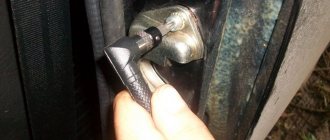
Advice: it is not recommended to apply too much tension; it will significantly shorten the life of the belt.
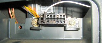
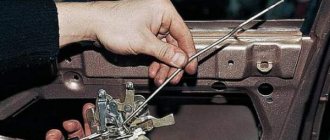
Checking and replacing the fuse
It should not be broken or have oxidized contacts . It happens that there is no way to fix the breakdown, which means that the generator itself needs to be repaired. Repairs must not be delayed as a short circuit may occur. But it’s better to do this at a service station or at home in the garage with your own hands.
Advice: when driving only on battery power, to reduce on-board electricity consumption, turn off as many devices as possible - radio, heater fan, etc.