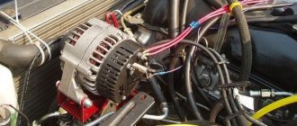
Transfer case location and functions
Location of the transfer case in the Niva 21213
The transfer case occupies an intermediate position in the vehicle transmission between the gearbox and the driveshaft. It has its own body in which its components are located.
The transfer case helps to implement such SUV capabilities as:
- Center differential lock.
- Disabling the drive axle.
- Increased torque of the drive wheels.
- Distribution of torque along the wheel axles.
Transfer case Niva 21213
Model VAZ-21213 is an all-terrain passenger car with permanent all-wheel drive and differential lock. Brand 21213 is a restyled version of the first VAZ SUV, VAZ-2121. RK Niva 21213 has three gears:
- the first - with a gear ratio of 1.2;
- the second, lowered – with the number 2.135;
- neutral
21213 is equipped with 4-speed and 5-speed gearboxes, and when the first speed of the transfer case is turned on, the car operates in standard mode, the gear ratios in the transmission are from 5-speed. The checkpoints are as follows:
- 1 – 4,4;
- 2 – 2,52;
- 3 – 1,63;
- 4 – 1,2;
- 5 – 0,98.
When you turn on the second position of the transfer case lever (reverse position), the gear ratios change (lower):
- 1 – 7,83;
- 2 –4,48;
- 3 – 2,90;
- 4 – 2,14;
- 5 – 1,75.
On ordinary roads, the transfer case is always in first gear, the transfer case control lever (reduction gear) is pushed forward. The neutral gear of the RK disconnects the transmission, and in this position the car does not drive; there is also a neutral in the gearbox.
Motorists often ask the question: why is neutral gear needed in a transfer case? The neutral is used when connecting additional units to the transmission, for example, a mechanical winch; in this case, a power take-off must also be installed.
A series of downshifts
You can often encounter the following type of misconception: switching the rear handle can increase the power characteristics of the motor. But this is not true. It serves to change the gear ratio between the engine and the wheels. By increasing it, the traction forces on the wheels will increase. There is also a reduction gear in the dispensing mechanism.
DON'T SPEND MONEY ON REPAINTING! Now you can remove any scratch from the body of your car in just 5 seconds.
Its operation can be controlled using the rear handle. When we shift the lever back, we will have a gear ratio of 2.135 - this is a low gear. It is recommended to downshift such a gear only when the car is stationary and the clutch is depressed. Despite the fact that the manual does not contain such a restriction, novice and inexperienced Niva drivers are not recommended to switch while driving, since the Niva transfer mechanism is not equipped with a synchronizer.
The device of the VAZ Niva transfer case
The transfer case is not present in all VAZ passenger cars, but only on cars with two drive axles. In the transmission, the transfer case (TC) is installed at the rear of the gearbox; a rear driveshaft is attached to its shank, which connects the transfer case to the rear axle. The front axle is also driven by the steering wheel; it is connected to the transfer case by a front driveshaft.
The reduction gear in the Republic of Kazakhstan is designed to obtain high torque, it is used to overcome difficult sections of the road, and helps to cope with off-road conditions. The VAZ Niva transfer case contains the following main parts:
- the body itself;
- front axle drive shaft;
- intermediate shaft;
- drive shaft;
- gears;
- bearings;
- differential housing;
- satellites;
- differential lock clutch;
- gear shift clutch;
- flanges (for connection to cardan shafts);
- oil seals;
- control levers.
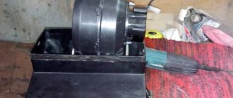
Lowered transfer case on the field
Change of low gear ratio from 2.1 to 2.95. I started with the selection of spare parts, because the 2003 car has a fine-module RC with DS, it was purchased: a 32\42 fine-module intermediate shaft, an old-style 42-tooth differential gear (a terrible shortage), 3rd gear gear 2101, a set of gaskets , oil seals, break-in oil.
I found a source of turning 200 meters from the garage in the form of lathes and grinders with competent guys who don’t need to explain that they need to adjust the tailstock and so on. I gave it a wash, after 2 hours it was ready, it needs to be sharpened until
75.3 mm is then ground to a 75.03 mm fit, the large low gear gear must be ground off the shaft, plus chamfered for welding.
Something like this comes out:
Next, for experiments, so that the machine was always on the move, because it was working, a small-modular used RK with a DS of the year 2000 was purchased, completely disassembled, and the following actions were performed.
The differential is given for grinding, on the opposite side of the gear it is ground down to 76.5x14 mm, 2 windows open into the differential, it’s hard to see in the photo:
The body is sharpened so that it can be assembled with a new shaft, it must be sharpened from below:
The bushing is pressed off the drive shaft and the low gear is removed, replaced with the 3rd gear and assembled, it fits without modifications.
Did you warm up the new shaft gear on a gas stove? but not like locking rings (not to the color of the first tarnish), they must be put on flush with the inner surface of the turned part. That is, the gear should protrude outward from the side of the bearing, it does not interfere with it. Afterwards, I welded it with manual DC welding using MP 2 mm electrodes. First, I grabbed it with dots in a circle, then with a seam at a time from opposite sides, letting it cool, then I grinded it. Assembled with bearing:
Next, we assemble the whole thing in the RK and turn it, observing the scratching of the body or differential, not forgetting that when we screw on the covers, the stoppers will move the bearings and shafts deeper into the body.
After final assembly, I twisted the drill for several minutes.
I express my deep gratitude to DEN_NIVA for opening my eyes to the features of the design; previously, a similar design was offered on the French website, but there it was proposed to grind the differential gear, the fit of the gear on the shaft can be calculated and used only hot without welding. I don’t have an indicator, so before welding I tried to determine the runout by placing a ruler at the end and stretching a 0.12 mm feeler gauge between the ruler and the end of the machined gear, the runout is apparently less than 0.02mm. I didn’t bother with the calculation and execution of the hot fit, but perhaps in vain, the welding did not produce any noticeable beating, since the noise in all modes does not particularly exceed the noise from a conventional small-module welding machine.
Centering method
To carry out this work you will need a lift, although with some skill you can get by with simple supports. First you need to prepare the car. If there is a lift, it is raised up. If supports are used, the corners of the machine are jacked up one by one and it is placed on them. Please note that all supports must be stable, otherwise the work will be unsafe. You should also prepare the tool in advance. If there are no plans to simultaneously replace other parts, then it is quite possible to get by with a ratchet and a “13” head. During operation, an assistant must be in the cabin.
Adjustments are made in the following order:
- To begin with, you should evaluate the condition of the splines on the cardans. If they are very worn, then most likely you will not be able to perform the alignment correctly. In case of significant wear, parts should be replaced;
- The transfer case mount is inspected. Often the displacement can be seen with the naked eye;
- Next, loosen the transfer case mount. Just don’t unscrew it completely;
- After this, start the engine and “accelerate” the car to a speed of 80-90 km/h. In this case, the transfer case will fall into place on its own;
- The crucial point is to consolidate the result obtained. This can be achieved in 2 ways. Mechanics argue which one is better, but both are used in everyday life. Most often, the engine is turned off, and with its help the transfer case and cardan shafts are stopped.
- All that remains is to quickly tighten the nuts. Disadvantage here 2. Stopping the box in this way can have a negative impact on its condition.
- Also, you need to tighten the fastener as quickly as possible, otherwise it will be of no use. A more reliable, but technically complex method is to tighten with the engine running;
- The car is lowered to the ground and testing is performed.
If the vibration persists, the procedure should be repeated.
Eliminating prerequisites
The misalignment of the transfer case occurs due to an undeveloped design. Therefore, many craftsmen strive to modify the fastening so as not to bother with alignment once a year. A special frame is used for this. In recent years, it can be purchased in stores, but you can also make it yourself. The advantages of this modification are the following:
- The transfer case is mounted on the rigid base of the subframe. The attachment to the body is made through a subframe, this allows to reduce the level of vibration transmitted to the body;
- It plays the role of a kind of protection for the crankcase;
- Also worth mentioning is adding additional rigidity to the side members.
- Among the disadvantages, we can mention a slight decrease in clearance. Although, in light of the advantages, this does not play a special role.
To assemble the subframe you will need a square pipe. Some people use a corner, but in this case the structure will be less durable. The support plates are made of sheet steel. Before assembly, you should cut off the old transfer case mounting bolts. Now it will be installed on the subframe. The pipe is cut to size and the frame is welded. After that, holes are drilled in the crossbars for fastening the transfer case. It is important not to make a mistake with the sizes. The next step will be assembling the mount to the body. Sheet steel support plates are welded to the subframe. Holes are drilled in it. After fitting, you need to drill holes in the floor of the car.
M12 bolts should be used for fastening
, as well as thick washers.
After installing the subframe, do not forget to treat it with an anti-corrosion compound. This will increase the service life of the part. This is how, through simple manipulations, you can get rid of one of Niva’s sores. Conclusion
. Even great cars have flaws. The domestic SUV Niva is no exception. During active use, vibrations emanating from the transmission may occur. That’s when the question arises of how to center the transfer case on the Niva. In fact, this work is not difficult, but there are some nuances that are better to know before starting work. Some people, knowing this feature of this car, install a subframe, this can significantly reduce the noise of the transmission.
Homemade design
Many people make a similar subframe for the Niva on their own. First you need to make a drawing of the subframe. The simplest design consists of two crossbars and two crossbars connecting them.
The distance between the crossbars should be exactly the same as the distance between the transfer case attachment points to the bottom. Holes are made in the crossbars themselves to which the transfer case will be attached. To strengthen the structure, you can weld braces from metal corners in the inner corners between the crossbars and crossbars.
This design will be attached not to the bottom, but to the side members, so their length must correspond to the distance between the side members. Having made a drawing, you can create this device on the Niva with your own hands. Depending on the wishes of the owner, it can be made collapsible, bolted.
The advantage of such a subframe is the ability to replace a damaged element without removing the entire structure from the car. The disadvantage will be the need to constantly monitor the condition of the bolted connection. The welded structure of the subframe does not require constant monitoring, but if damaged, it will have to be completely replaced.
Next, you need to decide how the subframe under the transfer case will be attached to the side members. It is possible to attach it to the side surface of the subframe. To do this, you will need to drill through holes in the side surface at the mounting points.
The advantage of fixing it to the side surface of the spar is the ability to additionally install silent blocks at the fastening points, which will further dampen vibrations coming from the transfer case. The downside is the need to carry out additional calculations of the diameter of the bolts with which the structure will be attached to the spar, since in this case they will be subject to shear force. A bolt with a diameter that is too small will likely fail quickly due to vibration.
Niva transfer case. Ways to eliminate vibration
The Niva family of cars differs from VAZ passenger cars in permanent all-wheel drive - they have two drive axles. In total, the VAZ SUV has three differentials in its transmission - one for each axle and another center differential.
1. Oil seal; 2. Thrust ring of the front bearing of the drive shaft; 3. Front bearing cover; 4. Front drive shaft bearing; 5. Transfer case front cover; 6. High gear; 7. Gear clutch hub; 8. Gear clutch; 9. Low gear; 10. Transfer case housing; 11. Rear drive shaft bearing; 12. Drive shaft; 13. Transfer case rear cover; 14. Intermediate shaft; 15. Rear intermediate shaft bearing; 16. Rear differential housing bearing; 17. Installation ring of the rear axle drive shaft bearing; 18. Rear axle drive shaft bearing; 19. Oil seal deflector; 20. Rear axle drive shaft flange; 21. Rear axle drive shaft; 22. Bearing thrust ring; 23. Differential housing; 24. Rear axle drive gear; 25. Satellite; 26. Axle of satellites; 27. Retaining ring of the satellite axis; 28. Spring washer; 29. Driven gear; 30. Differential housing bearing retaining ring; 31. Differential locking clutch; 32. Front axle drive shaft; 33. Front axle drive housing; 34. Retaining ring of the front axle drive shaft bearing; 35. Differential bearing spring washer; 36. Front differential housing bearing; 37. Driven gear of the speedometer drive; 38. Speedometer drive housing; 39. Front intermediate shaft bearing; 40. Gearbox; 41. Elastic coupling; 42. Constant velocity joint; 43. Transfer case; 44. Shims; 45. Transfer case suspension bracket; 46. Rear engine mount bracket.
Eliminate vibration with additional fasteners
Installing the third support of the transfer case on VAZ 21213/21214 vehicles allows you to reduce the level of vibration of the transfer case; with this support it is easier to center the transfer case. The part can be purchased at auto stores or made yourself. The finished product comes with three long studs (for model 2121); to install the third support on this machine, you will need to unscrew the short studs from the transfer case housing and install new studs from the kit. We carry out repairs as follows:
- dismantle the front passenger seat in the cabin;
- remove the floor tunnel lining;
- in the cabin we move aside the carpet covering the body amplifier (in front of the handbrake lever);
- remove the transfer case (alternatively, you can simply hang it up, but removing the third support makes it easier to install);
- We attach the bracket of the new support to the body of the RC;
- we install the transfer case in place, center it in the optimal position, and fasten the side supports;
- we combine the third support with the body, drill two holes in the bottom;
- Using washers, bolts and nuts (from the kit) we attach the support to the bottom of the body.
Vibration is eliminated more effectively by installing a subframe under the transfer case. You can also make such a device yourself or buy a finished product at a car store.
In order to install the subframe, the transfer case must be removed. It is more convenient to carry out such work in a pit; we carry out repairs as follows:
- leave the car in neutral gear;
- disconnect the propeller shaft from the transfer case, it is advisable to mark the driveshaft flange and the drive shaft so that during installation, align the driveshaft according to the marks - this way, the occurrence of unnecessary vibrations is eliminated;
- dismantle the muffler mounting bracket;
- remove the gearbox traverse;
- jack up the transfer case, remove the side fastenings of the transfer case;
- We treat the places where the subframe fits to the body with Movil;
- place the subframe on the gearbox studs;
- we mark the attachment points of the subframe on the side members, drill holes, attach bolts to the body;
- we tighten all fastenings, except for the transfer case supports themselves;
- we perform alignment of the steering wheel;
- Finally tighten the transfer case supports.
It should be noted that installing an additional support or subframe on the steering wheel does not always lead to the desired effect; in some cases, vibration only increases.
Installation of subframe step by step video
Video 2 off-road rides
For all its popularity, the Niva 2121 has a number of disadvantages. One of the most common problems with this SUV is increased vibration in the cabin. Moreover, the more the car is used, the more noticeable the vibration becomes.
The reason for the increased vibration is a structurally incorrect solution for securing the transfer case (transfer case). The fact is that this box on the Niva is attached directly to the bottom using silent blocks. And since during operation the vibration of the transfer case is significant, all this is transmitted to the cabin.
As a result, strong vibration affects the transmission and it wears out faster. Although the metal of the bottom in the area where the transfer case is attached is reinforced, due to strong vibration, the bottom is destroyed over time due to exposure to vibration.
Often, Niva 2121 owners, in order to reduce vibration in the cabin, install a subframe under the transfer case. This device is made of metal. The Niva subframe absorbs any vibration impact from the transfer case.
The subframe has enough advantages:
- Receives the oscillatory movements of the transfer case.
- Protects its body from possible damage when driving off-road.
- When installed correctly, there is virtually no displacement of the axis between the transfer case and the gearbox, which has a positive effect on the durability of both transmission units, as well as cardan and intermediate shafts.
We study problems and repair methods.
Any car owner definitely doesn’t need to be told why howling and humming are bad. Vibration of the transfer case on a Niva at low speed is quite common. The driver, of course, gradually gets used to many extraneous sounds in the car, but the noise level is high enough to make it impossible to carry on a conversation with passengers while traveling. Due to excessive noise pollution, you will inevitably have to deal with the problem.
Sources
- https://motorltd.ru/snyatie-i-tsentrirovanie-razdatochnoy-korobki-vaz/
- https://www.vazzz.ru/vaz-21213-razdatka-ustrojstvo-shema-tsentrovka-snyatie/
- https://avto-idea.ru/remont/remont-razdatki-na-nive-21213-kak-ottsentrovat/
- https://AutoFlit.ru/2260-kak-otcentrovat-razdatku-na-nive-sposob-dlya-korotysha-i-shevrole.html
- https://NewNiva.ru/kak-ustranit-vibratsiyu-na-nive-21214.html
[collapse]