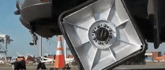
When the car moves, the wheels shift relative to the body, and the trajectory of this displacement is determined by the design of the so-called suspension guide vane, consisting of levers (longitudinal, transverse or diagonal) and joints (ball and rubber-metal). In some suspensions, the element of the guide vane may be anti-roll bars, as well as shock absorber struts (McPherson type). When the elastic element of the suspension is deformed as a result of changes in vehicle loading, overcoming road unevenness, body roll under the influence of centrifugal forces when turning in the suspensions of most designs, the position of the wheel relative to the body changes, and all installation angles change along with it. An exception, perhaps, is suspension with parallelogram trailing arms (used in the front suspension of the ZAZ-965), and even then only in the absence of body roll. However, if we ignore general considerations, we should be guided by the following considerations. Car suspension, along with the car, has been constantly improved for more than a hundred years. Each specific design, before being translated into serial production, goes through a long stage of research and refinement. Therefore, the recommendations of car manufacturers in general and regarding the installation of wheels in particular should be taken with complete seriousness and responsibility.
For those who want to understand what Wheel Alignment Angles (Camber/Toe) mean and thoroughly understand the issue, this article has answers to all questions.
An excursion into history shows that sophisticated wheel installations were used on various vehicles long before the advent of the automobile. Here are a few more or less well-known examples. It is no secret that the wheels of some carriages and other horse-drawn carriages, intended for “dynamic” driving, were installed with a large, clearly visible positive camber. This was done so that the dirt flying from the wheels did not fall into the carriage and important riders, but was scattered to the sides. For utilitarian carts for leisurely movement, everything was exactly the opposite. Thus, pre-revolutionary manuals on how to build a good cart recommended installing wheels with negative camber. In this case, if the dowel stopping the wheel was lost, it did not immediately jump off the axle. The driver had time to notice the damage to the chassis, which was fraught with especially big troubles if there were several dozen pounds of flour in the cart and there was no jack. In the design of gun carriages (again, vice versa), positive camber was sometimes used. It is clear that it was not intended to protect the gun from dirt. This made it convenient for the servant to roll the gun by the wheels with his hands from the side, without fear of crushing his legs. But the cart’s huge wheels, which made it easy to get over the ditches, were tilted in the other direction - towards the cart. The resulting increase in track helped to increase the stability of the Central Asian “mobile,” which was distinguished by a high center of gravity. What do these historical facts have to do with the installation of wheels on modern cars? Yes, in general, none. However, they provide a useful insight. It can be seen that the installation of wheels (in particular, their camber) is not subject to any single pattern.
You must understand that these recommendations are different for each car model. For example, on some cars zero and even negative camber angles are installed. But in any case, these angles provide the best stability and handling, as well as minimal wear on the tires of a particular car model.
It should be noted that factory recommendations include certain requirements for vehicle loading (curb weight, gross permissible weight, etc.), the technical description and vehicle operating instructions indicate the values of the wheel alignment angles and steering axes, as well as the conditions under which they are checked and installed.
It is useful to monitor them periodically during the operation of the car (at least after 30,000 km), and if individual suspension elements have been replaced on the car, and even more so after serious impacts on the chassis, this simply needs to be done immediately. In any case, it should be remembered that adjusting the camber and toe angles of the steering wheels is the final operation of repairing the suspension, chassis parts and steering of the car, and nothing else. But first, let's understand the theory and remember what wheel installation parameters affect what and why all these angles are needed.
Maximum steering angle
It characterizes the maximum angle at which a car wheel will turn when the steering wheel is fully turned. And the smaller this angle, the greater the accuracy and smoothness of control. After all, to turn even at a small angle, only a small movement of the steering wheel is required. But do not forget that the smaller the maximum turning angle, the smaller the turning radius of the car. Those. It will be very difficult to turn around in a confined space. So manufacturers have to look for some kind of “golden mean”, maneuvering between a large turning radius and control accuracy.
Rolling shoulder
Roll shoulder is the shortest distance between the middle of the tire and the steering axis of the wheel. If the axis of rotation of the wheel and the middle of the wheel coincide, then the value is considered zero. With a negative value, the rotation axis will move outward of the wheel, and with a positive value, it will move inward. For rear-wheel drive vehicles, a run-in shoulder with a zero or negative value is recommended. But in practice, due to the design of the car, this is very difficult to do, because the mechanism does not fit inside the wheel. So the end result is a car with a positive roll-in shoulder, which behaves unpredictably: the steering wheel can be torn out of your hands when driving over uneven surfaces; when driving around corners, a noticeable moment is created that prevents uniform movement. To combat the positive roll shoulder, experts tilted the steering axis in the transverse direction and made a positive camber of the wheels. Although this reduced the car's roll-in leverage, it had a bad effect on the car's control when turning.
Caster angle
Caster is responsible for the dynamic stabilization of the steered wheels. In simple terms, caster makes the car drive straight when the steering wheel is released. Those. If you take your hands off the steering wheel, then the car should ideally drive straight and not deviate anywhere. If a lateral force (for example, wind) acts on the car, then the caster should ensure a very smooth turn of the car in the direction of the force when the steering wheel is released. In addition, the caster prevents the car from tipping over.
Caster angle. The main function of the caster is to tilt the wheels in the direction the car's steering wheel is turning. The inclination of the wheel affects traction and, therefore, the handling of the car. If the car is moving straight, the wheels have the greatest traction, which provides the driver with a quick start and later braking. But in a turn everything is different. When the wheel turns, the tire is deformed under the influence of lateral forces. And in order to maintain the maximum contact patch with the road, the car’s wheel also tilts in the direction of the turn. But everywhere you need to know when to stop, because with a very large caster, the car’s wheel will tilt strongly and then lose traction.
Lateral tilt of the axis of rotation
Responsible for weight stabilization of the steered wheels. The point is that the moment the wheel deviates from “neutral” the front end begins to rise. And since it weighs a lot, when the steering wheel is released under the influence of gravity, the system tends to take its initial position, corresponding to movement in a straight line. True, for this stabilization to work, it is necessary to maintain the (albeit small, but undesirable) positive roll-in shoulder. Initially, the transverse angle of the steering axis was used by engineers to eliminate the shortcomings of the car's suspension. It got rid of such “illnesses” of the car as positive camber and positive rolling shoulder.
Many modern cars use MacPherson type suspension. It makes it possible to obtain a negative or zero rolling leverage. After all, the steering axis of the wheel consists of the support of one single lever, which can easily be placed inside the wheel. But this suspension is not perfect either, because due to its design, it is almost impossible to make the angle of inclination of the turning axis small. When turning, it tilts the outer wheel at an unfavorable angle (like positive camber), while the inner wheel simultaneously leans in the opposite direction. As a result, the contact patch of the outer wheel is greatly reduced. And since the outer wheel bears the main load when turning, the entire axle loses a lot of traction. This, of course, can be partially compensated for by caster and camber. Then the grip of the outer wheel will be good, but the grip of the inner (less important) wheel will practically disappear.
The shoulder of the wheel running in is due to the height of the tires. Positive effect of negative leverage
In the original version of such a suspension, developed by MacPherson himself, the ball joint was located on the extension of the axis of the shock absorber strut - thus, the axis of the shock absorber strut was also the steering axis of the wheel.
Later, for example on the Audi 80 and Volkswagen Passat of the first generations, the ball joint began to be shifted outward towards the wheel, which made it possible to obtain smaller and even negative break-in shoulder values. Thus, the Scrub Radius
- this is the straight line distance between the point at which the wheel's steering axis intersects with the road surface and the center of the contact patch between the wheel and the road (in an unloaded state of the vehicle). When turning, the wheel “rolls” around its axis of rotation along this radius.
It can be zero, positive or negative (all three cases are shown in the illustration).
For decades, most vehicles have used relatively large positive run-in values. This made it possible to reduce the force on the steering wheel when parking compared to a zero roll-in arm (because the wheel rolls when the steering wheel is turned, and does not just turn in place) and free up space in the engine compartment by moving the wheels “outside.”
However, over time, it became clear that a positive rolling shoulder can be dangerous - for example, when the wheels of one side collide with a section of the side of the road that has a different coefficient of adhesion than the main road, the brakes on one side fail, one of the tires punctures, or the steering wheel starts to “tear” badly. out of hand." The same effect is observed with a large positive roll-in shoulder and when driving over any unevenness on the road, but the shoulder was still made small enough so that during normal driving it remains barely noticeable.
Starting from the seventies and eighties, as vehicle speeds increased, and in particular with the spread of MacPherson-type suspension, which easily allowed this from the technical side, cars with zero or even negative rolling shoulder began to appear en masse. This allows us to minimize the dangerous effects described above.
For example, on the “classic” VAZ models, the break-in shoulder was large and positive; on the Niva VAZ-2121, thanks to a more compact brake mechanism with a floating caliper, it was reduced to almost zero (24 mm), and on the front-wheel drive LADA Samara family, the break-in shoulder became narrower negative. Mercedes-Benz generally preferred to have a zero break-in shoulder on its rear-wheel drive models.
The rolling shoulder is determined not only by the suspension design, but also by the wheel parameters. Therefore, when selecting not (according to the terminology accepted in the technical literature, this part is called the “wheel”
and consists of a central part -
the disk
and an outer part on which the tire sits -
the rim
) for the car, the permissible parameters specified by the manufacturer should be observed, especially the offset, since when installing wheels with an incorrectly selected offset, the rolling shoulder can change greatly, which is very significant affects the handling and safety of the vehicle, as well as the durability of its parts.
For example, when installing wheels with zero or negative offset with a positive offset provided from the factory (for example, too wide), the plane of rotation of the wheel shifts outward from the wheel’s rotation axis, which does not change, and the rolling shoulder may acquire an excessively large positive value - the steering wheel begins to “tears out of your hands” on every uneven road, the force on it when parking exceeds all permissible values (due to an increase in the lever arm compared to the standard reach), and wear on the wheel bearings and other suspension components increases significantly.
Many factors depend on proper wheel alignment: handling, tire life, fuel consumption. Let's look at them - what they influence and what they are needed for.
What are they for?
Manufacturers' recommendations for wheel installation should be taken with full responsibility.
The recommendations are different for each model. These angles provide the best stability and handling, as well as minimal tire wear. Periodically, when operating a car (after 30,000 km), it is useful to monitor them, and if individual suspension elements have been replaced on the car, and especially after serious impacts, this must be done immediately. It should be remembered that adjusting the steering wheel angles is the final operation of suspension repair.
, chassis and steering parts.
Maximum rotation angle
Characterizes the maximum angle at which a car wheel will turn when the steering wheel is fully turned.
The smaller it is, the greater the accuracy and smoothness of control. After all, to turn even a small angle, only a small movement of the steering wheel is required. Do not forget that the smaller the maximum turning angle, the smaller the turning radius of the car. Those. It will be difficult to turn around in a confined space. You have to maneuver between a large turning radius and control accuracy.
Rolling shoulder
This is the shortest distance between the middle of the tire and the steering axis of the wheel.
If the axis of rotation and the middle of the wheel coincide, then the value is considered zero. With a negative value, the rotation axis moves outward of the wheel, and with a positive value, it moves inward.
For rear-wheel drive vehicles, a run-in shoulder with a zero or negative value is recommended. In practice, due to the design of the machine, this is difficult to do, because the mechanism does not fit inside the wheel. The result is a car with a positive rolling shoulder, which behaves unpredictably: the steering wheel can be torn out of your hands when driving over uneven surfaces; when cornering, a noticeable moment is created that prevents uniform movement.
To combat the positive roll shoulder, experts tilted the steering axis in the transverse direction and made positive camber. Although this reduced the roll-in shoulder, it had a bad effect on car control when turning.
Caster angle
Responsible for dynamic stabilization of the steered wheels. Simply put, it makes the car go straight when the steering wheel is released.
Those. If you take your hands off the steering wheel, then the car should ideally drive straight and not deviate anywhere. If a lateral force (for example, wind) acts on the car, then the caster should ensure a smooth turn of the car in the direction of the force when the steering wheel is released. In addition, the caster prevents the car from tipping over.
The main function of the caster is to tilt the wheels in the direction the steering wheel is turning. The inclination of the wheel affects traction and therefore controllability. If the car moves straight, the wheels have the greatest traction, which provides the driver with a quick start and later braking.
When the wheel turns, the tire is deformed under the influence of lateral forces. To maintain maximum contact patch with the road, the wheel also tilts in the direction of the turn. But you need to know when to stop, because with a large caster, the wheel will tilt strongly and then lose traction.
Lateral axis tilt
Responsible for weight stabilization of the steered wheels.
The point is that the moment the wheel deviates from “neutral” the front end begins to rise. And because It weighs a lot, then when you release the steering wheel under the influence of gravity, the system tends to take the initial position corresponding to movement in a straight line. True, for this stabilization to work, it is necessary to maintain the (albeit small, but undesirable) positive roll-in shoulder.
Initially, the transverse angle of the steering axis was used by engineers to eliminate the shortcomings of the car's suspension. It got rid of such “illnesses” as positive camber and roll-in shoulder.
Many cars use MacPherson-type suspension. It makes it possible to obtain a negative or zero rolling leverage. After all, the steering axis consists of the support of one single lever, which can be placed inside the wheel. This suspension is not perfect, because it is almost impossible to make the axle angle small. When turning, it tilts the outer wheel at an unfavorable angle (like positive camber), while the inner wheel simultaneously leans in the opposite direction.
As a result, the contact patch of the outer wheel is greatly reduced. Because the outer wheel bears the main load when turning, and the entire axle loses a lot of grip. This, of course, can be partially compensated for by caster and camber. Then the grip of the outer wheel will be good, but that of the inner wheel will practically disappear.
Wheel alignment
There are two types of convergence: positive and negative.
It’s easy to determine: you need to draw two straight lines along the wheels of the car. If these lines intersect at the front of the car, then the toe is positive, and if at the rear, it is negative. If the toe-in is positive, then the car turns easier, and will also gain additional steering, and will be more stable when driving straight. If the toe-in is negative, then the car drives inadequately, scouring from side to side. But it should be remembered that excessive deviation of the toe from the zero value will increase rolling resistance during straight-line movement; in corners this will be less noticeable.
Wheel camber
It can be negative and positive.
If you look from the front of the car and the wheels tilt inward, this is negative camber. If they deviate outward - positive. Camber is necessary to maintain traction between the wheel and the road surface. On production cars they have zero or slightly positive camber. If you need good controllability, it is made negative.
Rear wheel adjustment
Many cars do not adjust the angles of the rear wheels.
For example, on front-wheel drive VAZ cars, where a rigid beam is installed at the rear. Violations can only occur in the event of a serious accident, when the rear beam bends. Also, the rear angles are not adjustable on SUVs with a rigid axle. Many foreign cars have a multi-link suspension at the rear. This means that you can adjust the toe-in and camber of the rear wheels. This must be done after hitting a curb or an accident. Because any car is very sensitive to changes in the toe angle of the rear wheels. If it is negative, the car will constantly skid when cornering. If it’s positive, that’s also bad, the car will experience understeer. When turning, the car will tend to go straight.
What to do first?
First, the angles of the rear wheels are adjusted (it is possible), and only then the front wheels.
First they set the caster, then the camber and last (mandatory) the toe. You also need to make sure that the steering wheel is straight. To do this, use special devices to fix it. We also note that using sport settings will have a negative impact on comfort. If you make the caster too high or have too much negative camber, the steering force will increase. But this is the best way to change the car's behavior to a more sporty one.
The driver drives the car. There is an obstacle ahead. It slows down, but the brakes “take” slightly differently. In most cases, this difference is practically unnoticeable. But when braking very sharply (Fig. 1), the car throws to the side, maybe only half a meter, or skids and... an accident. It also often occurs due to the fact that when braking, the wheels of one side of the car end up on ice, mud or water.
What do these cases have in common? The general thing is that the wheels of the right and left sides were in different conditions in terms of the forces of resistance to movement. And, naturally, these different conditions “provoked” a skid or spontaneous turn of the car, which the driver did not always have time to correct in time.
“Self-defense” against skidding
All modern models necessarily have two independent circuits in the hydraulic brake drive (see). To ensure that braking efficiency is maintained, and therefore safety, it is necessary that the brake of at least one front wheel be activated in case of any malfunction. For this reason, the cheapest and simplest of the dual-circuit ones, the diagonal circuit of a separate hydraulic brake drive, has become widespread. But the transition to it forced the designers to include “self-defense measures” in the geometric relationships of the parameters of the front suspension and steering drive. This measure is a negative running-in leverage.
A few words about the term itself. The break-in shoulder (Fig. 2) is the distance between point G of the tire contact with the road and point B. It marks the intersection with the road of the extension of the imaginary axis passing through the centers of the upper and lower ball joints of the double-wishbone front suspension. If the GW segment is located inside the vehicle track (Fig. 2a), it is considered positive. If, due to a certain combination of sizes of parts in the front suspension, the section of the main suspension ends up outside the track, then the running shoulder r is considered negative (Fig. 2b).
Now let's see what happens when braking a car with a diagonal separate hydraulic brake drive circuit. Let's assume that one of the circuits (say, serving the brakes of the front right and rear left wheels) has failed. When you press the pedal, the front left and rear right wheels are braked (Fig. 3). At the points of their contact with the road, braking forces arise, Ftp and Ftz, respectively.
The moment from the inertia force Fn applied at the center of gravity of the car's CG on a shoulder equal to half the track will begin to turn the car around the front left wheel. It will only be neutralized to a small extent by the moment from the force Fts, turning the car in the opposite direction around the braked rear right wheel. Let us separately consider the power of Ftp. It is significantly larger than Ftz (due to the redistribution of the adhesion weight during braking), therefore, to simplify the diagram of the action of forces, we will conventionally assume that only one front wheel is braking, and the inertial force turns the car around it. But the same situation arises in any scheme, and even if the drive is fully operational, but when braking, the wheels of one side of the car hit a surface with a low coefficient of adhesion (ice, snow, wet) or in the event of a tire rupture on one of the front wheels while driving. Maintaining the given direction is very difficult, and sometimes impossible. In addition, here the steered wheels tend to turn in the direction where the braking force can be realized due to a higher coefficient of adhesion, sharply increasing the vehicle's turn.
Let's turn to Fig. 4. When braking, the steered wheel rotates relative to the “pivot”, the imaginary axis AB, under the action of the braking force Ftp.
Steering effort reduced to almost zero
With a traditional, positive rolling arm (segment GV in Fig. 4a), a moment Mm arises, acting in the same direction as the moment Mi, formed by the inertia force Fn on an arm equal to half the track.
If we design the suspension of the front wheels so that the running-in arm turns out to be negative (segment VG in Fig. 4b), then the product of this arm by the force Ftp applied at the point of contact G of the wheel with the road will give a moment Mt acting in the direction opposite to the moment Mi , and will neutralize it.
During comparative tests of cars with negative and positive run-in shoulders, braking was carried out from an initial speed of 80 km/h in the absence of wheel locking and the steering wheel was released. One of the circuits of the diagonal drive circuit was artificially switched off. For the model with a positive break-in arm, the rotation angle relative to the original direction of movement was 140-160° with a significant lateral displacement. And the model with a negative running arm built into the design had a rotation angle within 15-17°, that is, it practically did not deviate from the original trajectory. This is clear evidence of the undoubted advantage of a negative run-in shoulder during asymmetrical braking of a car.
Particularly interesting in this regard are the test data obtained on the amount of force or torque that the driver must apply to the steering wheel in order to keep the car on the desired trajectory when braking. The torque on the steering wheel required for this with a positive break-in arm reaches approximately 130 kgf*cm, that is, with a steering wheel radius of 20-25 cm, the driver must apply a force of more than 5-6 kgf. On a car with a negative run-in shoulder, the torque on the steering wheel under the same conditions is negligible and fluctuates around zero. At the same time, adjusting the steering trajectory does not cause any difficulties for the driver.
Skid when braking – 10 times less
This is the positive effect of a negative run-in shoulder, which increases safety by maintaining a straight trajectory when braking or when the wheels of one side hit a slippery section of the road.
How big can the negative run-in shoulder be? If its value is too large, it can lead to a deterioration in the stabilizing properties of the steering, which will have to be compensated by correspondingly increasing the longitudinal inclination of the king pin. But such “compensation”, in turn, will increase the force on the steering wheel, which is undesirable. Therefore, for most cars, the value of the negative run-in shoulder ranges from 2 to 10 mm, reaching 18 mm in extreme cases (as done on the Audi 80). The other extreme is models with a break-in shoulder equal to zero (Mercedes-Benz).
When you're tinkering with a repair, experimenting with wheel sizes, or tuning a newly installed suspension, an embarrassment may occur that you may have never even heard of - it's likely that the radius of the break-in shoulder will change. This "thing" can have a serious impact on the handling of your car.
Without a clear and complete understanding of all the factors that affect suspension performance, wheel alignment and geometry, it's easy to make tuning mistakes that end up making your car feel worse than before. At the same time, it is quite difficult to catch the moment when an unfortunate mistake was made.
In general terms, the radius of the running shoulder
is an elusive, almost mythical setting that sits somewhere on the edge of key adjustments such as camber, offset and wheel size. Essentially, it is determined by the location of the point in space where an imaginary line passing through the center of the suspension intersects a vertical line passing through the center of the wheel, these two lines will meet somewhere. It is important that this angle is calculated with the car without load. This is extremely important for calculations carried out by engineers.
Note the larger suspension angle relative to the wheel
In general, there are three main options for shoulder radius:
If the two lines intersect exactly at the tire contact patch, the vehicle does not have a break-in radius.
If the lines intersect below the contact patch, theoretically underground, then this is called a positive running shoulder radius.
When both lines converge above the contact patch, this is a negative run-in shoulder.
Depending on these settings, they can have a major impact on how the car handles, accelerates and stops. Different axle load designs and drive configurations require different settings, which will be calculated long before engineers begin implementing the desired handling characteristics. Yes, automakers have a lot of difficult work to do, and this stage is just one of them. Change just one parameter in the suspension and you initiate a chain reaction that can ultimately defeat your main goal.
Running shoulder radius refers to the relative angle between the suspension and the wheel axle
At zero radius, a common belief is that this setting can make the car feel slightly unstable at the front end when cornering and under hard braking.
On the other hand, when stationary, when turning the steering wheel, you have to turn the contact patch, which is spread out as much as possible on the road surface, which requires more effort and wears out the tire more. This type of setup (zero leverage) is extremely rare on cars these days. A little more or a little less, but not zero.
You can, of course, change the zero setting. For example, "pull out" the wheels with spacers or install fully adjustable coilovers and the radius can become positive. This will cause the tire to scrape the ground when cornering, adding uneven wear and reducing tire life. A car with a positive break-in shoulder can behave unpredictably on the road: the steering wheel can be pulled out of your hands when driving over bumps, and when driving around corners, a “palpable moment is created that prevents uniform movement.”
The positive aspect of this setting exists for rear-wheel drive cars. They find this setting useful to help keep the front wheels pointed straight even when you let go of the steering wheel. Used in sports cars and comes standard with most double wishbone suspension designs.
Volkswagen Scirocco front axle
A positive shoulder radius does not contribute to braking if, for any reason, there is a difference in force between the sides of the vehicle. For example, if the left wheels have less traction and the ABS system does not allow them to develop maximum force. In this case, the car will try to turn towards the wheels with more grip.
Extreme positive shoulder radius can be very severe, so much so that it was only really viable on older cars with very thin tires.
Most of us have a negative shoulder radius on our cars because it tends to go hand in hand with the MacPherson strut settings. This helps the steered front wheels feel more stable on the road, which is good for cornering and the overall handling of the car if, say, one of your front tires suddenly goes flat. Another handy "side effect" is that if you hit the water on one side of the car, the negative radius will work against the car's natural drift, mitigating the impact of going through the dangerous part.
Negative shoulder radius is safer when hydroplaning
Setting the suspension to negative leverage is the safest way to do this. It (the setting) allows you to generate certain forces that will reduce any unintentional tendency by the driver to change the direction of movement, which in the case of a positive setting may occur.
Mikhail's note revealed some questions regarding the adjustment of the steering wheel angles.
Together we will try to figure it out.
Camber
(camber)—reflects the orientation of the wheel relative to the vertical and is defined as the angle between the vertical and the plane of rotation of the wheel.
F1 cars have negative camber
Convergence
(TOE) - characterizes the orientation of the wheels relative to the longitudinal axis of the vehicle.
It is believed that the influence of negative camber needs to be compensated by negative toe-in and vice versa, due to the deformation of the tire in the contact patch, the “cambered” wheel can be represented as the base of a cone.
The picture shows positive camber and positive toe.
One of the positive aspects of negative toe-in is increased steering response.
In addition to camber and toe, which can be seen with the eye, there are several other parameters that affect the car’s handling.
Rolling shoulder
- one of the parameters that affects the sensitivity of the steering.
Thanks to it, the steering wheel “signals” about a violation of the equality of longitudinal reactions on the steered wheels (uneven surfaces, uneven distribution of braking forces between the right and left wheels).
Positive (a) and negative (6) rolling arm: A, B - centers of the ball joints of the front suspension; B is the point of intersection of the conventional axis, the “pivot,” with the road surface; G - the middle of the tire contact patch with the road.
The rolling shoulder does not affect the ease of steering. In the presence of a rolling shoulder, the longitudinal forces acting on the steered wheels create moments that tend to turn them around the turning axis. But in the case of equal forces on both wheels, the moments turn out to be “mirror”, i.e. equal and opposite directions. Mutually compensating for each other, they do not affect the steering wheel. However, the moments load the parts of the steering linkage with tensile or compressive (depending on the location of the rolling arm) forces.
(Negative camber increases the positive value of the rolling arm)
Weight stabilization of the front wheels.
When the wheel turns, the front part of the car rises, so under the influence of weight the wheel tends to take a position of linear movement. Weight, or static, stabilization of the front wheels (i.e., ensuring their return to the direction of straight-line motion) is ensured by a positive rolling arm and the lateral inclination angle of the steering column axis.
Transverse inclination of the rotary stand.
SAI - angle of lateral inclination of the steering axis of rotation (as the lateral angle decreases, the effectiveness of weight stabilization decreases; excessive inclination leads to excessive force on the steering wheel)
IA - included angle (an unchanged design parameter of the car, determines the mutual orientation of the steering axis and the wheel axle)
γ — wheel camber angle
r — rolling shoulder (in this case, positive)
rts — lateral displacement of the axis of rotation
In a 2-link suspension, the included angle is determined only by the axle geometry.
The mechanism of weight stabilization.
When the wheel turns, its axle moves along an arc of a circle, the plane of which is perpendicular to the axis of rotation. If the axis is vertical, the trunnion moves horizontally. If the axis is tilted, the path of the trunnion deviates from the horizontal.
The arc that the axle describes has a peak and descending sections. The position of the top point of the arc is determined by the direction of inclination of the wheel's turning axis. With lateral tilt, the top of the arc corresponds to the neutral position of the wheel. This means that when the wheel deviates from neutral in any direction, the axle (and with it the wheel) will tend to fall below the initial level. The wheel works like a jack - it lifts the part of the car located above it. The “jack” is counteracted by a force that directly depends on a number of parameters: the weight of the lifted part of the car, the angle of inclination of the axle, the magnitude of its lateral displacement and the angle of rotation of the wheel. She tries to return everything to its original, stable position, i.e. turn the steering wheel to neutral position
Dynamic stabilization of the front wheels.
To ensure motion stability, i.e., the desire of the car to move straight, only the lateral tilt of the steering wheel axis is not enough, especially at high speed. This is due to the appearance of additional rolling resistance and the gyroscopic effect, which can cause the influence of the wheel under the action of a disturbing force. For greater stability, a longitudinal tilt of the steering axis of the wheel is introduced, due to which the point of intersection of the steering axis with the road surface is shifted forward relative to the contact of the tire with the road. Now the wheel tends to take a position behind the point of intersection of the wheel axis with the road, and the greater the rolling resistance force, the greater the moment that returns the wheel to the position of straight-line motion. With such a displacement, the force acting on the wheel when turning also tends to straighten the wheel.
The main function of the caster is high-speed (or dynamic) stabilization of the steering wheels of the car. Stabilization in this case is the ability of the steered wheels to resist deviation from the neutral (corresponding to linear motion) position and automatically return to it after the cessation of the external forces that caused the deviation.
Deflection of the steered wheels can be caused by deliberate actions associated with changing the direction of movement. In this case, the stabilizing effect assists when exiting a corner, automatically returning the wheels to neutral. But at the entrance to the turn and at its apex, the “driver,” on the contrary, has to overcome the “resistance” of the wheels, applying a certain force to the steering wheel. The reactive force generated on the steering wheel creates what is called steering feedback.
The required reach of the turning axis (it is called the stabilization arm) is most often obtained by tilting it in the longitudinal direction at an angle, which is called caster. At low caster values, the stabilization arm turns out to be small in relation to the size of the wheel, and the longitudinal force arm (rolling resistance or traction) is completely negligible. Therefore, they are not able to stabilize a massive wheel. “Rubber comes to the rescue.” At the moment of action of destabilizing lateral forces in the contact patch of the automobile wheel with the road, sufficiently powerful transverse (lateral) reactions are generated that counteract the disturbance. They arise as a result of complex processes of deformation of a tire rolling with lateral slip.
Additional information about side pull, the mechanism of side reaction formation and stabilizing moment is given below.
As a result of the wheel pulling away under the influence of a lateral force (force pulling), the resultant of the elementary lateral reactions always turns out to be shifted back in the direction of travel from the center of the contact area. That is, the stabilizing moment acts on the wheel even when the trace of the turning axis coincides with the center of the contact patch. The question arises: why do you need a caster at all? The fact is that the stabilizing moment (Mst) depends on various factors (tire design and pressure in it, wheel load, road grip, magnitude of longitudinal forces, etc.) and is not always sufficient for optimal stabilization of the steered wheels. In this case, the stabilization arm is increased by the longitudinal tilt of the rotation axis, i.e. positive caster. Destabilizing forces acting on the wheel of a moving car are caused by different reasons, but, as a rule, they have the same, inertial character. Accordingly, both lateral reactions and stabilizing moments increase with increasing speed. Therefore, the stabilization of the steered wheels, to which caster makes a significant contribution, is called high-speed. With increasing speed, it “steers” the behavior of the steered wheels. At low speeds, the influence of this mechanism becomes insignificant; weight stabilization works here, which is responsible for the tilt of the wheel turning axis in the transverse direction.
Setting the steering axis with positive caster is useful not only for stabilizing them. Positive caster eliminates the danger of sudden changes in trajectory.
Another favorable consequence of the longitudinal inclination of the steering axis leads to a significant change in the camber of the steered wheels when turning them.
It is easier to understand the mechanism of dependence if we imagine a hypothetical situation where the wheel's rotation axis is horizontal (caster is 90°). In this case, the “turn” of the steered wheel is completely transformed into a change in its inclination relative to the road surface, i.e. collapse The tendency is for the camber of the outside wheel to become more negative during a turn, and the camber of the inside wheel to become more positive. The higher the caster, the greater the change in camber angles during a turn.
………………
Below is a printout of the settings of the F1 car, Lotus E20
Sources.
Car wheel alignment
There are two types of car alignment: positive and negative. Determining the type of alignment is very simple: you need to draw two straight lines along the wheels of the car. If these lines intersect at the front of the car, then the toe is positive, and if at the rear, it is negative. If there is positive toe-in of the front wheels, the car will make it easier to turn and will also gain additional steering ability. On the rear axle, with positive toe-in, the car will be more stable when moving in a straight line, but if there is negative toe-in, the car will behave inappropriately and yaw from side to side. But it should be remembered that excessive deviation of the car’s toe from zero will increase rolling resistance during straight-line movement; in corners this will be less noticeable.
Changing wheel alignment angles and adjusting them
Wheel alignment angles are subject to changes due to natural wear and tear of parts, as well as after their replacement with new ones. Without exception, all steering rods and ends have a threaded connection, which allows you to increase or decrease their length to adjust the wheel toe angles. The toe-in of the rear wheels, as well as the front ones, is adjustable on all types of suspensions, with the exception of the rear dependent beam or axle.
Camber adjustment on MacPherson strut
Adjustment of camber values for the rear and front axles is not provided on all cars: it is not available on dependent suspension or MacPherson suspension (with the exception of a small number of car models in which the upper fastener of the strut is a bolt with an eccentric). There is a camber setting, usually on both axles of the upper and lower wishbone suspensions.
Incorrect rear wheel alignment on a front-wheel drive vehicle has less impact on its handling and uneven tire wear because the rear end is less loaded. The caster and KPI parameters, the adjustment of which is usually not provided for in the car suspension design, must always correspond to acceptable values.
Wheel camber
Wheel camber, like toe-in, can be either negative or positive. If you look from the front of the car, and the wheels lean inward, then this is negative camber, and if they lean outward of the car, then this is positive camber. Wheel camber is necessary to maintain traction between the wheel and the road surface. Changing the camber angle of the wheels affects the behavior of the car on a straight line, because the wheels are not perpendicular to the road, which means they do not have maximum grip. But this only affects rear-wheel drive cars when starting from a stop with slipping.
Sources: https://ok.ru/avtomotore, https://www.drive2.ru/b/660777/
Assignment of wheel alignment angles
Correctly tuned suspension geometry allows the car to more effectively absorb the forces and moments that arise in the contact patch of the wheel with the road surface during various driving modes. This ensures predictable behavior of the car, namely: stability in a straight line, stability in turns, stabilization during acceleration and braking. Also, due to the absence of excessive rolling resistance of the wheels, tires wear more evenly, which increases their service life.
The wheel alignment angles specified by the manufacturer are optimal for a particular vehicle and correspond to its purpose and suspension settings. However, if necessary, the design provides for the possibility of changing or adjusting them. The number of parameters that can be adjusted for each car is individual.
