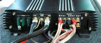
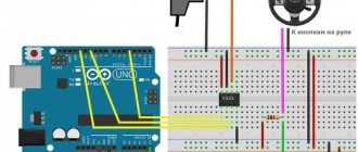
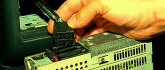
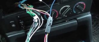
Connectors for connecting an external amplifier, active subwoofer.
In simple words, these connectors are needed to output sound. But without amplification. That is, just sound output - and you can do whatever you want with it. But most often an amplifier is connected to them, which amplifies the signal and then sends it to the speakers (speakers). There may also be an output for a subwoofer - this means that the output produces not just sound, but only a low frequency, which is then reproduced by the subwoofer. However, it is quite possible that the sub is independently capable of separating frequencies and reproducing only low frequencies, it all depends on the model of the sub. PS: note, low frequency is just bass, to make it clear.
Appearance of RCA connectors:
The audio signal in the RCA connectors implies a certain level of current. Usually this is up to 2 volts, but in premium models the current can be 4.5-5 volts, which is very good. Why? A car is a source of a lot of interference, and the higher the level of the useful signal, the less noticeable the interference that comes from the car’s electronic systems will be. What's the conclusion? Try to buy good quality radios.
If you do not come across radio tape recorders, amplifiers and other sound-reproducing equipment every day, then you may well have a question - what is this “linear output” on the radio tape recorder, why is it needed and what is the importance of their number.
The line level output is intended for connecting external audio amplifiers. These can be acoustic amplifiers, or an active subwoofer - a linear output is used to transmit sound from the source (car radio) to the amplifier.
The term “line output” refers to an unbalanced type of audio signal transmission that uses one signal conductor and ground; in automotive electronics, RCA connectors (the so-called “bells”) are used. It also assumes that the signal level corresponds to the standard. In car radios this level is usually up to 2V; some devices (high class) have a signal level up to 4.5-5V. The level of the signal at the linear output in automotive electronics is of serious importance, because the car is a source of a huge amount of interference and the higher the level of the useful signal transmitted through the intercomponent cables, the less noise induced from the electronic systems of the car will be heard.
The higher the signal level at the linear output, the better; it’s not for nothing that all high-end car radios have a high-level linear output, and this is especially emphasized in the technical specifications.
How many linear outputs should a car radio have?
Indeed, if you choose a car radio, then in the technical specifications you can read about the number of linear outputs, which can be different, for example one pair, two pairs, three pairs. The more expensive the radio, the more linear outputs it usually has “on board”. How many should there be?
- A pair. Usually found in all even the most inexpensive radios. Most often used to connect a subwoofer. It’s good when a radio with one pair of linear outputs can control the level of this output (to adjust the subwoofer); if there is a built-in filter for the subwoofer (LPF), then this is generally excellent.
- Two pairs. Usually these are front and rear outputs for building a system with “front+sub” or “front+rear” amplification. Usually these are mid-price radio tape recorders; they already have the necessary settings for the subwoofer (see above); in general, it’s great when you can turn on the low-pass filter (HPF) on the front outputs.
- Three pairs are the best option for creating a full-fledged system with an amplifier on all channels (front + rear + sub) or even complex options with channel amplification if the radio has a built-in crossover or even a processor.
The more pairs of linear outputs a car radio has, the more sophisticated an audio system can be created. When purchasing, decide how much you need.
So when buying a car radio, decide which amplifiers you will connect to it in the future. If amplifiers are not planned, then having at least one line output in stock for connecting a subwoofer is still a good idea. What if you still want to install a sub?
What to do if the radio does not have a line output?
If your car radio does not have a line output, then most likely it is either very cheap or it is a factory radio. If there is no way out but you really need it, then there are two options - one is correct and the other is simple.
The correct option is to “unsolder” the linear outputs, i.e. disassemble the radio and output the signal from it after the pre-amplifier and before the power amplifier chip. Not everyone can do this; here you need to have an understanding of the circuit design of the radio and at least be able to hold a soldering iron in your hands. You can also contact a specialist.
A simple option is to use a high-level to linear converter. This solution is quite suitable if you need to connect, for example, an active subwoofer to a standard radio, without any special complaints about the quality, because this is not an uncompromising solution in terms of sound quality.
What to do if the radio does not have enough linear outputs?
It happens that your car radio only has one pair of line outputs and you need more. For example, you already have an amplifier connected to the front speakers, but you also want to install a subwoofer with an amplifier, but there is no desire to change the radio. There are two options here:
- Removing an additional pair of linear outputs from the radio (see above) requires an understanding of what you are doing, or better yet, contact a specialist.
- Take the so-called Y-splitter. This is a simple splitter wire, there are two types and they look something like this:
Y-splitter (1 female - 2 male)
Y-splitter (1″male - 2″female)
The first option (1 mother and two fathers) is more often used when you install a four-channel amplifier. You take one interconnect wire (“line wire”, “interconnect wire”, “line”, “bells”) and connect it to the radio and pull it into the trunk. In the trunk you take this Y-splitter and thus you have two pairs of line outputs instead of one.
How to check the functionality of rulers without an amplifier?
#1 OFFLINE EWW
- From: Belarus, Brest
- Top
#2 OFFLINE bd
- From: Another one from Morelia
Good day. Pioneer DEH-4950MP radio, on the back wall there are three pairs of linear outputs. Everything is connected, all channels are activated. From ancient times there was a homemade amplifier based on TDA1562. To use the front, rear and subwoofer, I connected an amplifier to the TDA1562, and connected a subwoofer with a 10″ speaker to it. I immediately noticed that it was barely playing; I tried not to turn the volume on the radio above 50%, because... according to technical data. passport voltage/resistance of the lines on the radio: 2.2V / 1kOhm, at the same time for the TDA1562 maximum input signal voltage: 800mV (from the handheld, from the headphone output the TDA played perfectly). Later it turned out that the TDA supplies a constant voltage to the output. Question: could the linear output of the radio burn out (the most important thing)? I checked the TDA inputs are in working condition - they do not have constant voltage, which means that the linear outputs should not have burned out. The front and rear of the radio play perfectly, the rear is switched to subwoofer mode. Another question: usually the preamplifiers of the linear outputs of the radio are the preamplifiers of the power amplifiers of the radio, i.e. If the preamplifier burns out (the line output does not work), then some channel of the power amplifier will no longer work? The thing is that there is no way to check the functionality of the linear outputs; there is no voltage on them (as I understand it, the voltage appears when a load is connected. Thanks in advance for the advice. I’m worried about the newly purchased radio.
usually the preamplifiers of the linear outputs of the radio are the preamplifiers of the power amplifiers of the radio
As I understand it, the voltage appears when the load is connected.
- Top
#3 OFFLINE EWW
- From: Belarus, Brest
A counter question: was the constant at the TDA output checked relative to ground, or between the output contacts? Often there are buffers in front of the linear outputs, i.e. it's not obligatory. And there should be no load.
- Top
#4 OFFLINE FIL
- From: Moscow
I checked the constant at the TDA output between the output contacts, it gave a little less than the supply voltage. I checked the signal from the radio lines - empty, 2.2V and no smell, but checked without load, i.e. directly by the tester. It’s also interesting that I wired up a TDA amplifier at home - the TDAs ring through normally. There is an old burnt-out copy - there is zero resistance between the positive output and the power supply. There is no such thing in this amplifier, the only thing that confuses me is that between the positive input of the TDA and the power supply the resistance is about 160 Ohms, but I don’t really understand it, maybe this is how it should be. PS. Of the two more connected speakers (10-inch and S-30B) for two TDA1562, the speaker in the S-30B burned out, the 10-inch remained alive. Maybe the 2.2 Volt linear outputs of the radio eventually created such a terrible self-excitation, or what? The main question is about the integrity of the linear outputs, how can you check? It is not measured by a tester. Thank you
- Top
#5 OFFLINE Ice skating rink
- From: Kiev
- Top
#6 OFFLINE EWW
- From: Belarus, Brest
Pioneer lines most likely have feed-through conductors (and most likely polar electrolytes), so constant voltage (at low voltage, of course) is unlikely to be a problem for them. There is a risk of explosion (swelling) of the condensers, maximum, because... When a constant voltage is applied to the lines with a voltage higher than that from the linear driver, the polarity of the condenser is reversed and it turns on again.
- Top
#7 OFFLINE Ice skating rink
- From: Kiev
Today I'll check if there is voltage on the lines. But what could be the danger of connecting a 150 kOhm amplifier input to a 1kOhm output?
There is no danger.
Is there anywhere to rent or borrow an oscilloscope? three minutes, and you will see everything: whether there is a constant, and the shape of the signal, and whatever you want.
- Top
#8 OFFLINE EWW
- From: Belarus, Brest
Is there anywhere to rent or borrow an oscilloscope? three minutes, and you will see everything: whether there is a constant, and the shape of the signal, and whatever you want.
Tags: remote control
Comments 51
Just now I connected 1400ub, this wire goes to power the antenna...
download the manual for your radio and look in it for the purpose of the wires.
In your photo it says Remote, where the antenna is).
yeah, I’ve been monitoring it for half a day, all the new facts =)
Well, this is your photo)? The antenna wire has always been the remote control.
Yes? so smart) (NOT ALWAYS)
Then why post a photo of the wiring from another phone? If they tell him the colors based on this photo, but the mafon is different, he will connect it incorrectly). Conclusion, there is no need to post photos that are not related to your mafon, so that the right advice can be given and not mislead others.
The color of the wires for all GUs should, in theory, be the same, like “GOST”, at least the ones I met were all the same.
In the photo there is a white-blue wire, I have a pure blue one...
yeah, I’ve been monitoring it for half a day, all the new facts =)
nothing new, many people just can’t wait to put in their 3 kopecks) do as discussed and there will be Happiness)
Thank you for the confirmation! The second photo is from the forum, it’s not mine, but the braid looks exactly the same, so I posted it for everyone to see and didn’t worry about it at all =)
yeah thanks people, I added a photo! so far I have connected it to the Remote which is like in the picture + antennas, I will try using it =) if it doesn’t work, then I’ll hook it to the red one, according to the instructions it says that current is supplied there when the ignition is turned on! Thanks again to everyone, but write if you have anything =)
comment to the photo you connect brand 1 with brand 2 and where it is drawn + connect the antennas to the power control wire and ALL!
and if I just inserted 1 into the terminal it will work? =)
I also attached it to the antenna =))
Isn't the connector distribution written on top?
+1, blue with a white stripe, this is a plus for the radio antenna, they throw a remote on it.
thin blue or white wire on the block! You'll recognize it right away! he is special))))
You can just screw it onto the case and that’s it) There are screws on the case, I unscrewed one and secured the wiring there.
What are you talking about? Do you know where and why the REMOTE wire is connected? Why throw it at the ground?
Of course I know, otherwise why write?
You can just screw it onto the case and that’s it) There are screws on the case, I unscrewed one and secured the wiring there.
Lol myself, haven’t tried it - no stars)
You can just screw it onto the case and that’s it) There are screws on the case, I unscrewed one and secured the wiring there.
I wouldn’t bother) By the way, I have a separate one for the antenna, it only works on the radio and separately for the set)
In other places, it’s much easier to make a retractable antenna, attach it to it, I agree. I also did it wisely, I tried it on the body - everything worked as it should.
what body? did you study physics? the body is massive! that is, MINUS and PLUS is given to us!
I am aware that a plus is given! But I repeat once again, I tried to throw it like this - everything worked.
then you have a radio on which the body is a plus
It’s quite possible and I don’t deny it.
on top of everything, your body was positively charged and all the wiring inside was negative
It’s quite possible and I don’t deny it.
There are amplifiers that turn on themselves when a signal appears at the input...) so your minus is clearly superfluous)
You can just screw it onto the case and that’s it) There are screws on the case, I unscrewed one and secured the wiring there.
There are some guys who have cars that instead of - on the body have + and in the wires on the reverse instead of + -
Nonsense for me
there is still a lot of things for you NONSENSE))
It is impossible to know everything in the world, which means there is more than a lot of new things for all people.
Nonsense for me
Ahah...don’t get into it...he just mixed up the terminals on the battery :))))
there should be a white-blue wire, this is the power supply for the active antenna. Connect to it.
+1 he should be sticking out of the block by now
there should be a white-blue wire, this is the power supply for the active antenna. Connect to it.
to control the amplifier, a wire marked Amp cont, Rem is used, BUT not as a power supply for the active antenna (except for radio models where there is one Amp cont wire) if the car is a foreign car, you can use the wire from the ACC ignition switch on the radio, it is red (provided that it is connected according to the diagram and the + disappears on it when the key is turned to position 0)
In my entire life I have never seen a marking on the “AMP cont” wire. It was always written REMOTE. This wire goes to the motorized antenna (it extends when the radio is started), but if there is no motor antenna, everyone always attaches a cable to this wire so that it, like the antenna, starts up with turning on mafun. As for ACC, this provision is not available in domestic cars, but as always there is an alternative: a plus is supplied on the first contact of the ignition switch block when the key is inserted
if the wire is intended to control the antenna, then on it + disappears when changing the radio mode, for example, when turning on the disk (you haven’t seen much yet))
never disappeared, I installed more than 50 different radios, in my opinion that’s enough
There is something like this on Alpine radios: one blue wire, the other is blue and white, one is on the antenna and the other is on!
Amplifier purpose
At the initial stage, it is necessary to decide what the car enthusiast wants to get in the end. Typically, when installing a car amplifier in a car, two goals are pursued:
- improving the quality of the audio signal output from the car speakers;
- increasing the overall volume of music tracks.
Car amplifier
A car amplifier is a universal device that allows you to increase the output signal level. In everyday life, many people use home theaters that include an amplifier. But household appliances typically use a 220-volt power source, while automotive systems are powered by a 12-volt on-board network. That's why such amplifiers are called automobile amplifiers.
Origin of the concept
In the first decades of the existence of terrestrial radio broadcasting, the only way to transmit programs between stations included in the network was landline (wired) telephone communication. The range of the radio broadcasting stations themselves was short, and the quality of receiving programs over the radio channel was unsatisfactorily low for relay purposes; Satellite radio communications did not exist in principle. Almost immediately after the first experiments in telephone broadcasting, radio broadcasters and telephone operators needed to agree on technical requirements for the transmitted signal. A signal that was too strong overloaded the telephone equipment; a signal that was too weak was overly susceptible to noise and interference. In 1940, US radio broadcasters and the telephone monopoly AT&T recorded technical requirements in a standard in which they gave a firm definition: “line level is the average level of a sound program at which 1 mW of electrical power is released in a subscriber load with an input impedance of 600 Ohms.” The logarithmic measurement scale tied to this level is designated dBm (decibel relative to the level of 1 mW). It was with this scale that standard “sound” (VU-meters) were graduated: zero conventional units VU (which actually lies in the right half of the voltmeter scale) corresponded to a voltage of 775 mV.
Over time, the permissible signal level on the line has increased; in 1954, the standard line level of US telephone networks increased to +8 dBm (6.3 mW into a load of 600 ohms, or 1.95 V); the permissible maximum signal level then was +18 dBm, which guaranteed an overload margin of 10 dB relative to the line level. At the same time, it became obvious that the germanium rectifiers built into standard VU meters introduce unacceptably high nonlinear distortions into the signal on the line (0.3% at the maximum level and much more at lower levels). To avoid these distortions, engineers began to connect a ballast resistor in series with the VU voltmeter, which increased the input resistance of the device and at the same time reduced the voltage at the voltmeter input by about one and a half times, or by 4 dB. A new industry standard soon emerged within broadcast networks: the VU voltmeter zero was now +4 dBm, or 1.228 V into 600 ohms. It was this level that was used as a linear level in studio equipment of broadcast networks.
In the 1970s, the situation changed: a mass market for household equipment for high-quality sound reproduction developed, and a new market for semi-professional studio equipment emerged. The studio standard of a 600-ohm line, which implied the use of broadband matching transformers, was too expensive for budget equipment, and was not necessary. It was enough that the output impedance of the signal source was many times lower than the input impedance of the receiver. Thus, the need arose to move from “power” decibels dBm to a new scale that operates not with power, but with voltage. The Americans, following tradition, simply equated the voltage scale zero to the dBm scale zero; the new logarithmic units were designated dBu (from the English unterminated, “unloaded”). In Europe, they proposed a new scale, tied not to the level of 775 mV, but to the level of 1 V - this scale was designated dBv. The dBV scale, standardized by the IEC and IHF, has become the main one for household appliances; The dBu scale, like its predecessor dBm, has remained the standard for professionals.
Line output on the standard Toyota radio
Unsoldering linear outputs from a standard radio is not a complicated process, but it requires care and a responsible approach. Especially if you do it yourself. The first thing you need to start with is selecting a microcircuit. Its appearance is shown in the photo. Moreover, it is connected to the radiator.
Once the circuit has been determined, markings must be installed. Next, you can start searching for the datasheet. This will allow us to determine which wiring is already on the circuit, and which one can be used in our case. This information is extremely important, since a signal is received from the input.
Recently, set-top boxes that reduce the signal level have become especially popular. This design is quite simple and has no special features. Therefore, everyone can handle its preparation and setup. It is enough to use the appropriate scheme.
Soldering a linear output from the radio using a preamplifier is very similar to the previous one. The course of action is no different. Therefore it works the same way.
Useful information about cassette player wiring
What is the difficulty of desoldering a radio?
Let’s say right away that you can solder the head unit yourself only if you understand circuit design, know how to distinguish a capacitor from a resistor, and already have experience working with electronic devices. And yet, the ability to tin and solder does not guarantee the success of the event. This is due to the following features of modern radios:
- Complex circuit and dense placement of parts on the board.
- Sensitivity to overheating; the microcircuit can be damaged even with short-term thermal exposure.
- Depending on the features of the radio circuit, it may be necessary to significantly change the device circuit with the selection and soldering of additional parts with certain parameters.
In 50 cases out of 100, independent intervention in the structure leads to failure of the radio. In this case, the repair will cost more than the cost of services for desoldering the radio at the service center. Therefore, you still shouldn’t experiment on your own.
Well, for those who have decided to take this independent step, below we provide standard information about wiring. After studying this information, you will get an idea of where you will have to solder additional inputs and outputs. Without knowing these basics, there is no point in opening the radio at all.
Wiring of linear outputs
Most stock radios only have the minimum outputs required to connect the manufacturer-installed speakers. The rejection of additional connectors is primarily justified by the need to prevent the connection of additional devices. The only solution that is offered is the opportunity to purchase a more advanced head unit, but in a completely different price range. In this way, trim levels with a minimum of changes are often pushed through at an inflated price.
Therefore, a more reasonable, that is, cheaper, solution to the problem would be to wire the linear outputs from an existing radio. The procedure is standard, service technicians often solve similar problems, so it won’t take much time, just a couple of hours. And the possibilities for building an improved acoustic system are significantly expanding.
Why is it required
What path do most amateurs who encounter such a problem take? They simply connect the amplifier to the installed speakers. But they receive a signal already amplified by the radio. Therefore, the need arises to install a converter that will allow you to obtain an audio signal with the parameters necessary for the amplifier. Without such a block, it is only possible to connect equipment equipped with a high-level input.
It would seem that everything is simple. But such a solution has several significant disadvantages:
- The amplifier built into the standard equipment is characterized by the signal distortion coefficient. And for most models this figure reaches 10% or more. That is, the sound passing through the radio amplifier is already far from ideal.
- During reverse conversion, which occurs when a signal is taken from a high-level output, the quality deteriorates by an order of magnitude. Therefore, it is simply impossible to get clear sound even with high-end amplifiers and speakers.
Based on this, it becomes obvious that it is necessary to capture a linear audio signal before it is amplified. This is what we do by wiring the radio outputs.
Where to unsolder the linear outputs
The block diagram of almost any radio contains such blocks as a preamplifier and a power amplifier. And it is between these devices that you will need to solder the outputs you need to connect the amplifier. The general scheme of work is as follows:
First of all, you need to find a standard power amplifier. Typically this chip is located on a radiator mounted on the rear wall of the radio. Therefore, it is quite possible to find it even without a circuit diagram. Determine the brand of the amplifier and use it to find the pinout of this element on the Internet. We will need a low side input, the signal to which is supplied from the preamplifier. Having determined the required legs of the microcircuit, we select a convenient place for desoldering
Please note that for individual circuits you will have to use additional parts, usually capacitors, the capacitance of which depends on the characteristics of the circuit. You need to select the denomination based on the characteristics of the device. Standard connectors (bells) are soldered onto the resulting outputs, which are not difficult to find and buy.
Connecting with tulips
To correctly connect the wires to the RCA connectors, you need to remove the radio from the panel in the car and find the linear output block on the back wall. It is usually labeled Line Out. The tulip sockets are marked SUB, Front and Rear and are intended for connecting an amplifier, subwoofer and various speaker systems. The likelihood of finding at least two pairs of bell outputs on standard radios is not great. And many have to part with standard models and replace them with newer and more advanced ones.
But what to do if a car enthusiast does not have the funds to buy a more advanced model with the required number of outputs, or the radio is too expensive for the owner, and he does not want to part with it? What to do if there are not enough RCA outputs? Let’s say you’ve already connected to an amplifier for one pair of speakers, and the desire to also connect a subwoofer intensifies every day.
In this case, there are two solutions to this problem:
- Use additional equipment to output another pair of linear outputs.
- Use a so-called “Y” splitter or adapter.
Using the latter, you can compensate for the lack of linear outputs on the car radio.
From what has been written above, it becomes clear that connecting tulips to a radio to solve acoustic problems in the interior of your favorite car is not a very difficult task. The main thing is to understand the significance of this or that connection. Evaluate the importance and purpose of connected equipment. And it doesn’t even matter what kind of radio is installed in your car, an old Pioneer or a modern system with a quad-core processor. In the modern world, you can solve any problem of connecting speaker systems in a car.
If you do not come across radio tape recorders, amplifiers and other sound-reproducing equipment every day, then you may well have a question - what is this “linear output” on the radio tape recorder, why is it needed and what is the importance of their number.
Car speakers and subwoofers
There are two types of car speakers:
- Coaxial;
- Component.
Coaxial speakers include several components at once - these are low, mid and high frequencies, which are grouped in one housing. Component speakers, unlike coaxial speakers, on the contrary, are divided into different elements - these are low and mid frequencies, high-frequency drivers and a filter (crossover) that regulates and directs the sound to the desired frequencies.
To check car speakers, just connect the car radio to a power supply, insert a disc or other media with existing music tracks. After connecting the car radio, you need to connect speakers to it. The wires with audio output in the radio are marked with color (see above). There are 4 pairs of such wires; you need to select one pair of wires and connect them to the terminals installed on the speaker itself. The wire with a black stripe plays the role of a minus (ground), it must be connected to the terminal with a minus sign.
If the polarity is not indicated on the speaker terminal, it’s okay, connect at your discretion, the speakers can reproduce sound in reverse mode.
Audio interface software.
When it comes to system stability and usability of your audio interface, software is of great importance in addition to extensive and high-quality hardware.
3.1 Device drivers
For your PC, a device driver is like a manual for your audio interface. This ensures that all analog hardware channels are correctly recognized and available in your DAW. It also gives your system access to any items that can work with the software, such as phantom power or PAD. The usability of your audio interface makes or breaks a stable, fault-tolerant device driver. Unstable device drivers are real quality killers with every entry, but fortunately they are quite rare these days. It is best to find out in advance what device drivers are available for the desired audio interface.
3.2 Audio buffer, sample size and latency
Audio buffer size, also often called sample size, is an important software feature. It specifies how much audio data your interface can store in a buffer before the data is sent to your processor for processing
The smaller the buffer size, the lower the latency, but the higher your CPU usage. If, for example, you can't use zero-latency monitoring for some reason and you need to loop the signal for recording through your computer, you're at the mercy of small buffer sizes. The buffer size is usually specified in milliseconds (ms) or samples, depending on the audio interface and manufacturer.
3.3 Internal mixer
The internal mixer is the heart of the software and the control center of the audio interface. Here you can, for example, change the routing of input and output channels or set up monitoring for different musicians. The mixer is often of minor importance with small interfaces, but becomes increasingly important as the number of channels increases. If you want to record many channels simultaneously and provide monitoring for multiple musicians, setting up a mixer can quickly become a daunting task.
Conclusion
Whether two or 32 channels, modern audio interfaces offer a wide range of features. Of course, there is a learning curve to understand all the features of your audio interface and how to use them effectively, but you shouldn't let that hold you back. Finding the right audio interface is not as difficult as it may seem if you know in advance what application you want to use it for. However, with this short overview of the features you shouldn't have any more serious problems, and if you want to know more about it, your best bet is to read Thomann's guide to audio interfaces.
HiFiMAN players:
How to connect a subwoofer to a standard Sony radio.
connecting the subwoofer to the standard radio. nuances of installation in cars of different brands A wide range of models from the American manufacturer HiFiMAN allows you to choose a player to your taste even if you are guided solely by its appearance. The original solution of the manufacturer is the presence of a switch from a regular to a balanced 3.5 mm TRS port.
HiFiMAN HM-901s: TRS jack, balanced output (3.5 mm jack);
HiFiMAN HM-901: TRS jack/balanced output (4-pin port, supplied with an adapter; switch provided);
HiFiMAN HM-802: TRS jack/balanced output (4-pin port, supplied with an adapter; switch provided);
HiFiMAN HM-700: TRS jack/balanced output (4-pin port, supplied with an adapter; switch provided);
HiFiMAN HM-650: TRS jack, balanced output (3.5 mm jack);
HiFiMAN HM-603: TRS jack, balanced output (3.5 mm jack);
HiFiMAN HM-601 Slim: TRS jack, balanced output (3.5 mm jack).
We can talk endlessly about ports, plugs and the type of signal transmission. The only true advisor can be your own ears. Any of the models presented in this material sounds an order of magnitude better than a smartphone and a budget flash drive with MP3 support. This is Hi-End.
(5.00 out of 5, rated: 2)
