A voltmeter in a car is a rather rare feature. This probably happens because the average motorist is unlikely to often think about voltage, which cannot be said about those who like to keep everything under control... Installing a voltmeter in the car yourself will help you always be aware of the “volts”!
Which voltmeter to choose?
It is extremely difficult to find a car voltmeter, and even a decent looking one, in stores. This happens because such equipment is installed from the factory in literally single cars. If we discard the tuned instruments, then in reality you can only find voltmeters from the VAZ-2107 and UAZ.
The voltmeter from the VAZ “Seven” does not have a housing and this is a huge minus. According to the “statement”, it is attached to the dashboard and “naked” consists of unprotected windings on a small frame and an arrow made of soft metal...
The UAZ voltmeter is a full-fledged device in a sturdy case. The only real negative is the appearance. It is, as befits this car, extremely unpretentious, even military.
The design and quality of the voltmeters considered are unlikely to be suitable for beautiful tuning. Therefore, for those who not only add functionality to their car, but also take into account the interior design of the car, it is better to look for a specialized tuned device.
Connecting a voltmeter to a car
Ideally, the voltmeter should be connected to the positive terminal of the battery - then it will show the most accurate charging voltage. It is required to conduct a wire from the terminal into the interior to the place where the device will be installed. Before starting work, you need to disconnect the battery, take a wire with a cross-section of about 0.5 mm and stretch it into the cabin along the standard wiring harness. It is quite possible that for this you will have to disassemble some of the casing and run wires under the dashboard.
The voltmeter should only work when the ignition is on. When connected directly to the battery terminal, it will be constantly on. You can get around this problem using a conventional electromechanical relay, which is used in abundance in any car.
You can read in detail about how a relay works in a car and how to connect through a relay by following the links. Installing a voltmeter in a car follows the same scheme, namely:
– The wire going from the battery to the device is “power” in this case. A relay is installed in its gap, which, when turned off, opens this wire, turning off the voltmeter.
– We take the voltage to the “positive” control contact of the relay from the place where it appears when the ignition is turned on. It could be anything - a mounting block, ignition switch wires, and so on.
– We connect the “minus” of the voltmeter and the second control contact of the relay to “ground”, that is, we screw it to the body with a standard “bolt” terminal.
Now, when you turn on the ignition, the installed relay will operate, connect the voltmeter, and it, in turn, will show the number of volts in the on-board network.
Voltmeter protection and backlight
At this point, installing a voltmeter in a car may be completed, but ideally two more steps need to be performed - one for safety, and the second for comfort.
To protect the voltmeter's power circuit from a short circuit, it is necessary to install a fuse on the wire coming from the battery. This is very simple to do, just cut this wire in a suitable place, crimp two female terminals on it and put them on the terminals of the fuse. Its rating should be small, for example, 5A (More details about fuse ratings are here). It is better to wrap the terminals, and for reliability, the fuse itself, with electrical tape.
And finally, the final step is to illuminate the voltmeter. All devices that are placed in the housing must have it. It is necessary to extend the wire to the backlight contact from where the voltage appears when the side lights are turned on. The “minus” of the backlight, as a rule, is combined with the common negative terminal of the device, and in our case it is already connected to the car body.
Connecting a voltammeter DSN-VC288 100 volts 10 amperes. It's simple
Good morning, afternoon and evening Dear DIY masters!
Today I want to tell you about one of the most popular Chinese measuring instruments today, the DSN-VC288 volt-ampermeter. With operating parameters for measuring voltage from 0 to 100V and current from 0 to 10A.
The DSN-VC288 volt-amperemeter, today, is one of the most popular and in demand for measuring voltage and current among radio amateurs and DIYers. Installed on various electrical devices. The price of this device is very budget-friendly. In online stores it ranges from 100 to 200 Russian rubles. Which today can be considered practically a gift.
The DSN-VC288 volt-ampermeter is not very suitable for assembling a laboratory power supply. Since the minimum step for indicating current readings is 10 ma. Incl. It can be placed in a LBP with not too high requirements for the accuracy of measuring the output voltage and current. That is, in a home power supply where very high accuracy is not required.
This device is very easy to connect. This device has two connectors. The 3-pin connector serves to supply power to the device itself. After all, this is an electronic system and also likes to consume electricity, although quite a bit. The power supply of the volt-ammeter fits into a plug from 5 to 30 V. Contact for removing the measured voltage on the load. The measured voltage is the voltage that we will take directly from the load from 0 to 100 V. The third contact is a minus. The 2-pin connector is used to measure the current in the circuit. It is connected to the circuit through the negative in series from the power source to the load. Also on the board of the DSN-VC288 volt-ampermeter there are two trimming resistors. Which serve to calibrate the indication of the measured voltage and current, respectively.
Many who have encountered the above-mentioned measuring device are dissatisfied with the low quality of the calibration trimmers. Here, as they say, some are lucky and some are not so lucky.
As always, a little about safety precautions. This is important, respect electricity, do not stick your fingers into the socket, do not measure the voltage with your tongue and it will not touch you.
For those who like to watch rather than read, I suggest watching, with pleasure, a video clip with a detailed description of connecting the DSN-VC288 voltammeter.
Is it necessary to install an ammeter on a VAZ?
To the question “is it worth installing an ammeter on a VAZ?” The Internet is literally teeming with discussions. But everyone decides for themselves whether to do it or not, especially since it can be done beautifully and elegantly - make some kind of case, attach a stand, and so on. But when installing an ammeter, one should not forget an important thing, such as the fact that all this work will be connected with electricity, and more specifically, with a large cross-section wire, which in turn is connected to the battery without any fuse. If
If you are an expert in this area or such difficulties simply do not frighten you, then I think you can move on to the actual installation of the ammeter.
I made this decision because my watch simply did not work, and I thought that the ammeter would look quite nice in this place. In this article I would like to talk only about the theoretical part of installing an ammeter, and describe the practical part in more detail in the next article.
Video instruction:
Tools for connecting the measuring device:
1. A soldering iron, preferably designed for soldering electronic circuits, and not old basins. 4. A benchmark tester you trust. To check the accuracy of measurements using our device, voltage and current. And further calibration of the DSN-VC288 voltammeter. 5. Any load for control measurement (you can use an LED lamp of the appropriate voltage). 7. A utility knife for stripping insulation and preparing wires for soldering.
Consumables for connection:
1. Solder. 2. Soldering acid or rosin. 3. Set of wires for installation. 4. Insulating materials, electrical tape or heat shrinkage. 5. A little electricity to test the device.
Measuring circuit voltage using a voltmeter
The voltmeter device helps measure the potential difference in an electrical circuit. To minimize the impact on the network, the device should have the highest possible resistance. It determines the measurement error and sensitivity of the device. In the process of improvement, voltmeters have gone from point-type, analog instruments to discrete ones with digital indicators. Voltage measurement has become an integral function of most multimeters and electronic oscilloscopes. Voltage measurement and indication are used in some extension cords, residual current devices and circuit breakers.
Clock connection diagram
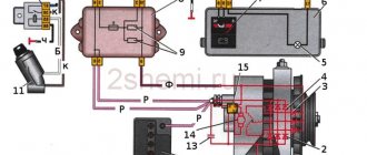
With the release of the “Six”, the VAZ 2106 watch did not undergo any fundamental changes. The clock connection diagram, which can be viewed here, has not changed either. The circuit diagram of the clock is tied to the ignition switch and the safety element block. At the same time, the kinematic diagram for connecting the VAZ 2106 watch is designed in such a way that the chronometer works regardless of the position of the ignition key, i.e. The "six" clock works even when the ignition is off.
If the problem is connecting the VAZ106 watch, then there is nothing complicated in this technical operation, and no difficulties are foreseen. At the same time, when solving the problem of how to connect a clock, you need to connect one wire to ground, and connect the remaining two plugs to +12 volts to the clock network and to its backlight. According to the color of the wires, which can be different, the positive wires should be the same color, usually red, and a black braided wire should be attached to ground.
When buying a VAZ 2106 watch, the price of these products is small, but due to the fact that they are morally outdated due to their low information content, car enthusiasts initially install the same chronometers from the “seven” instead of watches, and many tune this device with LED backlighting or insert such a timing device from foreign vehicle models.
Taking into account the simplicity of the design, this element of the car’s instrumentation rarely fails, so such an operation as repairing a VAZ 2106 watch needs to be resorted to quite rarely. However, in practice there are cases when watch repair is simply necessary due to its failure.
Connecting the device
Voltage control always occurs in parallel. The measurement can be carried out at both the power source and the load. The voltmeter connection diagram is shown in the figure below.
Subtleties that must be taken into account before connecting the voltmeter:
- A correctly selected measurement range will protect the device and the circuit under test from damage. Particular care should be taken when the voltmeter reading is close to the limit. A jump in EMF can burn the windings of the measuring device;
- A pointer voltmeter can provide standard accuracy only if positioned correctly. If the device indicates horizontal placement, then placing it vertically is prohibited, and vice versa. You should also pay attention to the absence of vibrations and strong magnetic fields;
- Measurements with a voltmeter can be performed both under voltage and by disconnecting the circuit from the power source and then turning it on;
- When working with dangerous voltage levels, it is recommended to use protective gloves and dielectric mats;
- When using an analog device, before starting measurements, you must check that the arrow points exactly to zero. If necessary, adjust using a special adjusting screw;
- If necessary, calibration is carried out;
- To ensure high accuracy of measurements, you should check how long ago the voltmeter was verified.
Often devices have several measurement limits. Analog voltmeters use different connection diagrams for each value. In digital ones, it is enough to place the pointer opposite the required value. The most modern devices are able to automatically determine the measurement limit and change it during voltage monitoring.
Installation specifics
If there are no problems during installation with digital voltmeters that are powered from the cigarette lighter, then models installed directly into the dashboard often force drivers to think about the order in which they are connected.
Most voltmeters on the market have two or three wires for connecting to the network, although there are models with four contacts. The wires have standard color markings:
- the red wire corresponds to “plus”;
- the black wire is connected to the negative;
- The white wire is responsible for controlling the backlight intensity and turning the device on and off.
In some cases, an unexpected problem arises when connecting the voltmeter in this way: it lights up dimly or refuses to work at all. The reason may be the alternative marking of the wires, in which the white wire is responsible for the “minus”, and the black wire for controlling the device.
The voltage sensor is installed in the standard place of the clock, but in some cases, when it is impossible to find free space for the voltmeter, you have to make a hole for it directly in the dashboard.
An excellent place to connect the device is the dashboard plug on the left side of the steering wheel. It is small in size and easy to remove and secure for processing.
Figure 1. Connection diagram for a voltmeter with a pulse stabilizer.
The voltmeter body has a raised surface: the frame around the display will protrude above the surface of the car panel. Thanks to this, the device will not fall inside the mounting socket, and will also hide uneven edges of the hole.
Inexpensive models of voltmeters may not have a separate wire for power; such a device is connected via three contacts on the sensor body (Fig. 1). In this case, the voltmeter is connected using a 4-wire wire from the computer drive (Fig. 2). The wide IDE format connector is cut off, and the remaining wiring is attached by soldering to the contacts of the car wiring. The 4-pin contact ensures a good connection and makes it possible, if necessary, to quickly and effortlessly replace the voltmeter if it breaks down.
Regardless of the structural features of the voltmeter, before installing it, the car’s wiring diagram is studied in detail, according to which the location of the device’s connection is determined. It would also be a good idea to carefully read the instructions for the device, since the methods for connecting it may differ.
Classification of voltmeters
DC voltmeters are used to measure voltage in networks with constant voltage. It is usually based on a magnetoelectric system. During operation they are highly susceptible to external influences, therefore they are used with shielding.
An AC voltmeter is used to measure sinusoidal voltage with a frequency close to 50 Hertz. The electromagnetic system is most often found in analog devices. It has a non-linear scale, which makes it difficult to take readings.
Selective voltmeters are designed to measure the root mean square value of an individual harmonic voltage component. It is based on an electronic voltmeter designed to operate with direct current. The operating principle of the device is similar to a superheterodyne radio receiver.
How to install a voltmeter on a VAZ 2106 with your own hands
Perhaps, if not all, then many, the owners of the “six” (BA2106), in addition to the set of instruments provided by the designers, would not refuse to equip their car with a voltmeter. Installing it is not difficult, and for this you will need the device itself, a few screwdrivers, wires and a little of your time.
To do this, however, you will have to sacrifice hours, because... a voltmeter is most often installed in their place in the middle of the torpedo. This loss is not significant, because the watch is not particularly original, and many drivers have wristwatches, but a voltmeter will come in handy more than once in operation. After all, thanks to this device, you will be able to see even minor problems and fluctuations in the functioning of the generator and promptly respond to troubleshooting.
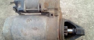
By the way, the voltmeter from a UAZ car is exactly the same size as a watch and can be installed in the dashboard without any problems. Also prepare a female terminal and a wire about 25 cm long. Be extremely careful when working with electrical wiring.
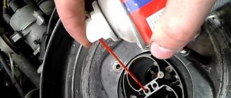
First you need to remove the terminal from the battery. Then remove the clock from the car dashboard. Pull the watch out of the dashboard along with the watch socket and the backlight lamp, while removing the sealing ring from them. The voltmeter is connected via a positive wire, which is connected in the glove compartment to its backlight bulb.
Analog and digital devices
Analog devices are based on electromagnetic, magnetoelectric, and electrodynamic systems. Similar types of designs are incorporated into ammeters. To increase the measurement limits, shunts are used. After the measurement, it is necessary to take into account the resistance of the additional resistor in the resulting result.
One of the main disadvantages of analog devices is high power consumption. Connecting such a voltmeter can lead to a voltage drop in the circuit, which will affect the error. The presence of inductance in the design causes sensitivity to the frequency of the measured voltage.
The design of a digital voltmeter is based on an ADC. The measurement accuracy is determined by the sampling with which the analog-to-digital converter operates. The voltmeter indicator displays the finished result in digital form, which greatly facilitates working with the device. The impact on the network for such devices is minimal due to the presence of their own power source.
The widespread use of discrete voltmeters has led to their integration into other devices. Most multimeters have the ability to measure DC and AC voltage. At the same time, to increase the accuracy of measurements, several limits are provided in the design. The high resistance of the voltmeter allows you to reduce its influence on the circuit to which the measuring device is connected.
Selecting a voltmeter model
Digital voltmeter circuit.
The modern market of devices for cars offers a wide selection of voltmeter models. The most popular types of devices are:
- analog “pointer” voltmeters - installed mainly on domestic cars, connecting to the dashboard instead of a clock;
- digital sensors connected to the cigarette lighter socket;
- digital voltmeters mounted in the dashboard.
The last two types of devices are most often used, as they combine a modern appearance, accurate readings and ease of installation.
The measurement results that best correspond to reality are provided by voltmeters connected directly to the dashboard. Although their installation is sometimes fraught with some difficulties, by installing them you can get constant monitoring of the battery condition, which is especially important when there are a large number of connected nodes.
The cost of a digital voltmeter is quite low and ranges from 120-150 rubles if ordered through online stores. It has a standard rectangular shape, thanks to which it will harmoniously fit into the interior of any car. Backlight color - white, yellow, blue, green, red. Sometimes a problem arises with the high brightness of the screen, which acts as a distraction and makes it difficult to concentrate on the road, but this problem can be quickly solved with the help of a tint film.
Main technical parameters
The main technical characteristics of the voltmeter, included in the user manual and the device passport, in accordance with international standards:
- internal resistance of the voltmeter;
- measurement range within which the specified accuracy is ensured when the device is correctly connected;
- when working with alternating voltage, the operating frequency is indicated.
One of the most important parameters is the accuracy class. It is always displayed on the instrument scale. With its help, you can determine the error with which the result is obtained after connecting the device to the network.
Hours of freedom
The instrument panel of the “six” is quite informative; it contains instruments for measuring speed, engine speed, an oil pressure sensor, a coolant temperature sensor and a sensor showing the remaining amount of fuel in the fuel tank.
As for the operation of the generator device, if there is no energy regeneration, the “control” lights up. But this already becomes known after the generator fails. To prevent the creation of such a situation, it is advisable to install a device such as a VAZ 2106 voltmeter clock, which is already equipped with VAZ-2105 cars of the last 07 years of production.
For this installation you will need:
- UAZ voltmeter,
- Electrical wire 20-25 cm,
- Special input connector (“female”)
Important note: when repairing electrical devices and connecting circuits, it is necessary to de-energize the equipment by removing the negative battery cable from the connector. This is necessary to prevent short circuits and failure of the vehicle’s electronic equipment.
Algorithms for setting the clock of the VAZ 2106 voltmeter
- We remove the factory clock on the VAZ 2106 from the mounting location, disconnect the supply wiring;
- We connect the clock of the VAZ 2106 voltmeter to the positive contact of the backlight of the interior box. The contact is activated when the ignition is turned on.
- It is not possible to use the factory electrical circuit on the chronometer due to the constant activation of the contact, which can lead to battery discharge if the vehicle is stored for a long time;
- We lay the leash from the place where the chronometer is fastened to the side of the interior box to the place where the device is illuminated and connect the wires in the required way, and fasten the output end of the wire with a “female” connector;
- Remove the voltmeter fasteners;
- To securely fasten the voltmeter, we wrap it in several layers of fabric insulating tape. We install the ring - the seal from the chronometer, the backlit cartridge and connect the wiring;
- We insulate the old wire from the red “six”, because it is under constant voltage.
After this, we install the new device in the mounting location.
Description of some types of measuring devices
The V3-57 microvoltmeter is capable of operating with alternating voltage from 5 Hertz to 5 MHz. The result is displayed by calculating the root mean square value. The device is capable of working with voltages of any shape. The resistance of the voltmeter is at least 5 MOhm. The device is most widely used in radio engineering for setting up equipment.
AKIP-2401 AC voltage meters have two channels. It is also possible to fix the result on the screen using the “Hold” button. The device has an RS-232 interface that allows you to read data remotely.
The V7-40/1 device is primarily used for high-precision scientific research and verification of other voltmeters. Its resistance reaches 2 GOi with a measurement limit of 2 V. This makes it possible to minimize the influence on the circuit, which is important when working with low-voltage radio circuits. B7-40/1 is successfully used in automation equipment and SCADA systems.
Installation specifics
Table of characteristics of a digital voltmeter.
If there are no problems during installation with digital voltmeters that are powered from the cigarette lighter, then models installed directly into the dashboard often force drivers to think about the order in which they are connected.
Most voltmeters on the market have two or three wires for connecting to the network, although there are models with four contacts. The wires have standard color markings:
- the red wire corresponds to “plus”;
- the black wire is connected to the negative;
- The white wire is responsible for controlling the backlight intensity and turning the device on and off.
In some cases, an unexpected problem arises when connecting the voltmeter in this way: it lights up dimly or refuses to work at all. The reason may be the alternative marking of the wires, in which the white wire is responsible for the “minus”, and the black wire for controlling the device.
The voltage sensor is installed in the standard place of the clock, but in some cases, when it is impossible to find free space for the voltmeter, you have to make a hole for it directly in the dashboard.
An excellent place to connect the device is the dashboard plug on the left side of the steering wheel. It is small in size and easy to remove and secure for processing.
Figure 1. Connection diagram for a voltmeter with a pulse stabilizer.
The voltmeter body has a raised surface: the frame around the display will protrude above the surface of the car panel. Thanks to this, the device will not fall inside the mounting socket, and will also hide uneven edges of the hole.
Inexpensive models of voltmeters may not have a separate wire for power; such a device is connected via three contacts on the sensor body (Fig. 1). In this case, the voltmeter is connected using a 4-wire wire from the computer drive (Fig. 2). The wide IDE format connector is cut off, and the remaining wiring is attached by soldering to the contacts of the car wiring. The 4-pin contact ensures a good connection and makes it possible, if necessary, to quickly and effortlessly replace the voltmeter if it breaks down.
Regardless of the structural features of the voltmeter, before installing it, the car’s wiring diagram is studied in detail, according to which the location of the device’s connection is determined. It would also be a good idea to carefully read the instructions for the device, since the methods for connecting it may differ.
Security measures
Unlike other devices, such as an ohmmeter or a megometer, when working with a voltmeter, you have to deal with voltage. At small values it does not pose a danger to humans. Great care must be taken when measuring voltages that can create a dangerous current flowing through the human body.
Voltage measurements must be accompanied by full compliance with safety regulations and operating regulations. This will prevent electrical injury. It is prohibited to work without protective equipment, such as rubber gloves and mats. Upon completion of the work, there should be no exposed live parts that could cause accidental contact by maintenance personnel.
The widespread use of voltage measurement in electrical engineering has led to the creation of voltmeters of various designs. They differ both in operating principle and in accuracy. The most popular are universal devices that can automatically select not only the limit, but also the type of controlled value.
“Six” watch repair
The chronometer malfunction may be of the following nature:
- a mechanical defect in the mechanism of the “six” watch; in this case, do not carry out repairs, but immediately begin replacing the product;
- malfunction of the device lighting system;
- failure of electrical parts or their connections.
In the event of malfunctions in the electrical part of the product that can be eliminated during repair work, it is necessary to dismantle the device and replace the faulty elements.
Removal and installation of the chronometer
- We prepare the vehicle and tools for repair work;
- Disconnect the negative wire from the battery (disconnect the vehicle ground);
- Using a screwdriver, pry the plastic ring through the grooves on the side of the watch and pull the product out of the installation location;
- The retaining ring is removed with the product;
- When replacing the clock backlight of a VAZ 2106 car, a W3W electric lamp is used, which must be unscrewed from the installation socket and replaced;
- When removing the device, mark the wires and disconnect them from the contacts of the product;
- During installation (reinstallation), we fasten the installation ring, aligning the protrusions with the holes on the instrument panel;
- We connect the marked wires and secure them to the instrument panel.