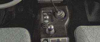
1. Place the car on a lift or inspection ditch and hang the front of the car. 2. Remove the anti-roll bar, suspension cross member braces and engine crankcase skid plate. 3. Disconnect the shock absorbers from the lower suspension arms, and the front driveshaft from the drive gear flange of the front axle reducer. 4. Compressing the suspension spring, disconnect the ball joint from the lower arm and remove the spring, smoothly unloading it. Disconnect the steering linkages from the steering arms. 5. Remove the cap and unscrew the wheel hub bearing nut. 6. Perform the same operations on the other end of the suspension. 7. Loosen the clamp connecting the exhaust pipe to the muffler pipe, disconnect the suspension of the pipes and mufflers at the rear of the car and on the gearbox. 8. Using wrench 02.7812.9500, unscrew the nuts securing the front muffler pipe to the exhaust manifold and remove the pipe downwards. 9. Unscrew the nuts securing the engine front mount cushions to the suspension cross member brackets. 10. Supporting the front axle, unscrew the bolt securing the right bracket 22 to the engine and the two nuts securing the front axle on the left side (see Fig. Front Axle). 11. Raising the engine 25–30 mm, remove the front axle assembly with the front wheel drives.
1. Installation of the front axle on the vehicle is carried out in the reverse order of removal. 2. When installing the bridge, tighten the fastening nuts and bolts to the torques specified in subsection 1.8. 3. Fill the front axle housing with transmission oil through the oil filler hole; the oil level should reach the lower edge of the hole.
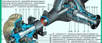
VAZ-21213 (Niva). Dismantling the front axle
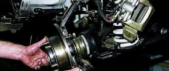
1. Install and secure the front axle on the repair stand. 2. Remove the plug and drain the oil from the crankcase. 3. Unscrew the nuts securing the bearing cover of the inner hinge housing and remove the hinge, being careful not to damage the sealing gasket. 4. After removing the retaining ring and spring washer, press the bearing off the inner joint housing and remove the seal. 5. Remove the stamped axle housing cover and gasket. It is not recommended to remove the bottom cover. 6. Disassemble the front axle gearbox using the techniques described in subsection 3.5.3.
Possible faults
The need to adjust the elements of the front axle is assessed by the presence of noise and vibrations that occur in various operating modes of the VAZ 21214. Thus, conditionally acoustic signs can be divided into two groups: • Constantly recorded; • Fixed during braking with the help of an internal combustion engine or acceleration.
The nature of the sounds may resemble: • Howling (wear of the main pair); • Crunching, “trolleybus” hum (destruction or overtightening of the shank bearings, unscrewed drive shaft nut, axle bearings, incorrect adjustment of the gearbox gears); • Intermittent “shuffling” (differential bearing). The difficulty of diagnosis lies in the abundance of extraneous noise produced by other components of the car.
Differences in VAZ rear axle gearboxes
RZMs differ in the gear ratio of the main pair; in total, there are four types of gearboxes on the VAZ classic:
- 2101;
- 2102;
- 2103;
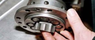
The slowest one is the RZM 2102, its drive gear has 9 teeth, and the driven gear has 40 teeth. To calculate the gear ratio, you need to divide the number of planetary gear teeth by the number of teeth on the drive shaft; for the VAZ 2102 the drive gear is equal to 4.44.
The “penny” gearbox (2101) accordingly has the number of teeth on the gears 10/43, so its IF is 4.3. The next, faster one is RZM 2103 - it has a ratio of 10/41, which means the gear ratio is 4.1. And finally, the “fastest” will be the 2106 gearbox, with the number of teeth 11/43 and an inverter frequency of 3.9, respectively.
Many VAZ 2101-07 owners strive to install the fastest gearbox, but this is not always necessary. If the car often carries cargo, that is, the car is a “workhorse”, high speed is of no use, but high-torque power will be very useful. It should be noted that RZM 2102 was not supplied as spare parts; it was installed only on station wagons.
Preparation
The main stage is preceded by preparation, which includes: 1. Draining the oil from the RPM through the drain hole;
2. Disconnecting the driveshaft with a 13 key
3. Removing the right wheel drive.
4. Dismantling the lower ball joint on the left side.
5. Removing the suspension extension.
6. Removing the gearbox from the brackets on the right and left, using a stop.
This is followed by disassembling the gearbox, thoroughly cleaning the surfaces from dirt and grease, and troubleshooting the components.
Motor scooter repair Ant
Before starting repairs, you need to buy all the necessary spare parts and tools. Of course, you first need to diagnose the device in order to understand what the real problem is.
It is also necessary to take into account a few tips on how to change certain spare parts:
- If you want to change a tube or tire, you don’t need to bead the wheel at all. It is enough just to unscrew all the bolts securing it.
- The wheel begins to spin thanks to a roller chain running through the gearbox. At the same time, the rear suspension is completely independent.
- The gearbox can be easily removed without any additional tools, because it is located in the very center of the scooter.
Repair is accompanied by the following basic actions:
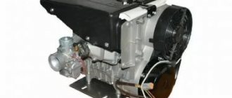
- drain the oil from the engine, then remove the engine and place it on some flat surface;
- remove the cooling casings and dynastrater;
- remove the final drive sprocket;
- loosen the clutch cover from the bolts and remove it;
- remove several clutch discs;
- after this it will be possible to easily remove the basket along with the chain and sprocket, the washer and the bushing;
- to disconnect the cylinder head, you need to unscrew the four washers that secure it; if there are noticeable burrs on the cylinder mirror, then it should be sharpened;
- remove the cylinder, remove the piston pin ring using pliers;
- unscrew the crankcase tightening bolts; an impact screwdriver can help, which is very useful in such cases;
- turn the engine to the disassembled side, gently hit it with a mallet until the crankcase separates into two equal halves;
- lay the engine straight, using a mallet, carefully knock out the driveshaft;
- After this, access to the bearings and seals appears.
Drive gear adjustment
To carry out the operation, use the original device A.95690, mandrel A.70184 or an analogue made according to the drawing.
The crankcase mating plane is positioned so that it assumes a horizontal position. Then an absolutely flat metal rod is installed on the bearing bed. The distance from the bar to the mandrel is measured by inserting the adjusting rings from the set into the gap under the bar in increments of 0.05. The measured value (crankcase base) is consistent with the correction applied to the drive gear. When assembling the unit, it is recommended to abandon the standard spacer sleeve to prevent repeated repairs. Instead, a non-deformable steel bushing 48 mm long is suitable (with a margin, shorten if necessary).
During turning, the parts control the force when turning the gear (should be 157–196 Ncm); for used bearings, a torque of 39.2–58.8 Ncm is valid. The use of a proprietary dynamometer 02.7812.9501 is not necessary.
Acceptable accuracy will be provided by a household steelyard. When working with it, you should wind one end of a 1 m long cord around the flange, and secure the other end to the scales. By pulling the device in a perpendicular direction, fix the turning torque. So, new bearings should provide 7-9 kg, and with mileage - 2-3 kg.
The process involves replacing the support washers with new ones - thicker than before. There are 7 standard sizes to choose from in increments of 0.05 mm within the range of 1.8-2.1 mm. Washer material – bronze or steel. In this case, the gears are installed tightly, but can be turned manually.
Tags: rear axle
Comments 9
universal joints and a smore shank then
Does the play appear when you release the clutch more sharply from the rear axle? Do you hear a blow? And when the clutch is softer, is everything good?
this is possible
very vague description of the problem. There are several places in the bridge where a gap may appear. Most often the spacer sleeve becomes loose. There are several reasons for this: defects, incorrect adjustments, and even the driver’s driving style. If the bushing is manufactured in violation of the technology, then it does not work with elastic deformation (spring-loading), but with simple deformation, which does not create the necessary tightening force for the nut, the bushing simply bends. If the cardan has wear on the crosspiece and vibration, then this vibration is transmitted to the flange, and it unscrews the shank nut, the bushing is not clamped between the ends of the bearings and rotates freely, wearing out its ends against the ends of the bearings. This bushing becomes unusable. tightening the nut will no longer help, but will harm the gearbox. If you move back abruptly (with axle box), or tow, moving backward (catching the cable to the front hooks), this accelerates the wear of the bushing. Often the gearbox hums just after such loads, the reason for this is deformation of the bushing and relaxation of the tension of the shank. The main pair may wear out. there will also be backlash. It happens that the splines on the axle shafts grind. there will also be backlash. you need to hang the wheels, disconnect the cardan and, by rocking the wheels or the shank flange, feel and listen for where there is play.
Not long ago, the rubber band on my jet rod burst and the bridge began to wobble. I removed and replaced the rubber bands, it will cost 100 rubles! Check all the rods with the installation tool!
Lateral clearance in GP and differential bearing preload
In accordance with the instructions, the lateral clearance and preload of the bearings are adjusted using tool A.95688/R.
In its absence, a caliper of a suitable size will perform the specified role.
To ensure the required preload, fix the distance relative to the bearing caps at the beginning of tightening and at the end. The required difference between the values is 0.2 mm.
The side clearance is adjusted by bringing the driven gear closer to the drive gear until it disappears. Initially, one of the nuts is in a loose position, the other (working) is tightened. After eliminating the gap, gradually tighten the attached nut until the jaws of the caliper move apart by 0.1 mm. The backlash adjustment stops when a slight knocking sound of the teeth appears. Next, both nuts are tightened evenly to a distance of 0.2 mm. The correctness of the work is indicated by uniform play in any position of the gears.
Front axle repair video
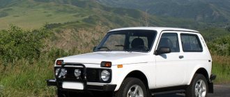
The front axle gearbox of the Niva VAZ-2121 car is removed for repair work, when it is necessary to correct the faults that we discussed in the article - “Features of the VAZ-2121 front axle”.
The work must be done on a lift or inspection pit.
We prepare the car for work.
We drain the oil from the front axle crankcase (see the article - “Changing the front axle oil”).
We dismantle the driveshaft (see the article - “Removing driveshafts”)
To do this, disconnect the lower left ball joint from the lever:
— hang out and remove the left front wheel;
— unscrew the adjusting nut of the front hub bearings;
1. Using a 22mm spanner, unscrew the nut securing the ball joint to the steering knuckle.
2. Place the stop under the lower arm and use a 13mm wrench to unscrew the 3 nuts on the bolts securing the ball joint to the lower arm, holding the bolts with a second wrench
3. Remove the bolts
4. Move the steering knuckle with the ball joint away from the lower arm
To do this, remove the left front suspension brace:
1. Using a 22mm wrench, unscrew the outer nut of the rear fastening to the body bracket
2. Remove the washer
3. Using a 19 wrench, unscrew the bolt of the front fastening of the brace to the cross member
4. Remove the front end of the brace from the cross member bracket and remove the brace
Hello! Nivovods constantly argue about the advisability of decoupling the front axle gearbox from the engine
. Opinions are opposite – from “must do” to “under no circumstances.” The arguments of opponents of the operation are simple: “The factory design is the most reliable.”
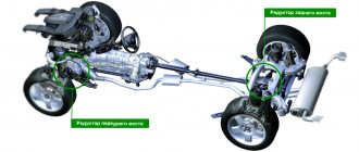
Proponents of the modification believe that decoupling the bridge reduces vibrations (and therefore extends the life of the gearbox), and makes it possible to painlessly produce suspensions for the axle shafts. In addition, on the later model the axle mount is independent
. I will not convince you of the benefits of this decision, or its negative consequences. I'll tell you how to do this job correctly.
The technology has been proven. On this model, the FRM (front axle gearbox) has an independent suspension as standard. To save time, you can purchase ready-made tying kits.
Many car enthusiasts make brackets and fastenings with their own hands, providing colleagues with drawings of their own design.
IMPORTANT! Such structural elements must be made of durable steel. It is unacceptable to use factory silumin elements as a platform for fastenings.
.
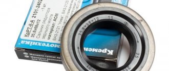
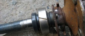
Changing the bearing
We prepare the bit, hammer, sealant and a special puller for the retaining rings, after that:
- Removing the wheels
- We take out the retaining ring from the bearing, to do this we take a wooden spacer and knock the bearing off the shaft with a hammer
- The wheel has an inner CV joint from which the oil seal must be removed
- We lubricate the working edge of the oil seal, and apply sealant to the outer part.
- We take a hammer and press the oil seal back into place, after which we install all the parts back.
The Chevrolet Niva front axle gearbox must be removed if repairs or replacement are necessary. In order to carry out all the necessary actions you need to have special equipment and certain skills. If the work is carried out in a garage, you may not achieve the desired results. Therefore, if you do not have experience in replacement, then it is advisable to contact specialists for a special service.
General rules for revision:
1. The untethered bridge must be fastened at three or four points that do not have a rigid connection with the engine. 2. The front axle beam and anti-roll bar are used as supports. 3. When determining the new position of the RPM, it is important to prevent horizontal displacement of the axes of the propeller shaft and axle shafts. The bridge can be uncoupled using a gearbox suspension kit from Chevrolet NIVA.
Therefore, most car owners prefer steel brackets made independently or in the factory. For cars taking part in off-road competitions, a version of the RPM steel body has been developed. This gearbox is structurally equipped with lugs for independent suspension. There are also additional subframes for extreme conditions of use of the NIVA. When installing the latter, the question: “how to untie the front axle” does not arise, since the gearbox is mounted in the subframe.
Sequence of work.
1. We purchase (make) a kit for untying. When making it yourself, we drill holes in the pallet in accordance
with the diameter of the studs. 2. We securely install the car on supports, preferably above the inspection hole. 3. Drain the oil from the gearbox. 4. We dismantle the CV joint drives, having first freed the steering knuckles of the wheels. 5. Disconnect the front driveshaft from the flange. 6. We remove the axle gearbox from under the car. 7. On a flat working surface, separate the bottom tray and side covers of the RPM. 8. On top of the CV joint drive covers, using elongated studs, screw the earring brackets. It is possible to replace the installation sequence of covers and brackets, depending on the kit you choose.
9. Instead of a standard pan, we attach a reinforced one, with installed clamps for attaching the anti-roll bar to the beam. In addition to the factory gasket, we use sealant. The pallet will experience additional loads, so the tightness needs to be improved. 10. We hang the RPM with the rear mount on the stabilizer beam. We center the axis of the propeller shaft and the axis of its flange in the gearbox. 11. On the bridge beam we mark the fastening eyes for the brackets for the front suspension of the gearbox housing. 12. We weld the eyes to the bridge beam and perform anti-corrosion treatment. 13. We fix the earrings in the eyes using polyurethane or rubber silent blocks. 14. Check the vertical
.
15. Attach the axle shafts and driveshaft, secure the steering knuckles. 16. Fill the gearbox with oil according to the operating instructions. 17. Without starting the engine or removing the car from its supports, check the free rotation of the wheels and front driveshaft
. 18. We make a test drive, after which we re-inspect the car in the inspection pit.
Front gearbox
The need to remove this part of a NIVA car usually arises if signs of a malfunction appear and the part needs to be repaired or replaced. When disassembling, assembling or repairing a gearbox, it is necessary to use specialized equipment. Relevant skills are also required. If necessary, it is better to contact a car repair shop.
Removing the front axle
First, the NIVA is driven onto a lift or inspection pit, and the gearbox can be disassembled and dismantled. Removed:
- Stabilizer bar;
- Engine crankcase protection plate;
- Suspension cross member extensions.
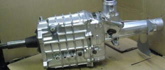
Gearbox for VAZ Niva
Work continues:
- The shock absorbers are disconnected from the lower suspension arms;
- The drive gear flange is disconnected;
- The Chevrolet front driveshaft is removed;
- The suspension spring is compressed, separate the ball joint and the lower arm;
- Remove the spring;
- Disconnect the steering linkages and steering linkages.
- Remove the cap;
- Unscrew the bearing nut from the wheel hub.
On the other side of the NIVA car suspension, all operations are performed in the same sequence. Then you need to perform the following steps:
- The clamp that tightens the connection between the muffler pipe and the exhaust pipe is loosened;
- The suspension of the mufflers with pipes on the gearbox is disconnected;
- The nuts holding the exhaust pipe of the mufflers going to the exhaust manifold are unscrewed;
- Remove the pipe downwards;
- Unscrew the nuts that secure the cross members of the pillow suspension to the brackets;
- Unscrew the bolt that secures the right bracket to the engine;
- The front axle is supported, the nuts securing it are unscrewed;
- The Chevrolet engine is raised by 25-30 mm;
- The axle and front wheel drives are removed.
Gearbox Niva
Repair of the front axle assembly
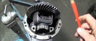
Disassembly is carried out in the following sequence:
The front axle is installed and secured on a stand intended for repair work; The plug opens and the oil is drained from the Chevrolet crankcase; Unscrew the nuts securing the inner hinge housing of the bearing cover; The hinge is removed very carefully (so as not to damage the sealing gasket); Remove the retaining ring with the spring washer; Press the bearing from the inner joint housing; Remove the oil seal; The stamped cover and sealing gasket of the axle housing are removed (the bottom cover cannot be removed); The front axle gearbox is disassembled
Front Unit Installation
The installation of the bridge on the NIVU occurs in the reverse order of removal. During the installation process, the gearbox is placed in place. Bolts and nuts must be tightened to torque values. Transmission oil is poured into the front axle housing through the oil filler hole. Oil should not go over the bottom edge of the hole.