Good visibility is essential for safe vehicle operation. In the autumn-winter period, changes in air temperature cause the windows to fog up, and visibility through them deteriorates. The issue of glass transparency is especially relevant at night, when visibility is already poor.
An effective way to combat fogging of car windows is to heat them. The windshield is usually heated by directed flows of warm air. The rear window and door mirrors are usually heated electrically. Conductive tracks made of high-resistivity metal in the form of thin ribbons are applied to the surface of the glass on the side of the car interior. When electric current passes through them, thermal energy is released. The glass heats up and the water evaporates. After a few minutes the glass becomes transparent.
Electrical diagram for connecting the heater
To successfully diagnose and repair the rear window heating system of a car at a professional level, you need to know the electrical connection diagram of the heater and understand the principle of its operation.
The photo shows a typical diagram for connecting a car's rear window heater to the on-board electrical wiring. Let's consider the principle of its operation.
The supply voltage from the positive terminal of the battery through the ignition switch and fuses is supplied to the heater switch and to the 30 (or 87) power contact of the relay. The negative terminal of the battery is connected to the car body, one of the glass heater terminals is also connected to the body. When you press the heater power button, voltage is applied to the relay winding, the relay is activated, the power contacts close and connect relay terminals 30 and 87 to each other. The current enters the heater, flows through a group of parallel-connected filaments and returns through the car body to the negative terminal of the battery.
Rear window defroster malfunctions
The operation of the rear window defogger is not paid attention to until the glass fogs up or becomes covered with frost. After turning on the heater, it suddenly turns out that after a few minutes the glass did not become transparent or visibility appeared only through part of the glass. Depending on the external manifestation, even without measuring instruments, one can immediately make an assumption about the cause of the failure.
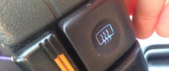
Please note that the heated rear window and rear view mirrors of the vehicle can only be turned on when the ignition key is turned to the ON position. In some car models, the heater can only be turned on when the engine is running. This is done to prevent severe battery discharge, since the rear window heater, depending on the car model, consumes a current of 10 A to 25 A. For comparison, one car headlight consumes a current of only 5 A.
The heater does not turn on
If the indicator on the button for turning on the heated rear window does not light up after pressing it, then most likely the fuse has blown or the button itself is faulty. If the indicator lights up, but not a single thread heats up, then the cause of the malfunction may be the relay or connectors connecting the heater to the electrical wiring. In this case, using the documentation for a specific car model, it is necessary to determine the location of these parts and replace the one that failed. It is not always possible to quickly find the installation location of the relay, but there is a way to check its serviceability indirectly, which will be discussed below.
The glass is slowly fogging up
Sometimes there is a case when, after turning on the heater, the glass fogs up for a time significantly exceeding several minutes. In this case, if it is not very cold outside, the reason may lie in poor contact of one of the connectors of the electrical circuit. As a result, the contact resistance increases, the current is limited, and as a result, the power released on the glass heater filaments decreases. To check such a malfunction, it is necessary to measure the voltage at the input terminals of the heater and battery using a DC voltmeter (multimeter or pointer tester turned on in the DC voltage measurement mode). The voltages should not differ by more than one volt.
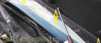
Horizontal streaks of fog remain on the glass
And finally, the most common case of malfunction of the rear window heating system of a car is the breakage of one or more heater threads applied directly to the glass. This type of malfunction is immediately visible by the horizontal stripe of remaining fog on the glass after turning on the heater.
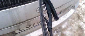
The conductive tracks on the rear window have low mechanical strength and are easily destroyed when exposed to impact. Therefore, it is prohibited to remove frost and ice from glass using a scraper. Only wipe with a soft cloth is allowed. It is also necessary to ensure that when transporting long items they do not rest against the rear window. As a rule, individual heater filaments stop working as a result of their accidental mechanical destruction. In the area of the damaged thread, after turning on the heating, streaks of sweat or frost remain.
When renovating an apartment, I was transporting floor skirting boards in my car and did not notice how one of them rested against the rear window. After a while, when I needed to warm up the rear window, I saw the result of my carelessness. The two heater strips running through the middle of the glass did not heat up, which significantly impaired the view of the road. Upon visual inspection, one gap of about 1 mm wide was found on the non-functioning strips, as in the photograph. The question arose about the need to repair the rear window defroster.
How to find the location of a broken glass heating filament
It is not difficult to determine which heater thread is broken, since in the area where it passes, fogging does not disappear when the heater is operating. Therefore, in order to easily find the faulty thread during repairs, it is advisable to count the threads from top to bottom and remember which one is by number in the break, so that later, by visual inspection, try to find the place of its damage. But the thread break is so small that it is impossible to visually find it. Then a DC voltmeter, ohmmeter or voltage indicator will help in your search. To quickly find the location of a malfunction in a heating element, you need to understand how it works and works.
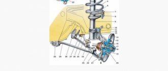
The design of the heating element of the glass heating system
The logical question is, why does it happen that only one or several threads in the heater do not work, while the rest work? To answer this question, you need to familiarize yourself with the design of the heating element.
The heating element of the rear window of a car is designed as follows. On the sides of the rear window there are two conductive busbars 1 and 2. Threads made of high-resistivity material are connected to these busbars. Each thread has a resistance of about 10 ohms. The number of threads depends on the height of the glass. Thus, each thread is a separate heating element, the operation of which does not depend on the others. A parallel connection scheme of heating elements is used. This circuit design ensures high operational reliability of the heater, since the break of one or more threads does not lead to a complete stop of its operation.
Finding a broken heater filament using a voltmeter
To work, you will need any DC voltmeter with a measurement limit of 15 V. Any pointer tester or digital multimeter will be suitable as a voltmeter. Before starting work, you need to turn on the heater.
Since one of the heating element busbars is connected to the car body, the negative terminal of the voltmeter can be connected to the car body; any screw or bolt screwed directly into the body will do. The most convenient way to connect to the trunk lid lock bracket is with an alligator clip.
Since it is difficult to visually determine whether the heater is heating with transparent glass, touching the positive probe of the voltmeter to bus 1, and then to bus 2, you will immediately understand this. There should be a voltage of +12 V on bus 1, and 0 V on bus 2. It is quite possible that the left bus in your car will be connected to ground, and the supply voltage will be supplied to the right bus. If there is no access to the tires, then measurements can be taken by touching with a probe any of the threads at the points of connection with the tires, that is, at the points where they exit the rubber seal. In the photo these are points 1 and 5.
Using a voltmeter it is easy to determine which part of the heating system is faulty. If the heater is turned on, the power indicator on the button lights up and there is 12 V on bus 1, but there is no heating, which means that the electrical wiring to bus 1 is working. If there is no voltage on bus 1, then there is a bad contact in the supply voltage terminal on bus 1, or the relay is faulty. If 12 V is present not only on bus 1, but also on bus 2, then you need to look for a bad contact in the terminal connecting the wire to bus 2 or the circuit connecting the wire to the vehicle ground.
Finding the location of the thread break
After checking the supply voltage supply system to the heater, you can begin to determine the location of the heating filament break. The thread is a tape resistance of about 10 ohms, and therefore the voltage at different points has different values. Therefore, at point 1 the voltage will be equal to 12 V, at point 3 - 6 V, and at point 5 - 0 V. Therefore, even without knowing which thread is broken, it can be easily found by measuring the voltage value at the midpoints of the length of all threads. On broken threads, the voltage will be 12 or 0 V. If the voltage is 12 V, then the break point is on the left, and if 0 V, then on the right.
Now it is enough to slowly move the probe towards the break, in the place of a sharp change in voltage there will be a break. For example, in the photograph this is the section of thread between 6 and 7 points.
Finding a broken thread using an ohmmeter
Using a multimeter or pointer tester in resistance measurement mode, you can also successfully find the location of the thread break. There is no need to turn on the heater when searching with an ohmmeter, but it will not be possible to check the serviceability of the supply voltage supply system to the heater, except for checking the ground connection circuit.
If the broken thread is not known, then you need to connect one end of the ohmmeter probe to the ground terminal, and touch the middle of the heater threads with the other end in turn. The thread on which the ohmmeter will show resistance is twice as high and will be broken. For reference, the resistance on whole threads relative to bus 1 or 2 should be 2-3 ohms. In case of a break in the thread, the ohmmeter will show 4-6 ohms.
When a damaged thread is found, you need to move the end of the probe from the center in any direction. If the resistance increases as the probe moves towards bus 1, then the break is located between bus 1 and the point of contact of the probe. For example, in the place indicated by points 1 and 2. As soon as the probe passes the break point, the resistance will sharply decrease several times. If the resistance decreases, it means that the place where the thread breaks is located between the probe and bus 2. For example, in the place indicated by points 3 and 4. Then you need to move the probe towards bus 2, and when the resistance drops sharply, the break point will be at this point .
Finding the location of a broken thread using an Automotive Probe Tester
If you don’t have a voltmeter or ohmmeter, you can find where the heating element filament breaks using a homemade automotive tester-probe, consisting of just one LED and a current-limiting resistor. I made such a tester for myself a long time ago, although I have any measuring instruments at my disposal. A homemade car tester is always in the glove compartment of my car and I have had to use it more than once.
Finding the location of a broken thread using a probe tester is not much different from searching with a voltmeter. In this case, the indicator will not be an arrow or numbers, but the glow of an LED.
Before you start searching for a damaged thread with a probe, you must apply supply voltage to the heater. First, the presence of voltage on bus 1 is checked, the LED should light up, if the LED does not light up, then the fault lies in the supply voltage supply circuit. Next, the voltage on bus 2 is checked; the LED should not light up; if it lights up, it means there is a contact failure at the point where the wire is connected to the bus or the car body.
To find where the heater filament is broken, you need to slowly, lightly touching the filament, move the tip of the probe along it. At the point at which the LED goes out or lights up there is a thread break. For example, at point 6 the tester LED will light up, but at point 7 it will not. In my case, the thread breaks were large and the tester was only useful for checking the quality of the repair.
Additional tips and tricks
Today, many effective compounds are known that can be used to repair heating filaments. It is permissible to use BF-2 or BF-6 glue as a base. It is also allowed to use other substances that dry quickly. Paint, enamel, and polymer resin are often used for this purpose. To make a conductive paste from the listed materials, you should add small shavings to it. This substance can be obtained from a small file. You can also take brass, aluminum or copper.
After combining the ingredients, it is recommended to apply them to the prepared surface. To do this, you should use a homemade stencil. It can be easily done using electrical tape. It is also permissible to use construction tape for this purpose. In terms of effectiveness, homemade glue is not inferior to ready-made compounds. It is also permissible to solder the area of damaged thread or disconnected terminal. This procedure cannot be carried out if the distance between the thread fragments exceeds 2 millimeters. First, the electrochemical method is used.
When eliminating contact breakdowns, soldering is considered a more effective and reliable method. It is performed using a standard method, which involves the use of flux and solder. Flux should be used like FCA. It should be made on the basis of zinc chloride. POS-18 or similar is used as solder.
An effective repair method is electrolytic coating. This procedure will require a liquid based on copper sulfate. It is recommended to add 2 small spoons of copper sulfate to 100 milliliters of water. It is also possible to add battery electrolyte to the composition - just a few drops.
In addition, you will need to prepare a copper wire with a cross-section of 6 square millimeters. A prototype of a copper brush is made from wire. Then the stripped conductor, wrapped in rags and thread, should be connected to a power source. This is done with the opposite end of the wire. In this case, the negative of the battery is connected to the body. The brush should be moistened in an electrolyte solution and carefully moved in the area where the thread breaks. Little by little, the treatment area will become covered with copper particles. This occurs due to the process of electrolysis.
Methods for repairing heating element filaments
There are several ways to restore the functionality of a heating filament at home.
Using conductive pastes and adhesives
The easiest and most effective way is to use special repair kits, such as DONE DEAL DD6590, designed to repair rear window defroster threads and contacts by both amateurs and professionals. The good thing about this method is that it does not require tools or materials. It is enough to apply a little conductive paste from a syringe to the site of the thread break according to the attached instructions, wait until the paste hardens and the repair is completed. But this set costs more than $15.
The second method is similar to the previous one. But instead of a proprietary set, they use purchased conductive adhesives, for example, Elekont, a Moscow manufacturer. Glue is applied to the place where the thread breaks, overlapping the entire part of the thread by a centimeter on each side. To obtain a neat look, use a stencil made of electrical tape or adhesive tape. For reliability, the glue is applied twice. It is advisable to lay a piece of tinned copper wire with a diameter of 0.3-0.5 mm between the layers of conductive glue.
There is an opinion that conductive paste or glue for repairing glass heater filaments can be made independently by mixing paint or glue with brass filings in a one-to-one ratio. The resulting composition is applied in a thin layer through a stencil to the place where the thread breaks in several layers. But the reliability of this technology has not been confirmed by practice.
Electroplated copper deposition
Another method is galvanic copper deposition. The heater filament repair method seems attractive. But from personal experience I can say that the reliability of such coatings at home is low. So I was hesitant to use this technology.
Using soft soldering
A mechanical method of restoring the integrity of the rear window heater filaments, using soft soldering, has become widespread. I tested the reliability of this method when repairing rear window heating filaments in my own car. The step-by-step instructions below, written based on my experience, will allow you to easily repair the heater filament yourself in just a few minutes, with virtually no financial costs.
On the advice of theorists on the Internet, I made a big mistake and tried to clean the thread with sandpaper. As a result, instead of a break in the thread 1 mm wide, there was a break larger than 1 cm. The thread strip is very thin, only a couple of tens of microns, and can be erased instantly even with the finest-grained sandpaper. The heater threads are already not covered with anything, and it is enough to degrease the soldering area using a rag soaked in alcohol or acetone.
If the width of the thread break is less than 1 mm, then you can do without soldering an additional conductor. In my case, the width of the gap was large, and I had to first prepare a piece of copper wire for the jumper. A current of about 1 A flows through one thread of the heater. Based on this, we select a wire with a cross section of 0.17 mm2 from the wire cross-section table, which corresponds to a diameter of 0.45 mm. The length of the copper jumper must be equal to the width of the thread break plus 2 cm. Before soldering, the jumper must be tinned with a thick layer of POS-61 tin-lead solder. There is no need to tin the heater thread.
In order for the solder to reliably adhere to the heater thread, before soldering the jumper, you need to lubricate the thread in the soldering zone with a thin layer of zinc chloride flux using a brush.
Next, the jumper is pressed against the heating thread and heated for one second with a 12 W soldering iron. The hand is moved to the side. The jumper should be held on by a thread. Trying to tug it to check the quality of soldering is unacceptable; it will fall off and also tear off a piece of the heater thread. Unfortunately, this has been verified empirically. As a result of experiments, I eventually had to solder a jumper 5 cm long.
After soldering one end of the jumper, the second is pressed tightly to the thread and is also heated with a soldering iron. After soldering is completed, in order to remove residual acid flux, the glass is thoroughly washed with water.
To top it off for reliability, although this is not necessary, I covered the soldered jumper on top with transparent “Moment” superglue based on cyanoacrylates, the heat resistance of which is about 70°C. The heater does not heat up above this temperature.
As a result, the time to repair a broken thread with your own hands, taking into account all the preparatory work, was no more than ten minutes. The repaired threads have been in service for more than three years.
DIY conductive glue
To repair the glass heating circuit, it is not necessary to purchase special compounds. You can make conductive glue with your own hands. For this we need:
- Superglue and aluminum shavings. To obtain a conductive material, mix the shavings with glue in a 1:1 ratio.
- Nail polish, silver and graphite powder. Pour 2 types of powder into a bottle of varnish and mix with a toothpick.
- Epoxy resin and copper shavings. Mix epoxy polymer with shavings in a ratio of 5:1. Before application, add an amine component to harden the resin.
- Tsaponlak and graphite powder. Graphite powder can be obtained by grinding the battery core. Mix ingredients 2:1.
Graphite powder can be obtained from the lead of a simple pencil.
We recommend watching the video instructions: