The ECU on the UAZ Patriot controls engine operation based on indicators received from sensors. The reliability of starting the power unit and fuel consumption depend on the correct functioning of the unit. The plant used several types of controllers depending on the motor model, year of manufacture and compliance with Euro environmental standards, differing in connectors and characteristics.
The UAZ Patriot ECU controls the operation of the engine.
What is an ECU on a UAZ Patriot?
An electronic control unit, or ECU, located in the engine compartment, adjusts the mixture composition to maintain a stoichiometric ratio (the volume of oxidizer corresponds to the norm for fuel combustion).
The controller is connected to the electrical wiring harness and receives power from the on-board network: the unit is turned on when the key is turned in the ignition switch.
A microprocessor and a memory module are installed inside for storing firmware (mapping the operation of the power unit depending on external weather factors, fuel quality and engine condition).
Control unit functionality
The controller provides:
- adjustment of ignition timing;
- changing the composition of the air-fuel mixture depending on the engine temperature and signals from the oxygen sensor on the UAZ Patriot;
- idle mode support;
- shutting off the fuel supply when the maximum permissible rotation speed is reached;
- fixing errors with the inclusion of the Check Engine indicator.
What sensors does it control?
The controller receives information from sensors:
- antifreeze temperature;
- oxygen concentrations before and after the neutralizer;
- mass air flow;
- throttle and accelerator pedal positions;
- movement speed;
- rotation speed and position of the crankshaft;
- intake air temperature;
- voltage in the on-board network;
- detonation combustion.
The controller receives information from various sensors.
The signals are processed by a microprocessor, which adjusts the operation of the fuel injectors and dynamically adjusts the ignition timing. As the cooling jacket warms up, the unit sends a command to turn on the fan on the radiator.
The controller detects the detonation combustion process and tries to eliminate the malfunction by changing the composition of the mixture and the timing of the spark.
ECU pinout Mikas 12.3
| 48-pin block | |
| A1 | Injector 4 control (-) |
| A2 | Injector 2 control (-) |
| A3 | Injector 3 control (-) |
| A4 | Injector 1 control (-) |
| B1 | Heating control DK2 (-) |
| B2 | Canister purge valve (-) |
| B3 | Heating control DK1 (-) |
| B4 | DTOZH signal input |
| C1 | |
| C2 | ETC position sensor input 2 |
| C3 | ETS position sensor input 1 |
| C4 | Power supply for sensors 5B (DND, MAF/DAP) |
| D1 | Analogue mass GNA (ETC, DTOZH) |
| D2 | K-Line 2 (immobilizer) |
| D3 | Knock sensor weight |
| D4 | ETC sensor power supply 5V |
| E1 | Oxygen sensor 1 weight |
| E2 | Oxygen sensor 1 signal |
| E3 | Knock sensor signal input |
| E4 | Reserve entrance |
| F1 | Oxygen sensor 2 weight |
| F2 | Oxygen sensor 2 signal |
| F3 | Reserve entrance |
| F4 | DBP input |
| G1 | Total mass of DPRV, screen DK1/2, DPKV, DD |
| G2 | Rough Road Sensor (RSD) |
| H1 | Analog mass (DBP, DND) |
| H2 | DTV signal input |
| H3 | Reserve entrance |
| H4 | ETS motor control (-) |
| J1 | DPRV signal input |
| J2 | DPKV (+) |
| J3 | DPKV (-) |
| J4 | ETS motor control (+) |
| K2 | Reserve output |
| L4 | Ignition weight |
| M2 | Ignition coil 2-3 |
| M4 | Ignition coil 1-4 |
| 32-pin block | |
| A1 | Fan relay control 1 (-) |
| A2 | Starter relay control (-) |
| A3 | Diagnostic lamp |
| A4 | Signal to tachometer |
| B1 | Main relay control (-) |
| B2 | Signal to the TOZ indicator |
| B3 | Clutch sensor signal (+) |
| B4 | Fuel pump relay control (-) |
| C1 | Air conditioning relay control (-) |
| C2 | Stop lamp signal (+) |
| C3 | Brake sensor signal (+) |
| C4 | Ignition switch terminal 15/1 |
| D1 | Reserve input (+) |
| D2 | Request to turn on the air conditioner (+) |
| D3 | Fuel level sensor (reserve) |
| D4 | Accelerator pedal sensor 2 ground (pin 5) |
| E1 | 5V accelerator pedal sensor 2 (pin 2) |
| E2 | Accelerator pedal sensor 2 (pin 6) |
| E3 | CAN-L |
| E4 | Accelerator pedal sensor 1 ground (pin 4) |
| F1 | 5V accelerator pedal sensor 1 (pin 1) |
| F2 | Accelerator pedal sensor 1 (pin 3) |
| F3 | CAN-H |
| F4 | K-Line |
| G1 | Speed signal input, pulse/m |
| G2 | +12 non-disabled |
| G3 | Filling limit switch / door sensor |
| G4 | Weight of output stages |
| H3 | +12 after GR |
| H4 | Reserve output |
You can download the archive with all the diagrams from the link.
Typical parameters of Patriot ECU
The controller memory contains firmware with typical parameters describing the functioning of the sensors and the engine in normal mode. When the software is refined, the data is adjusted, which makes it possible to increase power or torque to the detriment of other characteristics (for example, increasing exhaust toxicity by turning off feedback from the oxygen concentration sensor). The setup is carried out by private laboratories that offer their own firmware versions to UAZ Patriot owners.
Why do you need to know the pinout?
Diagnostics of an injection engine begins mainly by reading error codes from the controller’s RAM. Most diagnosticians, I’m talking only about those with whom I had to communicate, based on these errors, change the sensor and if this does not help, they simply send it to an electrician, citing a wiring fault. You should avoid such diagnosticians, and if you are engaged in diagnostics yourself, then do not imitate them.
In fact, checking the serviceability of the wiring is quite simple if you have a Mikas 7.1 pinout (pin assignment) of the controller connector and have a multimeter. As a last resort, you can use a control llama, but this is not entirely convenient. How to find the fault yourself can be found in the article “Diagnostics 406 engine” by selecting the appropriate fault.
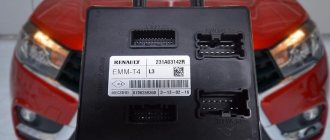
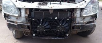
ECU appearance
The product has a stainless steel casing that protects the electronics from mechanical damage, high temperatures and moisture. The body has lugs for mounting on the wheel mudguard. Connection to the on-board network is made via a plastic connector. On the outer part of the casing there is an information label indicating the unit model, date of manufacture, serial number and a number of technical parameters.
The appearance of the ECU protects the electronics from mechanical damage.
Replacing the UAZ Patriot ECU
If inspection of the printed circuit board shows irreversible damage to the electronic components or repairs are considered uneconomical, then you should purchase a controller of the same model. Installation of the product is carried out in the reverse order; it is necessary to tightly fasten the locking lever of the electrical wiring harness. Depending on the year of manufacture, different firmware versions are used, differing in motor mapping.
If malfunctions occur or increased fuel consumption occurs, the unit must be reprogrammed.
Pinout Mikas 7.1 injector and carburetor
This block is designed to control internal combustion engines:
- ZMZ-4062.10—with gasoline injection and electronic control;
- ZMZ-409.10—with gasoline injection and electronic control;
- ZMZ-405.10—with gasoline injection and electronic control;
- ZMZ-4063.10—carburetor, with electronic ignition system;
- ZMZ-4061.10—carburetor, with electronic ignition system.
- UMZ-4213.10—with gasoline injection and electronic control;
- UMZ-420.10—with gasoline injection and electronic control.
The block is a multi-mode cyclic machine with an extensive program that provides registration and processing of information from the system sensors to control the actuating electric mechanisms of the engine. The block is implemented on the basis of an 8-bit microcontroller and on an imported element base, has a monoblock single-board design with a 55-pin electrical connector from AMP.
| 1 | white | Ignition coils 1 and 4 (KZ/1-4) Ignition control circuit. Creates excitation in ignition coils 1 and 4. |
| 2 | black White | Grounding the control unit. (General GNI) The contact is connected to the vehicle ground. The voltage at the contact relative to ground should be close to zero. |
| 3 | white/green | Fuel pump relay (FPR) Control of the fuel supply system relay. Turning on the ignition is a signal for the control unit to connect power (+12 V) to the fuel supply system relay. If there are no crankshaft position reference signals, the control unit turns off the relay. When the reference signals of the position of the k.v. are resumed. the unit turns on the fuel pump relay again. |
| 4 | blue/cyan | Additional air regulator* (РДВ/1) |
| 5 | Not used | |
| 6 | White black | Input signal from the mass air flow sensor “-” (MAF) |
| 7 | black/yellow | Input signal from the mass air flow sensor “+” (MAF+) |
| 8 | pink | Input signal from the camshaft position sensor “+” (DPRV +) |
| 9 | Not used | |
| 10 | Not used | |
| 11 | green/white | Knock Sensor Input Signal "+" (DD+) The signal is the voltage supplied to the control unit from the knock sensor to detect knock. The block adjusts the ignition timing depending on the level of detonation to extinguish it |
| 12 | White yellow | Power output of the throttle position sensor (TPS (power) |
| 13 | brown | L - diagnostic line (L - Line) |
| 14 | black | Control unit grounding (Common GNP) The contact is connected to the vehicle ground. The voltage at the contact relative to ground should be close to zero. |
| 15 | Not used | |
| 16 | pink/green | Nozzle 2(F/2) |
| 17 | orange | Injector 1 (F/1) Injector control. The voltage at these contacts is supplied through injectors connected to +12 V. When the ignition is on and the engine is not running, the voltage at the contacts is equal to the battery voltage. At idle, the charging system increases this voltage slightly. At higher engine speeds or greater engine load, the increased frequency and duration of the injector injection pulse causes a slight decrease in voltage compared to the idle voltage. |
| 18 | blue | Battery terminal 30 + 12 V ( 30 ) Provides constant +12 V power to the electronic unit, including when the ignition is turned off. The voltage comes through the fuse. |
| 19 | blue red | Common (Common GNO) The contact is connected to the vehicle ground. The voltage at the contact should be zero. |
| 20 | brown/white | Ignition coils 2 and 3 (KZ/2-3) Ignition control circuit. Creates excitation in ignition coils 2 and 3. |
| 21 | Not used | |
| 22 | pink/blue | Diagnostic lamp (LD) Control of the diagnostic lamp. The electronic unit provides ground for turning on the diagnostic lamp. With the ignition on and the engine not running, the lamp should light up for 0.6 s and go out, and the voltage at the contact relative to ground should be close to zero. When the lamp is turned on, this voltage matches the battery voltage. |
| 23 | Not used | |
| 24 | red/pink | Control unit grounding (General GNI) The contact is connected to the vehicle ground. The voltage at the contact relative to ground should be close to zero. |
| 25 | Not used | |
| 26 | yellow/black | Additional air regulator (RDV/2) |
| 27 | orange/white | Ignition switch, terminal 15 (15) “On” signal to the control unit from the ignition switch circuit. The signal does not power the unit, it signals to it that the ignition is on. The voltage is equal to the battery voltage when the ignition switch is in the ignition or starter position. |
| 28 | Not used | |
| 29 | Not used | |
| 30 | Red Green | Common sensors (General GNA) The contact is connected to the vehicle ground. The voltage at the contact relative to ground should be close to zero. |
| 31 | yellow/white | Control channel for the burn-in of the mass air flow sensor (burn-in of the mass air flow sensor) |
| 32 | Not used | |
| 33 | Not used | |
| 34 | orange/red | Nozzle 4(F/4) |
| 35 | yellow green | Injector 3 (F/3) see pins 16 and 17. |
| 36 | measles h/blue and | Input signal from CO adjustment potentiometer (PTSO +) |
| 37 | orange/green | Input+12V(12) |
| 38 | Not used | |
| 39 | Not used | |
| 40 | Not used | |
| 41 | Not used | |
| 42 | Not used | |
| 43 | blue/black | Output signal (logic level) to tachometer |
| 44 | white/pink | Input signal from intake air temperature (IAT) sensor |
| 45 | White blue | Input signal from the coolant temperature sensor (DTOHL) The electronic control unit sends a 5 V signal to the coolant temperature sensor, which is a thermistor. The sensor, also connected to ground, changes the voltage depending on the temperature of the coolant. |
| 46 | white/brown | Main relay (RGL) |
| 47 | Not used | |
| 48 | yellow/blue | Input signal from the crankshaft position sensor “-” (DPKV -) |
| 49 | white/blue | Input signal from the crankshaft position sensor (Dpkv+) The contacts provide the electronic unit with data on the speed and position of the crankshaft. With the ignition on but the engine not running, the voltage should be below 1V. As the crankshaft rotates, the voltage increases with increasing speed. |
| 50 | Not used | |
| 51 | Not used | |
| 52 | Not used | |
| 53 | green | Throttle Position Sensor + Input (TPS+) The input voltage of the throttle position sensor, which corresponds to actual changes in throttle position, varies from 0 to 5 V. Typically, the voltage at idle speed is below 1 V, and with the throttle fully open it is 4.4...4.7 V. |
| 54 | Not used | |
| 55 | Red Blue | K - diagnostic line (K-Line) This line communicates with diagnostic equipment (tester, stand, etc.) |
UAZ Patriot ECU pinout
The following controllers were installed on UAZ Patriot cars with gasoline engines:
- from the Russian company Itelma (Mikas models of different generations, differing in pinout and electronics characteristics);
- from the German manufacturer Bosch, which supplies components to automotive concerns around the world.
“Mikas-5”
“Mikas-5” contains 19 contacts.
The block is equipped with a block with 55 pins (the top row contains 19 contacts), the purpose is indicated in the table in rows, starting from the top strip, from left to right.
| Position | Purpose |
| 1 | Ignition coil of cylinders 1 and 4 |
| 2 | Ignition circuit |
| 3 | Fuel pump relay |
| 4 | Air pressure regulator |
| 5 | – |
| 6 | Mass air flow sensor (negative signal) |
| 7 | Mass air flow sensor (positive signal) |
| 8 | Phase sensor |
| 9 | – |
| 10 | – |
| 11 | Knock warning switch |
| 12 | Throttle position sensor |
| 13 | Diagnostics (L-contact) |
| 14 | Power input |
| 15 | Formation of the FVN |
| 16 | Injector 2nd cylinder |
| 17 | Injector 1st cylinder |
| 18 | Signal via pin 30 from battery |
| 19 | Power cable |
| 20 | Ignition coil for cylinders 2 and 3 |
| 21 | – |
| 22 | Check Engine |
| 23 | – |
| 24 | Signal from the ignition switch |
| 25 | Air conditioner control |
| 26 | Air pressure regulator |
| 27 | Signal from connector 15 in the ignition switch |
| 28 | – |
| 29 | – |
| 30 | Common sensor circuit |
| 31 | Burning the air flow sensor |
| 32 | – |
| 33 | – |
| 34 | Injector 4th cylinder |
| 35 | Injector 3rd cylinder |
| 36 | Carbon monoxide adjustment potentiometer |
| 37 | Positive signal from main relay |
| 38 | – |
| 39 | – |
| 40 | Request to the air conditioning compressor |
| 41 | – |
| 42 | – |
| 43 | Engine speed |
| 44 | Air temperature |
| 45 | Antifreeze temperature |
| 46 | Main relay power supply |
| 47 | Pressure sensor power supply |
| 48 | Shaft speed sensor negative signal |
| 49 | Shaft speed sensor positive signal |
| 50 | Pressure sensor power supply |
| 51 | – |
| 52 | – |
| 53 | Throttle position sensor |
| 54 | – |
| 55 | Diagnostics (K-contact) |
“Mikas-7.1” (injection or carburetor)
Universal type controller for 16-valve ZMZ engines (with injection and carburetor). The pinout is the same as on Mikas-5. But the unit does not have backup terminals that are needed for the exhaust gas emission control system. The purpose of the remaining contacts does not differ from the Mikas-5 pinout (the blocks are built on the basis of a unified printed circuit board and connector). On UAZ vehicles there are “Mikas-7.2”, which differ in firmware and are adapted for the ZMZ-409 and UMZ-4213 engines (they differ in the product number).
“Mikas-7.1” is universal.
The pinout of additional contacts in Mikas 7.1 from the top row from left to right is shown in the table.
| Number of the involved backup contact | Purpose |
| 5 | Canister cavity purge valve |
| 9 | Driving speed sensor |
| 10 | Oxygen concentration sensor before the neutralizer (minus) |
| 21 | Formation of the FVN3 signal |
| 23 | Exhaust gas recirculation valve |
| 28 | Oxygen concentration sensor before the neutralizer (plus) |
| 29 | Formation of the FVN2 signal |
| 38 | Anti-slip controller |
| 39 | Oxygen concentration sensor after the neutralizer (minus) |
| 41 | Knock detection sensor (secondary) |
| 42 | Controller programming |
| 51 | Diagnostics of the FVN system |
| 52 | Formation of the FVN4 signal |
| 54 | A sensor that determines the degree of opening of the exhaust gas recirculation valve. |
"Bosch"
“Bosch” has 2 blocks of 56 contacts.
The Bosch ME17.9.7 controller, found on the Patriot (complies with Euro-3 standards), has 2 blocks of 56 contacts each, the purpose of which is indicated in the table (from left to right from the bottom row).
| Position | Left plug | Right plug |
| 1 | Crankshaft position | – |
| 2 | Lambda probe | – |
| 3 | Throttle position | – |
| 4 | DK1 | – |
| 5 | DT coolant | Gas pedal |
| 6 | DK2 | Likewise |
| 7 | Minus throttle position sensors | Refrigerant pressure sensor |
| 8 | – | – |
| 9 | – | – |
| 10 | – | – |
| 11 | – | Accelerator |
| 12 | – | – |
| 13 | Shaft angle sensor | – |
| 14 | – | – |
| 15 | DT coolant | Main relay |
| 16 | – | Ignition (plug 15) |
| 17 | – | – |
| 18 | – | – |
| 19 | – | – |
| 20 | Throttle sensor | – |
| 21 | – | Gas sensor |
| 22 | – | Fan Drive Test |
| 23 | Throttle sensor power supply | – |
| 24 | – | – |
| 25 | – | – |
| 26 | – | Gas pedal sensor power supply |
| 27 | Mass air flow sensor | K-Line |
| 28 | – | Tachometer |
| 29 | – | Fuel consumption |
| 30 | Lambda probe | – |
| 31 | Phase sensor | Air conditioner relay |
| 32 | Speed sensor | CAN-H |
| 33 | Mass air flow sensor | – |
| 34 | – | Activating the air conditioner |
| 35 | Purge the adsorber | Brake pedal |
| 36 | – | Clutch pedal |
| 37 | Knock sensor | – |
| 38 | Likewise | Power supply for pedal sensors |
| 39 | Heater DK 2 | – |
| 40 | – | Check Engine |
| 41 | – | Fan control |
| 42 | Injector 2 | Fuel pump relay |
| 43 | Injector 3 | – |
| 44 | Injector 1 | CAN-L |
| 45 | Injector 4 | – |
| 46 | Heater DC 1 | – |
| 47 | Minus sensors | Brake pedal |
| 48 | – | – |
| 49 | – | – |
| 50 | Output mass | – |
| 51 | Throttle | Starter relay |
| 52 | Throttle | Fan relay |
| 53 | Coil 2 | Output mass |
| 54 | Coil 3 | Likewise |
| 55 | Coil 4 | Power supply (plus) after main relay |
| 56 | Coil 1 | Likewise |
Pinout of the “Mikas-10” connector
The controller is not interchangeable with products of previous generations; it has a plug with 81 contacts, the purpose of which is indicated in the table.
The pinout of the “Mikas-10” connector has a plug with 81 contacts.
| Position | Purpose |
| 1 | – |
| 2 | Coils of 2nd and 3rd cylinders |
| 3 | Negative on the ignition circuit |
| 4 | – |
| 5 | Coils of 1st and 4th cylinders |
| 6 | Injector 2 |
| 7 | Injector 3 |
| 8 | Tachometer |
| 9 | – |
| 10 | – |
| 11 | – |
| 12 | Terminal 30 in the ignition switch |
| 13 | Terminal 15 in the ignition switch |
| 14 | Main relay |
| 15 | DPKV (terminal A) |
| 16 | TPDZ |
| 17 | Total weight of sensors |
| 18 | DK1 |
| 19 | DD |
| 20 | Negative power signal DD |
| 21 | – |
| 22 | – |
| 23 | – |
| 24 | – |
| 25 | – |
| 26 | – |
| 27 | Injector 1 |
| 28 | Heater DK2 |
| 29 | Idle speed control |
| 30 | – |
| 31 | CE lamp |
| 32 | Nutrition DBP and TPD |
| 33 | Power supply DN |
| 34 | Contact B of the DPKV sensor |
| 35 | Weight of DTOZH and DK2 sensors |
| 36 | Negative output DC1 |
| 37 | – |
| 38 | – |
| 39 | DTOZH |
| 40 | Intake air temperature sensor |
| 41 | – |
| 42 | DND |
| 43 | – |
| 44 | Main relay power supply |
| 45 | Phase sensor |
| 46 | Purge the adsorber |
| 47 | Injector 4 |
| 48 | DC heater |
| 49 | – |
| 50 | Idle speed control |
| 51 | Control unit weight |
| 52 | – |
| 53 | Additional weight of the controller and DF |
| 54 | – |
| 55 | DK2 |
| 56 | DBP |
| 57 | – |
| 58 | – |
| 59 | Speed sensor |
| 60 | – |
| 61 | Negative signal of the output stages |
| 62 | – |
| 63 | Main relay output voltage |
| 64 | – |
| 65 | – |
| 66 | – |
| 67 | – |
| 68 | Cooling Fan |
| 69 | – |
| 70 | Fuel pump |
| 71 | – |
| 72 | – |
| 73 | – |
| 74 | – |
| 75 | – |
| 76 | – |
| 77 | – |
| 78 | – |
| 79 | Phase sensor |
| 80 | Negative signal of the output stages |
| 81 | – |
“Mikas-11 ET”
“Mikas-11 ET” has been in use since 2011.
The controller has been used on machines since 2011 (ensures compliance with Euro-3 standards). The purpose of the pins is indicated in the table.
| Position | Purpose |
| 1 | – |
| 2 | Ignition coils for cylinders 2 and 3 |
| 3 | Negative signal from ignition circuits |
| 4 | – |
| 5 | Ignition coils of cylinders 1 and 4 |
| 6 | Injector 2 |
| 7 | Injector 3 |
| 8 | Shaft speed sensor |
| 9 | – |
| 10 | – |
| 11 | – |
| 12 | Positive signal from battery |
| 13 | Egnition lock |
| 14 | Main relay control |
| 15 | DPKV (terminal 2) |
| 16 | TPDZ |
| 17 | MAF negative output (terminal 2) |
| 18 | Oxygen concentration sensor |
| 19 | Knock sensor |
| 20 | Negative cable from knock sensor |
| 21 | – |
| 22 | – |
| 23 | – |
| 24 | – |
| 25 | Radiator Fan Relay |
| 26 | – |
| 27 | Injector 1 |
| 28 | IAC (terminal 1) |
| 29 | IAC (terminal 3) |
| 30 | – |
| 31 | Check Engine |
| 32 | TPDZ |
| 33 | DND (pin 1) |
| 34 | DPKV (terminal 1) |
| 35 | Negative wire DND |
| 36 | Negative TPS signal |
| 37 | Mass air flow sensor (terminal 5) |
| 38 | – |
| 39 | Antifreeze temperature sensor |
| 40 | DTV (terminal 1) |
| 41 | – |
| 42 | DND (terminal 3) |
| 43 | – |
| 44 | Positive wire to main relay |
| 45 | Immobilizer UAZ Patriot |
| 46 | Purge the adsorber |
| 47 | Injector 4 |
| 48 | Oxygen sensor heating system |
| 49 | – |
| 50 | – |
| 51 | Cons of the controller |
| 52 | Immobilizer |
| 53 | Cons of the controller |
| 54 | – |
| 55 | – |
| 56 | – |
| 57 | – |
| 58 | – |
| 59 | Driving speed sensor |
| 60 | – |
| 61 | – |
| 62 | – |
| 63 | – |
| 64 | – |
| 65 | – |
| 66 | – |
| 67 | – |
| 68 | Cooling fan relay |
| 69 | Air conditioner relay |
| 70 | Fuel pump control |
| 71 | K-Line (diagnostics) |
| 72 | – |
| 73 | – |
| 74 | – |
| 75 | Air conditioner activation request |
| 76 | – |
| 77 | – |
| 78 | – |
| 79 | Phase sensor |
| 80 | Minus output stages |
| 81 | – |
Pinout “Mikas-12”
The Mikas-12 pinout is equipped with blocks with 48 and 32 points.
The controller is equipped with pads with 48 and 32 points, the numbering and assignment of pins are given in rows from top to bottom, starting from the left in the 48-pin plug.
| Pin | Plug 1 | Plug 2 |
| 1 | Injector 4 | Fan |
| 2 | Injector 2 | Starter |
| 3 | Injector 3 | Check Engine |
| 4 | Injector 1 | Tachometer |
| 5 | Heating DK2 | Main relay |
| 6 | Purge the adsorber | TOZH indicator |
| 7 | Heating DK1 | Clutch |
| 8 | Antifreeze temperature sensor | Fuel pump |
| 9 | – | Air conditioner |
| 10 | ETS | Emergency stop signal |
| 11 | ETS | Brake system |
| 12 | Nutrition | Ignition (terminal 15/1) |
| 13 | Weight of ETS and DTOZH | Reserve entrance |
| 14 | K-Line | Activating the air conditioner |
| 15 | Mass DD | Fuel level |
| 16 | Power supply ETS 5V | Gas pedal (pin 5) |
| 17 | Weight DK1 | Gas pedal (pin 2) |
| 18 | DK1 signal | Gas pedal (pin 6) |
| 19 | Reserve entrance | CAN-L |
| 20 | DBP | Gas pedal (pin 4) |
| 21 | Total weight of sensors | Gas pedal (pin 1) |
| 22 | DND | Gas pedal (pin 3) |
| 23 | – | CAN-H |
| 24 | – | K-Line |
| 25 | Weight of DBP and DND | Speed |
| 26 | DTV | Constant 12V power supply |
| 27 | Reserve entrance | Door sensors |
| 28 | ETS | Negative signal of the output stages |
| 29 | – | – |
| 30 | – | – |
| 31 | – | Power supply +12 V after the main relay |
| 32 | – | Reserve entrance |
| 33 | DPRV input | |
| 34 | DPKV | |
| 35 | DPKV | |
| 36 | ETS | |
| 37 | – | |
| 38 | Reserve entrance | |
| 39 | – | |
| 40 | – | |
| 41 | – | |
| 42 | – | |
| 43 | – | |
| 44 | Ignition | |
| 45 | – | |
| 46 | Coil 2 and 3 cylinders | |
| 47 | – | |
| 48 | Coil 1 and 4 cylinders |
If electronic components fail, the correct operation of the unit is disrupted and the Check Engine indication turns on.
Which scanner is best to diagnose the UAZ Patriot ECU and in what cases is it necessary to change the controller?
/ tobesoyyminaf.md
for diagnosing electronic engine control systems (ECM);. computer and ECM. Mikas 7.2, January 5.x, VS5.1, Mikas. 11. 12. 13. 14. 15. K - line. - 12 V. L - line. + 12 V. Diagnostic block. Gazelle with engine 421647 GAS-PETROL ECU MIKAS 12 description. controls MIKAS 11 ET · VAZ ECM diagrams ME17.9.7, M 74 · Assignment of ECU contacts. Electrical connection diagrams for engine control systems. 405 e3 mikas 11 et corpse - posted to Electrical Equipment: Hello! There was a mistake. Electrical circuit diagram of the Mikas 11ET ECM. I read in the forum how to connect M 7.1 on a table, there is a diagram and. according to the firmware identifier this is Mikas 10.3+, that is, Mikas 11. Mikas 10.3;; Mikas 11.3;; Mikas 11.3+.. Mikas 7.6 / 10.3;; Mikas 11(E2/E3);; M 1.5.4(N), January 5.x;; January 7.x;. ECM diagnostics (KWP_D). Well, with Motroolla, the diagram is in good quality, but I didn’t look for Mikas, I don’t need it.. I found a diagram for esud Mikas 11 cr who is interested. ZMZ 409.10, MIKAS-11, Euro-2, HBO.. All contacts except the 86th were planted as expected according to the diagram, and the 86th was grounded. o B11—sensor for the presence of water in the fine fuel filter;.. Diagram of the ECM with the MIKAS-11/Euro-2 controller for UAZ-GAZ cars: o sensor. description. Control unit MIKAS 7.1 241.3763 000-01, GAZ-3110 vehicles etc. Control unit MIKAS 7.2 291 3763 000-11, UAZ vehicle, d. 10.7.1 Electronic engine control system (fuel injection system). control unit (controller) type “Mikas 7.2” or “Mikas 11”. Electrical diagrams of the fuel injection system are given at the end of the book. Firmware for diagnosing ECM VAZ. A226FM10. I226FM10. 21067-1411020-11 In pairs -.. Gazelle, Sable. Analogue of Mikas 11. SOATE 302. . with Mikas-11 and Bosch M7.9.7 controllers. 11:31. ECM diagnostic program with Mikas-11 and Bosch M7.9.7 controllers. Download. Electrical circuit diagram of the ECM of Mikas 12.3 Gazelle car with UMZ engine, Euro-4. Posted 20 February 2015 - 11:32. Pinout of the MIKAS 11 controller. Diagnostics of “UAZ-PATRIOT” ECM circuits List of electronic components of the ECM for UAZ. DIAGRAMS OF ELECTRICAL CONNECTIONS OF THE SYSTEM.. Cable D2-D11-VAZ KDNR.469619.052. for cars with ECUs: Mikas 5.47, Mikas 7.1, Mikas 7.2, SOATE Avtron, MKD, Steyr (GAZ-560). Display ECU parameters and ECM device parameters in dynamics, view them digitally. Volga 31105, ECU Mikas 7.1, injector.. Date 03/7/2014 - 11:48.. Next, using the ECM diagram or pinout, we look for the output of the “brains” on the RBN. Help me find a wiring diagram for the ECM Mikas 7.1 241.3763. Feb 2009, 11:55: Full name: Kanaev Alexey Igorevich: Auto: Chery Bonus Service: description of ECM circuits for UAZ (2010, in *.pdf format). 1.10. Service:. Service and maintenance of UAZ: ESD MIKAS-11TM Euro-3 (archived). 3.7. setvaz or VAZ ECM Scanner-Tester - Diagnostic program. Electrical diagrams and description of vehicle systems. KWP_D is one of the most reliable programs, supports Bosch 7.9.7 and Mikas 11 controllers. Electrical circuit diagram of the ECM for Mikas 11 UAZ vehicles · Electrical circuit diagram for the ECM. Diagram of the ECM with the MIKAS-11/Euro-2 controller for UAZ-GAZ vehicles:. Diagram of the ECM with the MIKAS-11/Euro-3 controller for UAZ-GAZ cars: ignition coils TV1, TV2 are two-terminal with improved low-voltage. If the indicated actions are not available, check according to the electrical diagram:. engine systems or ECM, and the characteristic flashing mode (blinking.. For the MIKAS-11 controller, it is possible to transfer it to. Let's take for example the general diagram of the Mikas 11ET control system. And of course, the block of the electronic engine control system has changed. Typical parameters of the ECM at idle 71. 5. Installation diagrams of devices. MIKAS-11 MT, MIKAS-11 ET, MIKAS-11 CR, ABS-8.0/V10km/. If desired, the OpenPort circuit can easily be found on the Internet.. setvaz or Scanner-Tester ECM VAZ- A program for diagnostics, reliable programs, supports Bosch 7.9.7 and Mikas 11 controllers. The book thoroughly examines ECM diagnostics using a diagnostic sample. MIKAS 7.1, and also provides information on diagnosing the ECM of VAZ cars. Read Only Memory) - programmable micro¬ memory circuit. 8.8 l/100 km at a speed of 90 km/h and 11.8 JI/100 KM_AT SPEED. ECM - standard MIKAS-11. Friends recommended immediately installing 2-mode GAZ/Gasoline firmware. Such firmware for MIKAS-11.. thereby completely restoring the standard connection diagram. Chapter I. Electronic engine control system MIKAS 11CR 8 1. Description. Electrical connection diagram of the control system 74 3. ECM diagrams UAZ ME17.9.7, MIKAS-7.2, MIKAS-11, MIKAS M10.3. ECM diagrams UAZ ME17.9.7, MIKAS-7.2, MIKAS-11, MIKAS M10.3. Would you take the circuit from the goat with Mikas 11 ZMZ 409, and that’s all business.. apnu topic, can anyone help with the circuit for 2206 with UMZ 4213 Mikas 10.3?. I didn’t give the “Mikasa pinout”, but the ECM diagram, as if that were very good. Engine control system harnesses for Gazelle. GAZ - 3302 doors. 405, (Euro 2) Absorber, L-probe, (under “mikas-11”), 2217 - 3761 581, pcs. 2 015. Quote(irbis1300 @ 5.3.2014, 11:51) *. I can throw off the diagram and the Cap for anyone interested. smile.gif. not yet (I would buy Mikas from friends for pennies). I myself can’t figure out the firmware yet either.. by the way. Cable diagrams. vehicles with an electronic engine control system (ECM). diagnostics of cars with MIKAS 10/11 control units; MIKAS 11 ET, MIKAS. MIKAS 11 ET, MIKAS 11 CR, MIKAS 11 EURO3; Diagram of the ECM with the MIKAS-11/Euro-2 controller for UAZ-GAZ vehicles: the intake air temperature sensor B4 is built into the mass sensor B2. The program is designed for diagnosing UAZ, GAZ and VAZ vehicles equipped with an electronic engine control system. ECM diagrams Mikas 7.2, Mikas 10.3, Mikas 11.rar · UAZ ECM diagrams. Electrical diagrams of injection systems for GAZ cars, ECM Mikas-11, VS8..rar. Mikas 5.47, Mikas 7.1, Mikas 7.2, Mikas 7.6, Mikas 10.3, Mikas 11 (GAZ, UAZ),. as well as for reading, decoding and resetting ECM error codes. Scanmatic adapter diagram · Electrical connection diagrams. KWP-D program for diagnosing Mikas-11 and Bosch M7.9.7 controllers. The program will establish a connection with the ECM controller and, ECM diagram with the MIKAS-11/Euro-3 controller of UAZ-GAZ vehicles: coils. o B11—sensor for the presence of water in the fine fuel filter;. Diagnostic computers SKAT-V31, SKAT-G27, SKAT-M11. BC allows you to diagnose the electronic engine control system.. control units: all units MIKAS, ITELMA, SOATE, BOSCH, January,. Download links: Operating instructions Adapter diagram. For the first time, ECMs (Electronic Systems) appeared on Russian cars. They have differences in the circuit diagram in the direction of simplification, since.. Circuit technology is a “relative” of Mikas-11 and January 7.2+. ECM controllers Engine control system.. most likely have differences in circuit diagram in the direction of simplification, since the channel.. Circuit-technically, this is a “relative” of Mikas-11 and January 7.2+. The ZMZ gasoline engine has a new control unit Mikas - 11. with distributed ECM circuits Mikas 7.2, Mikas 10.3, Mikas 11. For the first time On Russian cars, ECM (Electronic Engine Control Systems) developed. ECU diagram January 5.1 2112-1411020-41. To do this, you need a DST - 2M tester with a Mikas-11 Euro-2 cartridge. In case of malfunctions in the ECM and their untimely elimination. 21 . ECM diagram: ECM SENS M-10.3.rar. deleted. You do not have. 1.3L Mikas 10.3. Message AMK » 13 Aug 2012, 19:19 | Message: #11. . control unit (controller) type "Mikas 7.2" or "Mikas 11".. Electrical diagrams of the fuel injection system are given at the end of the book. We connect according to the diagram below. Big. In firmware Mikas 7.6 we set the MAF configuration, disable DBP, and also the error... Fuel consumption signal 11. Disassembling the 81-pin ECM connector. I connected it with 3 wires according to the diagram (the main thing is not to forget what is on the diagram. “Mikas 7.6”, “Mikas 10.3”, “Mikas 11 (E2)”, “Mikas 11 (E3)”. In 2007, the production of cars with a new ECM began - MIKAS-11 with the function of protecting the converter from misfires in. a complex electronic engine control system (ECM) with a microprocessor.. At GAZ, the answer to Euro-3 was the MIKAS-11/ET controllers for.. by using a fuel supply circuit without backflow. .purchase of additional modules, Mikas 10.3, Mikas 11, Nubira, Cielo), Chevrolet with ECM SIRIUS D32/D42, MR140/HV250,. Convenient graphical interface with the ability to select color schemes. fuels such as MIKAS 5.4, MIKAS 7.1, MIKAS 7.2, MIKAS 11., VS 8.3.. Diagnostic data on the state of the ECM of the car.. to the gas tank and I don’t remember the second one. Everything is drawn on the diagram, the main thing is not to freak out! In automotive electronics, an electronic control unit (ECU) is a general term for any embedded systems that control one. General diagram of the electrical equipment of the Gazelle UMZ 4216 Euro-3 injector.. 11 connection block with the wiring harness of the ignition switch 12 switch. Schematic diagram of the electronic engine control system. 27 electronic engine control unit (controller) MIKAS M10.3. Scheme. Wiring diagram of electrical equipment of a car. (diagram does not include ECM harness). 11, 12, 61 — connectors of wiring harnesses; Electrical diagram of the Mikas 7.6 engine control system of the AVTOZAZ-DAEWOO Sens car with an oxygen sensor. The electronic engine control system allows you to provide:. 7, 8, 9, 10, 11, 12, 13. Modifications, versions and application of the control unit MIKAS 11 ET VAZ ECM diagrams ME17.9.7, M 74. Assignment of contacts. Chapter I. Electronic engine control system MIKAS 7.1 .. 11. Coolant and intake pipe temperature sensors. Diagnostic circuits for performance checks. 2 – except for ECU: MIKAS 11ET (Euro-3); MIKAS 11MT (Euro-3), MIKAS 11CR (Euro-3).. IM control - control of the ECM actuators, to check.. the mechanism and its designation on the electrical diagram. 406.3763, Mikas 11ET (Euro 3), as well as “Daimler Chrysler” DCC 2.4L DOHC (since 2008. Reading vehicle ECM parameters used for.. Detailed connection diagrams and the procedure for performing the necessary ones. This sensor is used on ZMZ 409 (MIKAS 11 s one fan. TM 106-11 19.3828000 19.3828 designation 406.3828000-02 (TM 106-11) or.. Here is a functional diagram of the internal combustion engine control model.. The electronic engine control system uses sensors. Each. 315143 Hunter (pdf); Engine sensors ZMZ-406 (doc); Mikas-11 for UAZ 3163 (pdf); Mounting block (jpg); Description of ECM circuit diagrams (pdf); Patriot from 2007-1 (jpg). 3, Mikas 11 Download ECM circuit diagrams UAZ Patriot with Iveco engine .controllers Mikas 11 Electrical circuit diagram of the ECM Mikas 11ET.MIKAS 10.3+ Electronic control unit TF698K-1411009.including components of electronic engine control systems.. 10.3 price diagram of the control unit Mikas 10.3 control unit Mikas 11v8.Electronic control unit diagrams Mikas 7.2, Mikas 10.3, Mikas 11 Download Table Exchange protocol Mikas 5.4 and 7.1 (K-Line) (zip, 11 Kb) Download. Electrical diagrams of VAZ: Electrical connection diagrams of VAZ ECM. Mikas-10.3+ (Mikas-11) (read/write possible via diagnostic connector);. 3.. 11.Bosch ME 7.9.7;. 12.Bosch ME 7.9.9 (Chevrolet Captiva);. 13. Mikas is not a starter kit. It’s difficult to even find a diagram for the mentioned Mikas M11.3. There is not even any talk about the source code of the program. And judging by. For the first time, ECMs (Electronic Control Systems) appeared on Russian cars. They have differences in the circuit diagram towards simplification, since the channel. Circuitry is a “relative” of Mikas-11 and January 7.2+. GM For the first time, ECMs (Electronic Control Systems) appeared on Russian cars. , have differences in the circuit diagram in the direction of simplification, since the channel. Schematically, this is a “relative” of Mikas-11 and January 7.2+. External diagnostic equipment is connected to the XS1 socket for. Diagram of the ECM with the MIKAS-11/Euro-2 controller of UAZ cars -GAS: Gazelle Mikas 11 Et - sent to Domestic cars: soldered and checked literally every millimeter, thanks for the diagram. Bosch MP7.0, Bosch M7.9.7, Mikas 5.47, 7.x, M10, M11, MKD- 105, VS 5.6, VS 8), GM. You can find quite an impressive number of circuits on the Internet. Disconnect the ECM harness connector from the DPKV and connect it to the signal ones. I have been monitoring the parameters of Mikas 10.3 M114 during diagnostics for a long time. Below is a screenshot of parts of the ECM M10.3 and ScanMaster USB cable wiring diagram.. In my case it was a Zaz Vida with M11.4 and the latter. 11 0. Official information from the VAZ plant to car owners.. No. 47 2005 ECM diagram of “classics”, E-II, M7.9.7.. VS-5.1, Mikas-7.1, Mikas-7.2, January-7.2, Mikas-7.6, Mikas -10.3, Mikas-10.3+ (Mikas-11), Sirius,. View full version: ECU and car diagrams. ECU diagram for Rover 45 · ECU diagrams with Controller Me17.9.7/euro-3 for UAZ cars. 797-11 · Pinout of the MIKAS 11 controller · Peirburg 2EE carb control circuit. On GAZ vehicles with ECU MIKAS 5.47/7.1/7.2, ITELMA VS5.6, SoATE, MIKAS 11, a 12-pin diagnostic block GAZ-12 is installed (see Fig. 1). MK11-SH2 – MIKAS-11/Euro-3 UAZ (ZMZ-4091.10); — M103-SH1.. Diagram of the ECM with the MIKAS-11/Euro-2 controller for UAZ-GAZ cars: — sensor. html, Assignment of pinout contacts (“pinout”) of the MIKAS-11 ECU, HTML. Schematic diagram of the ECU January 5.1, RAR, 199 Kb. zip, Essential. 11et-electric.jpg (29.5 Kb, ). Electrical circuit diagram of ECM Mikas 12.3. You said Thank you: 11. ECM diagrams Mikas 7.2, Mikas 10.3, Mikas 11 Download. UAZ ECM diagrams. Electrical diagram of the ECM for Mikas 11 UAZ vehicles · Electrical diagram of the ECM. POWER SYSTEM AND ECM ELEMENTS. Throttle. The installation diagram is completely identical to the factory installation diagram. 04, 11, 33, 34). MIKAS-11. ECM components, Body Electronics ordered by NPP ELKAR LLC · Instrument clusters ordered by NPP LLC E-mail: [email protected] About the company · Store addresses and contacts · Directions · Online store.. electrical circuits · ECM electrical circuits UAZ (MIKAS 7.2, MIKAS 11). Collection of electrical circuits for domestic cars. KWP 2000 - ECM diagnostic program with Mikas-11 and Bosch M7.9.7 controllers. 5. Repair of the Mikas 7.1 ECU - published in Ignition systems: The car will not start.. Post the electrical diagram of your car and the ECU, if the ECU is opened and visible.. Modified by: Timosha15, October 11, 2013 - 10:42. Block diagram for controlling the operation of the throttle pipe module for. ECU "MIKAS 11ET" or its equivalent, the indicator lamp turns on after. operation of the integrated throttle pipe assembly of the ECM. I came across the following situation: Mikas 11TM was equipped with DTOZH from Mikas 7 and. Here are the diagrams of Mikas11 esuds, Euro 2 and 3, with two options for switching on the RDV. . knowledge about the operation of the electronic engine control system (ECM).. Mikas-7.1, Mikas-7.6, Mikas-10.3 (M103,M113,M114), Mikas-11(CR,ET); M73. interface with the ability to select color schemes; Up to 7 at a time.
- © 2021 GitHub, Inc.
- Terms
- Privacy
- Security
- Status
- Help
- Contact GitHub
- Pricing
- API
- Training
- Blog
- About