Answers:
— You can make an artificial air leak in the intake manifold!
- If the diagnostician is good, he should have said or done it.
— Establish the reason! Maybe the fuel pressure is high (the RTD is faulty or the return line is clogged) or the mass air flow sensor is lying, the injectors are “flowing”... There is no point in adjusting with the firmware, because... The DC will still make its own adjustments to the fuel supply.
— In general, thank you all)) They stupidly wanted money for maintenance))) I passed the maintenance at another station, they were generally surprised why it didn’t pass the first time)))
- It’s not a bastard for them to live on dirty money later!!!
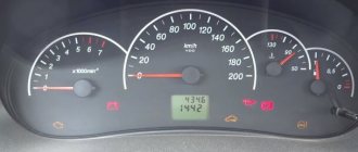
— How to adjust co and sn on my machine? VAZ 2114 2006 January 7.2 factory firmware, exhaust smells of gasoline.
— First, measure the CO and then draw conclusions.
— “CO” is regulated “automatically” by the ECU based on a signal from the DC. Check the condition of the DC and MAF.
— the state of the air flow sensor is voltage 1.02 with the ignition on (not started) and with the engine warm and idling, I disconnect the air flow sensor connector, the speed drops, approximately 550-600 rpm, I connect it back, it rises to 800-850 rpm. is this a normal DMRV? I haven’t checked the dk yet, because there is no pit and bk. The message has been edited by sardeaf: February 18, 2013 - 07:51
— The condition of the mass air flow sensor is checked using a scanner.
- Good day. Auto 21124, ECU January 7.2, firmware without DC. The problem is this. With an injection time correction factor of 1.000 and a CO correction factor of -0.004, the air/fuel ratio is 21. At the same time, the engine runs a little unevenly at idle, with slight tripping (about once every 3 seconds). When the CO correction coefficient changes by 0.25, the injection time correction coefficient is equal to 1.246 and the air/fuel ratio is equal to 11. At the same time, the engine runs much smoother, without any tripping, and the injection time and air mass flow are further reduced. The question is how to get the air/fuel ratio to 14.7? If none of the CO correction factor values are suitable.....
— since the system does not see the real situation, a gas analyzer can help.
— From the description it is clear that the mixture is lean. First, inspect the fuel system; wash the injectors, replace the seals on them, eliminate possible leaks in the intake, check the timing, check the intake manifold for leaks and replace the seals on it.
- All of the above has been done. All that remains is the “game” with the firmware. Is it possible that during the firmware the mixture was leaner (supposedly to save money), and now the “zero” of the CO correction coefficient is simply shifted? Post edited by Mix_64: March 15, 2021 - 07:30
— Install the factory software and check!
- Factory will not work. DC is missing. There is no point in installing a new DC. The car eats oil well. Therefore, I will try to sew non-serial ones without DC. The question remains the same, is it possible that during the firmware the mixture was leaner (supposedly to save money), and now the “zero” of the CO correction coefficient is simply shifted? If this is possible, then it makes sense to sew.
— It is quite possible to supply a working used recreation center. Many cars have them and are not used when installing non-factory software. + Another thing is that from the signal from the DC you can understand the state of the mixture: “poor” or “rich”. This question should be asked to the author of the firmware, because only he knows what he “set up” there!
— Accepted, then let's start with the firmware. It's easier than finding a working used recreation center))))
— maybe I’m missing the point, but from the description it’s only clear that this is the calculated composition of the mixture, and what’s actually going on is unknown. because we don’t know the true performance of the injectors, the condition of the air flow sensor, etc. and so on. or…? but otherwise I agree
Based on materials from the Lada Forum: lada-forum.ru
Additive mixture correction
Additive mixture correction operates at idle and partly in the lower load range. With additive mixture correction, fixed correction values are added to (or subtracted from) the calculated base injection time. Correction occurs when changes occur very quickly. The figure shows the operating principle of additive mixture correction.
Rice. Additive mixture correction
Example of additive mixture correction
Load and rpm - calculated ti + additive correction = tik Idle speed 850 min^-1 2 ms + e.g. 0.3 ms = 2.3 ms Part load 1150 min^-1 2.8 ms + e.g. 0.3 ms = 3.1 ms
Correction coefficient is low
#1 wisp
- Users
- 914 messages
- City: Kizlyar
- Gender: Man
#2 uncle_sem
- City: Brest, Belarus
- Gender: Man
Well, maybe lambda, for example, is messing around like that? or flow meter?
- maxkam, antikiller and Foxis like this
reading errors is not diagnostics, erasing errors is not repair (c) buying a tool does not make you a mechanic, buying a tester does not make you an electrician, buying a scanner does not make you a diagnostician (c)
#3 maxkam
- City: Solikamsk >> Penza
- Gender: Man
How much air consumption is it until the correction reaches 0.75?
Disconnect the connector from the mass air flow sensor, the ME1797 works fine without it.
Post edited by maxkam: 07 December 2021 — 11:15
- antikiller likes this
t. +79374477710 maxi-chip.car-services.ru
#4 avtonik
- City: Nizhnekamsk
- Gender: Man
Post has been edited by avtonik: 07 December 2021 — 11:15
- antikiller and SIG like it
#5 maxkam
- City: Solikamsk >> Penza
- Gender: Man
Then it’s not steam, but gasoline. DK sees a rich woman!
- nixe-1, antikiller and vasyan like this
t. +79374477710 maxi-chip.car-services.ru
#6 uncle_sem
- City: Brest, Belarus
- Gender: Man
Yes, by and large, at this stage it doesn’t matter whether he sees a rich woman or a poor woman. you need to find out which sensor signal has such a strong influence on the corrections and make sure it is working properly.
wrong mixture - what is it? flow meter, lambda, suction, fuel pressure (as an option - fuel leakage through the RTD vacuum) - these are due to natural reasons. if there is something to make sure that the same lambda probe is not lying, this simplifies the task. well, etc.
- Petrovich 86, CV joint and wisp like it
reading errors is not diagnostics, erasing errors is not repair (c) buying a tool does not make you a mechanic, buying a tester does not make you an electrician, buying a scanner does not make you a diagnostician (c)
#7 AmpeR73
Topol does not need a visa
- Krasnodar city
- Gender: Man
I haven’t seen it in the fields, of course. but on all sorts of priors, after installing the Stinger’s “Subaru sound”, the oxygen sensor begins to show the weather on Mars.
- Makkenek, antikiller, SIG and 1 other like this
#8 x1307
Vovan 8-920-653-88-09. Diagnostics and chiptuning in Rybinsk
- City: Rybinsk
- Gender: Man
#9 AmpeR73
Topol does not need a visa
- Krasnodar city
- Gender: Man
x1307 , just don’t laugh out loud)) personally, when I saw it live for the first time, I laughed for a long time. It imitates the sound of a Subaru engine, but in my subjective opinion it sounds like an incomprehensible fart.
cut, they put it on the field.
Multiplicative correction
Kmult is a dimensionless indicator. The limit of its changes lies in the range from 0.75 to 1.25. Exceeding the limit values of any self-learning coefficient indicates a significant deviation of the mixture composition from stoichiometry.
If Kmult becomes less than 0.78 or more than 1.22, the self-diagnosis system built into the unit will turn on the yellow check engine warning lamp. Likewise, the lamp will turn on if the long-term correction exceeds the 9 percent limit, i.e. reached a critical value, both in a positive and negative direction. By checking the DTC mask with a scanner, fault codes PO171 (poor mixture) or PO172 (rich mixture) are detected.
Short term trim (STFT) refers to immediate changes in fuel delivery that occur several times per second.
When diagnosing, you need to pay attention to the parameter line of the “DK1-Bank 1” scanner, where the operation of the oxygen sensor is monitored. When the sensor signal goes positive, the control unit instantly changes the short-term correction value towards minus, covering the nozzle spray. The meaning of the word “Bank 1” is found on almost all multi-brand scanners and means monitoring the fuel mixture in one cylinder block. On V-shaped engines, for example, the line “DK1-Bank 2” also works.
The reason for the deviation of the oxygen sensor readings towards the positive side may not be the tightness of the injectors, but towards the negative side (the signal drops into a lean mixture) - air leaks into the intake manifold.
Correction of air-fuel mixture adjustment
Modern injection systems are able to adjust the mixture composition within specified limits. The advantage of this correction is to compensate for changes due to engine wear as mileage increases and to always accurately adapt the mixture to the load range. Any changes that occur are detected by the lambda probe and the injection time is changed. The mixture is always adjusted to the ideal excess air ratio. If a mixture correction at a certain operating point is carried out repeatedly with the same quantity correction, then a long-term mixture correction is undertaken for this operating point and the correction value is written to the computer. No further adjustments to the mixture will be required at this operating point. The entire lambda control range from lean to rich mixture can again be used.
Answer: Injection duration of VAZ 2115
Auto VAZ 2115 2006 release. ECU Y7.2 AVTEL. firmware A203EL36
He arrives with a burning receipt and a complaint about the increased consumption, both according to the BC 1.2-1.4 l/h and according to calculations. He connects everything with the fact that he stood in the cold for a week (about -20), and that’s where it all started for him. At first it didn’t start, it was started only with a rope, and then it started to start without any help, either with a rope or replacing the spark plugs. I connect with the scanner and see error code 0172 (mixture too rich) and these are the parameters: Mass 11.5 kg/hour, duration 7.3 MS, cycle 144 mg/t, U.O.Z 8-10 degrees. The DC hangs at 780 Mv. and correction 0.699-0.703. After measuring the pressure in the ramp, checking the air inlet, playing with the IM, in particular with the CPA, the parameters themselves were restored. The duration of the cyclic 103 Mg/t is 3.95 MSc, the DC is running at 80-780 MW. the correction rose slightly to 0.803-0.865, the hourly flow rate was 1.2-1.3 l/h. But the DC sometimes froze at 800 MW for 15-20 seconds, and at that time the duration jumped to 7.3 Ms. The correction remained at the same level around 0 .65. I turn off the RTD and do not turn off the tube in the intake manifold, the following happens: Mass 8.5 kg/hour, duration 3.8 MS, cycle about 90 g/t, U.O.Z 8-10 degrees. The DC hangs at 650Mv. and the correction is 0.799-0.890 somewhere, the hourly fuel consumption is immediately 0.6-0.8. The fuel pressure is 3.5. I also tried this, lowered the fuel pressure to 2.5 and no change. only if you disconnect the tube from the RTD then everything more or less returns to normal. I washed the injectors, the same story, MAF -1.073 V. I think that DEATH is coming to the oxygen sensor. or not.
(1) Parameters
In practice, in most cases, fuel injection is carried out synchronously: one injection is performed per revolution of the engine crankshaft.
But during acceleration of the car, to increase engine power, asynchronous injection is performed along with synchronous injection. The time of synchronous injection is determined by formula (3.1): Duration of synchronous injection = main (base) injection time X correction factor + correction of injection time for changes in supply voltage. (3.1)
1) The main injection time is the time corresponding (as shown in section (2)) to the amount of fuel required to create the theoretically required excess air ratio (air-fuel ratio). In this case, the mass charge of air entering the cylinder per cycle is calculated based on data from the air flow sensor and engine crankshaft speed. These relations are represented by formula (3.2):
Main injection time = K (coefficient) X air flow / engine speed. (3.2)
2) Correction of injection time for changes in supply voltage
Since the response time of the electromagnetic injector varies depending on the supply voltage, adjustments must be made accordingly. The magnitude of the correction in the supply voltage function is presented in Fig. 3.4.
3) Correction of the amount of injected fuel
In order to improve the characteristics of the engine during its warm-up (stability of operation, throttle response, exhaust gas composition, etc.), various types of corrections are made to the amount of injected fuel relative to the main injection time. Below are examples of such corrections.
A. Correction for warm-up time
To improve the operation of a cold engine in winter, based on signals from the coolant temperature sensor, the amount of injected fuel is increased. After warming up is completed, the introduction of this correction stops. The change in correction is shown in Fig. 3.5.
b. Correction after engine start
Thanks to this correction, the engine speed is stabilized immediately after start-up. The dependence of the correction on the coolant temperature is provided in accordance with the graph shown in Fig. 3.6.
It stops after a certain time after starting.
V. Correction to increase engine response during warm-up
To increase engine response during warm-up, the correction coefficient depends on the coolant temperature, shown in Fig. 3.7.
d. Correction to prevent overheating
To avoid overheating of the engine, converter and other vehicle parts when driving at maximum power, it is necessary to enrich the fuel mixture. To do this, a special correction of the injection time is introduced depending on the signals from the air flow sensors, crankshaft speed, etc.
d. Correction based on intake air temperature
Since the density of air changes with its temperature, the correction shown in Fig. 3.8.
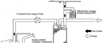
e. Air-fuel ratio correction using feedback method
In Fig. Figure 3.9 shows the dependence of the emission of exhaust gas components on the excess air coefficient (lambda), which characterizes the composition of the combustible mixture.
In order to simultaneously achieve a high degree of exhaust gas purification in terms of CO, HC and NOx components using a three-component neutralizer, it is necessary under different engine operating conditions to precisely adjust the excess air ratio so that the mixture composition is as close as possible to stoichiometric. For this purpose, a sensor installed in the exhaust system measures the oxygen concentration in the exhaust gases. In this way, feedback is organized in the system for automatically stabilizing the stoichiometric composition of the combustible mixture.
In Fig. Figure 3.10 shows a diagram of the air-fuel ratio control system with feedback from the oxygen sensor and the shape of the output signal of the oxygen sensor.
However, the oxygen sensor does not work while its temperature is low. Therefore, before the end of warm-up, the actual air-fuel ratio is determined by the ECU without using an oxygen sensor.
Answer: Injection duration of VAZ 2115
The air flow sensor is absolutely fine. With a cyclic flow rate of 112 mg, the calculated intake pressure is 25 kPa for a one and a half liter engine. This is absolutely working pressure at xx. This immediately leads to another conclusion - there are no leaks at the inlet. If anyone doubts it, pick up a calculator and go ahead. Fuel pressure is also normal. Plus or minus a couple of tenths is not critical. The over-enrichment in fuel is apparently due to incorrect operation of the lambda. If you are confident in its serviceability, then it is possible that the exhaust system in front of it is leaking (cracks in the manifold, gasket). She sees excess oxygen and pours fuel. Start by turning off the DC. If the injection time returns to normal, then work in this direction. There were cars with cracked manifolds and increased consumption by one to two times.