First option
Early cars were equipped with a mechanical speedometer driven by a flexible shaft of the GV 310 model. The flexible shaft was installed at one end on the gearbox housing, and the other was attached to the speedometer housing. The drive was carried out from a helical gear mounted on the secondary shaft in the gearbox. It is located closer to the rear shaft bearing.
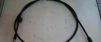
The speed sensor of the Gazelle in this case was the speed measuring device itself. The flexible shaft rotated the magnetic disk, creating a magnetic field. Its intensity depended on the shaft rotation speed. This field turned the spring-loaded needle. The Gazelle speedometer drive cable is shown in the photo.
Drive maintenance consisted of timely lubrication of rotating components and control over the route of the cable. The radii of cable bends should not be more than 150 mm.
How to check the speedometer on a gazelle. Where to begin?
After some time, the car owner may discover that the speedometer on the gazelle does not work. This means an inevitable inspection, starting with the sheath cable. It is with this part of the car that problems arise more often than with others. The first thing to inspect is the union nuts (fastening the gearbox and the cable sheath built into the mechanical speedometer), since due to constant vibration vibrations they could become unscrewed. Shifted nuts can be seen by frequent jumping of the cable, as a result of which torque will not be supplied. The cable break can then be checked directly in the sheath. A phenomenon such as cycling may well cause the speedometer to fail.
After the reasons have been found and eliminated, it is necessary to adjust the mileage; if with a mechanical speedometer this can be done independently, then in the case of an electronic mechanism you should contact specialists who will correctly adjust the mileage without causing harm to the car and all electronics.
The malfunction in most cases consists of wide fluctuations (strong deviations) of the speed indicator needle, which becomes a reason for the owner/driver of the gazelle to doubt the speed readings of the device. The cause of the problem may well be missing lubrication on the shell (internal). It is because of this that the cable rotates incorrectly (unevenly), as a result of which it begins to slow down. The situation is similar with the loosened nuts with which the shell is attached to the gazelle. It doesn’t matter what the reason was for removing and reinstalling the cable, if the owner performed this procedure, exceeding the permissible bend (radius more than 15 cm), the rotation of the cable will become difficult, and the indicator arrow will begin to fluctuate, preventing an accurate determination of the speed of the vehicle.
Restyled version
Since 2003, cars began to be equipped with a new instrument cluster with an electronic speedometer. The new Gazelle speed sensor was designated DS-6 and was installed on the gearbox housing on the left side. The sensor had a mechanical drive similar to a cable. The same device was used at Gazelle Business.
The operation of the sensor is based on the Hall effect principle. Any change in speed is recorded by a sensor and transmitted in the form of voltage pulses to the controller of the electronic control unit. They have a lower limit of about 1 Volt and an upper limit of at least 5 Volts.
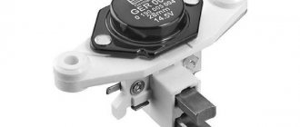
There is a proportional relationship between the speed and pulse frequency, so the sensor error is small. As the speed increases, the pulse frequency also increases, but the sensor has a design limitation - the pulse counter readings cannot be higher than 6004 per kilometer. The controller calculates the speed based on the number of pulses and the time intervals between them. The received signal is transmitted to the speedometer located on the dashboard of the car. The photo shows the electronic sensor of the Gazelle.
The design of the sensor is quite simple and, in general, it does not cause problems for car owners. Replacing the Gazelle Business speed sensor is quite simple. Before starting work, it is advisable to disconnect the battery from the vehicle's on-board network. To remove the sensor, it is necessary to remove the hatch located next to the gear shift lever. The sensor can also be accessed from below. To loosen the fastening nut, a wrench with a jaw size of 22 mm is required. After loosening the nut, the sensor can be easily unscrewed by hand and removed from the drive. On the other hand, it is equipped with a regular connector with plastic latches.
Sometimes there is an oil leak through the sensor drive, which oils the contacts and disrupts operation. The drive itself is fixed with a clamping bracket, to remove which you need to unscrew one 10 mm bolt. After this, the drive can be removed from the box housing to replace the ring rubber gasket.
Purpose of elements on the GAZ instrument panel
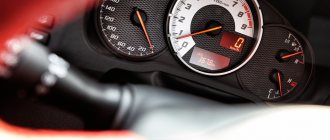
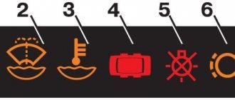
1 — the voltmeter indicates the voltage in the on-board network of the GAZ car; 2 — warning lamp of the engine management system; 3 - reserve (or abs malfunction warning lamp on a Volga GAZ car equipped with an anti-lock brake system); 4 — “STOP” light display. Lights up simultaneously with one of the malfunction indicator lamps, if further movement with this malfunction is prohibited; 5 - indicator lamp for turning on the left turn signal. The lamp lights up simultaneously with the left turn indicators. If one of the indicator lamps malfunctions, the control lamp blinks at double frequency; 6 - warning lamp for emergency drop in brake fluid level. The lamp lights up when the fluid level drops (below the minimum allowable) in the brake master cylinder reservoir. As the brake pad linings wear, it is necessary to add brake fluid; 7 — odometer (total mileage counter); 8 — the speedometer indicates the speed of the car; 9 - indicator lamp for turning on the parking brake. The lamp lights up when the parking brake lever is raised and the ignition is on. 10 — control lamp for turning on the right turn signal. The lamp lights up simultaneously with the right turn indicators. If one of the indicator lamps malfunctions, the control lamp blinks at double frequency; 11 - reserve; 12— warning lamp for unfastened seat belts (installed on some Volga GAZ 31105 cars); 13 or 18 - warning lamp for emergency drop in oil pressure in the engine lubrication system. The lamp should light up when the ignition is turned on and go out after starting the engine. If the light remains on after the engine has started, or comes on while the engine is running, stop the engine immediately and check the oil level. The level is normal - the engine is faulty. For a car with high mileage, the lamp may come on when the warm engine is idling; 14 — reserve (for installing additional warning lamps); 15 — fuel level indicator. The device shows the approximate amount of fuel in the tank. The scale has divisions: 0 - empty tank; 1/2 - half a tank; 1 - full tank: 16 - fuel reserve warning lamp. The lamp turns on when the remaining fuel in the tank is less than 8 liters; 17 — oil pressure indicator in the engine lubrication system allows you to assess the technical condition of the engine; 19 — control lamp for turning on heated seats (for GAZ 31105 vehicles with heated seats); 20 — coolant temperature gauge allows you to control the engine temperature; 21 — control lamp for turning on external lighting (side light); 22 - the coolant overheating warning lamp turns on when the coolant temperature rises above the permissible value; 23 - control lamp for turning on the high beam headlights. The lamp turns on when the high beam headlights are turned on; 24 — button for setting the daily mileage counter to zero. In order to reset the counter readings, you must press the button; 25 — car daily mileage counter. To reset the counter readings, you must press the zero setting button (pos. 24); 26 - tachometer. The device shows the engine speed; 27 - battery discharge warning lamp. The lamp should light up when the ignition is on, and go out after starting the engine. Illumination of the lamp while the engine is running may indicate a malfunction of the generator or its circuits.
Speed sensor connection diagram
In the graphical representation of the automotive system, you can see that three wires extend from the desired analyzer. In most cases this is the case, except for some brands of cars that use four-wire analyzers.
Let's return to the three-wire option:
The speed sensor connection diagram may, at first glance, seem complex and confusing. But, if you make a little effort and study it along with the instructions, then understanding this interweaving of wires and connections will not be difficult. And the resulting knowledge can greatly facilitate future repairs and maintenance of your car.
Niva Chevrolet car speed sensor
The device used in this machine is an electronic type that works according to the Hall effect. It transmits a signal to the control unit every time the car travels one kilometer (this is approximately 6004 pulses). The faster the car goes, the more often the sensor transmits a signal.
The circuit of this type of speed sensor consists of a coil, a core and a semiconductor, which create a magnetic field during operation of the device. There are three wires coming from the analyzer, which were already mentioned above, so there is no point in repeating them.
READ The shower mixer does not work, how to connect it
The Niva's DS is located at the gearbox, as in many other cars, in direct contact with the shaft.
Causes of detector malfunction:
Speed sensor Niva Chevrolet
| № | Helpful information |
| 1 | malfunctions in the speedometer, up to the complete impossibility of turning it on |
| 2 | indicator signal on the dashboard |
| 3 | on-board computer error code |
| 4 | excess fuel consumption |
| 5 | difficulty starting the engine |
| 6 | weak motor power |
Replacing the analyzer involves a standard set of actions - disconnect the battery, remove the block of wires from the sensor, dismantle the sensor itself (in the Niva Chevrolet it is unscrewed with a key), after which the broken part is replaced with a new one and the system is reassembled.
Source
Speed sensor malfunction
A malfunction of the speed sensor usually leads to incorrect operation of the speedometer (the needle jumps), but other troubles can also occur depending on the car. In particular, failures in gear shifting may occur if the transmission is automatic and not manual, the odometer does not work, and the ABS system or engine traction control system (if any) will be forcibly disabled. In addition, on injection cars, errors with codes p0500 and p0503 often occur along the way.
If the speed sensor fails, it is hardly possible to repair it, so it is simply replaced with a new one. However, what to do in such a situation is still worth finding out after several checks.
First option
Early cars were equipped with a mechanical speedometer driven by a flexible shaft of the GV 310 model. The flexible shaft was installed at one end on the gearbox housing, and the other was attached to the speedometer housing. The drive was carried out from a helical gear mounted on the secondary shaft in the gearbox. It is located closer to the rear shaft bearing.
The speed sensor of the Gazelle in this case was the speed measuring device itself. The flexible shaft rotated the magnetic disk, creating a magnetic field. Its intensity depended on the shaft rotation speed. This field turned the spring-loaded needle. The Gazelle speedometer drive cable is shown in the photo.
Drive maintenance consisted of timely lubrication of rotating components and control over the route of the cable. The radii of cable bends should not be more than 150 mm.
Restyled version
Since 2003, cars began to be equipped with a new instrument cluster with an electronic speedometer. The new Gazelle speed sensor was designated DS-6 and was installed on the gearbox housing on the left side. The sensor had a mechanical drive similar to a cable. The same device was used at Gazelle Business.
The operation of the sensor is based on the Hall effect principle. Any change in speed is recorded by a sensor and transmitted in the form of voltage pulses to the controller of the electronic control unit. They have a lower limit of about 1 Volt and an upper limit of at least 5 Volts.
There is a proportional relationship between the speed and pulse frequency, so the sensor error is small. As the speed increases, the pulse frequency also increases, but the sensor has a design limitation - the pulse counter readings cannot be higher than 6004 per kilometer. The controller calculates the speed based on the number of pulses and the time intervals between them. The received signal is transmitted to the speedometer located on the dashboard of the car. The photo shows the electronic sensor of the Gazelle.
The design of the sensor is quite simple and, in general, it does not cause problems for car owners. Replacing the Gazelle Business speed sensor is quite simple. Before starting work, it is advisable to disconnect the battery from the vehicle's on-board network. To remove the sensor, it is necessary to remove the hatch located next to the gear shift lever. The sensor can also be accessed from below. To loosen the fastening nut, a wrench with a jaw size of 22 mm is required. After loosening the nut, the sensor can be easily unscrewed by hand and removed from the drive. On the other hand, it is equipped with a regular connector with plastic latches.
Sometimes there is an oil leak through the sensor drive, which oils the contacts and disrupts operation. The drive itself is fixed with a clamping bracket, to remove which you need to unscrew one 10 mm bolt. After this, the drive can be removed from the box housing to replace the ring rubber gasket.
Third option
The Gazelle Next speed sensor is somewhat different from previous models. It is electromagnetic and has four wires going to the controller. Previous sensors only had three wires. A new type of device is shown in the photo.
The sensor has part number A63R42.3843010-01, is equipped with a 22 mm nut on the housing and is screwed into the gearbox housing.
Gazelle speed sensor does not work
The vehicle speed sensor (VS) is designed on the principle of the Hall effect and outputs a frequency-pulse signal to the controller.
The frequency of the signal is directly proportional to the speed of the vehicle. The controller uses this signal to control engine idle speed and, through the idle speed control, controls the air supply bypassing the throttle valve. The DSA produces approximately 6004 pulses for every kilometer traveled by the vehicle. Based on the time interval between pulses, the controller determines the speed of the vehicle. In addition, this signal can be used by the speedometer installed on the instrument panel. The appearance of vehicle
speed sensor To get to the speed sensor on the Gazelle, you need to unscrew all the screws securing the hatch around the gear shift knob:
We pull out and disconnect the sensor chip. Checking the functionality of the DSA should begin with the presence of grounding on pin “3” and supply voltage (+12V) on pin “1”. The black wire is negative and the yellow wire is positive, the green wire goes to the controller and to the instrument panel, as can be seen from the diagram:
Where number 66 is our speed sensor. We also see that the positive going to our sensor comes to the reverse switch, so if the reverse lights light up when you turn on reverse gear and the ignition, then you don’t have to check the fuse.
READ How to connect your home internet beeline on your computer
But here is the electrical circuit, after assembling it, you can check the speed sensor itself:
Or connect another (known good) sensor to the connector, turn on the ignition and turn the sensor shaft and look at the speedometer needle, it twitches - that means everything is fine, the sensor should be replaced.
In my case there was no negative on the black wire. I cleaned it up and wound up additional mass:
I soldered the twist and insulated it well:
I passed the wire under the rubber mat and screwed it between the seats to ground:
CONNECTING THE WINDING ON UAZ, VAZ.
To connect to a speed sensor
A winder with a chip is better suited, to do this, turn on the ignition, connect the winder to the
speed sensor
, the green LED should light up, use a screwdriver to set the desired speed.
Do not connect it to foreign cars, the chip is similar, but the pinout of the wires is different, the winding will burn out immediately!
CONNECTING THE WINDING TO GAZELLE BUSINESS, GAZELLE.
Speed sensor chip
The gazelle is round, the mating part is expensive to find, so the connection is wired. On the winding, the wires are labeled on cambrics.
Here is the pinout of the chip for the gazelle speed sensor.
We insert the winding wires, turn on the ignition, the green LED will light up, use a screwdriver to set the desired speed.
INSERTING THE WINDING INTO THE WIRING.
Many people are not happy that they have to constantly crawl under the car, here are instructions on how to connect the winder behind the instrument panel (on the Patriot, the Patriot with the new panel and on the Gazelle, the connection is the same, the chip is behind the XP3 panel). To connect, first prepare the winding, you will need wires, a soldering iron, electrical tape, tools and find a toggle switch for six pins with two switching positions, these are great:
Next, solder the wires according to this diagram:
Afterwards we remove the instrument panel, the XP3 chip, in the photo there are wires to which you need to connect.
There is a double signal wire, we cut both. After everything is connected, we check and set the desired speed, we hide the toggle switch where we find it convenient.
Now, when driving in the first position of the toggle switch, everything works normally, in the second position the speedometer will work by winding, and you can drive the car.
Points for inserting into the speedometer of the UAZ Hunter, “bun” with the AP speedometer.
Firmware VAZ M17.9.7
Firmware for VAZ “classic”
Lenovo S750 Firmware, ROOT, installing TWRP, BackUp firmware
Description
: Lenovo S750 Firmware, ROOT, installing TWRP, BackUp firmware
GAZ Gazelle business 4x4 Titan - pinout
1 - not connected 2 - 382.3801 has an open door alarm (may not be present). You can run a wire to the limit switch on the driver's door. 3 - 382.3801 has an oil overheating indicator (may not be present). You can run a wire to the TM-108 overheating sensor, and put the sensor itself into the crankcase. 4 - 385.3801 has an open door alarm (may not have one). You can run a wire to the limit switch on the driver's door. 5 - 382.3801 has a test. If ground is applied to this contact, the indicators for brake fluid level, oil overheating, open doors and coolant overheating light up. Can be connected to a button or relay. In the second case, the relay winding is connected to ground and the wire from the lock to the starter (i.e., when the starter is turned on, the lamps will be tested). 6 - 382.3801 has a seat belt warning indicator (may not be present). 7 - 382.3801 has a fuel reserve indicator. Connect the blue wire with the red stripe. 8 — fuel level indicator. Connect to the pink wire with the red stripe. 9 — oil pressure indicator. At 382.3801, run a wire to the sensor (you need a VAZ-2106 tee) from GAZ under the ZMZ-406 engine. With 385.3801, if you install a sensor, it will squeak about low pressure at idle, so a sensor is not needed, you need to connect the wire from the device to ground through a resistor, select it experimentally. 10 — emergency oil pressure indicator. Connect to the gray wire with a blue stripe. 11 — engine overheat indicator. Can be connected to overheat sensor TM-111-02. The sensor itself must be in contact with the coolant. 12 — coolant temperature indicator. Connect to the green wire with a white stripe. The pointer will exaggerate the readings; you can connect a resistor to the wire gap and select it experimentally. 13 - indicator for closing the carburetor air damper. Connect to the gray wire with an orange stripe if the car is a carb. 14 - for 382.3801 the indicator may be on and will light up when the mass is supplied. 15 - downshift indicator (may not be present), will light up when the mass is supplied. 16 - differential lock indicator (may not be present), will light up when the mass is supplied. 17 - for 382.3801, the seat heating indicator will light up when positive is applied. 18 - rear PTF indicator (may not be present), lights up when positive is applied. 19 — side light indicator. Connect to the yellow wire. 20 — instrument lighting lamps. Connect to the white wire. 21 - 385.3801 has power supply to the meter. Connect to constant power (red-white wire of stop switch). 22 and 23 - right and left turn signal indicators, respectively. You can connect them together and connect to a blue wire with a white stripe (the arrows will light up when the left or right turn signal is turned on), or to the hazard warning switch: blue - right, blue-black - left, insulate the blue wire with a white stripe (each arrow will correspond to the activation of its turn signal). 24 - parking brake indicator. Connect to the brown wire. 25 - high beam headlight indicator. Connect to the green wire with a black stripe. 26 - front PTF indicator (may not be present), lights up when positive is applied. 27 - ABS indicator. When the mass is supplied it will light up. 28 - 385.3801 has a rear window heating indicator. Lights up when positive is applied. 29 — speed signal output to the on-board computer. If it is, then take the speed signal from this contact. 30 - to the vehicle speed sensor. 31 - low brake fluid level indicator. Connect to the pink wire with a blue stripe that goes to the lamp above the cigarette lighter. 32 - power supply for lamps and devices. Connect to the orange wire with the blue stripe. 33 - battery charge indicator. Connect to the brown wire with a white stripe. 34 - mass. Connect to the black wire. Wow, I wrote a lot... 35 — speedometer power supply. Connect to the orange wire. 36 — speedometer mass. Connect to the white wire with a black stripe. 37 - tachometer. Connect to the brown wire with a blue stripe, but if the readings drop, connect to pin 38. 39 - 385.3801 has a low beam indicator (it may not be present), it will light up when positive is applied. 40 - low oil level indicator (may not be present), will light up when the mass is supplied. 41 - if the car is injection, connect to the orange wire too. 42 - if the car is injection, connect to the remaining wire (I don’t know the color) it went to the 8-terminal block on the old device. 43 - brake pad wear indicator (may not be present), will light up when the mass is supplied. 44 - glow plug indicator. 45 and 46 - does not connect. 47 - low coolant level indicator (may not be present), will light up when the mass is supplied. 48 - low washer fluid level indicator (may not be present), will light up when mass is supplied. 49 - low power steering oil level indicator (may not be present), will light up when the mass is supplied. 50 - the indicator for burnt out lamps on 382.3801 or the presence of water in the fuel filter on 385.3801 (may not be present) will light up when the mass is supplied. 51 and 52 - 382.3801 has indicators (may not be present) that will light up when the mass is supplied.
GAZ 2705 | Checking the condition and replacing the speed sensor
Checking the condition and replacing the vehicle speed sensor (VSS)
The VSS is mounted on the transmission housing and is a variable reluctance sensor that begins to produce voltage pulses as soon as the vehicle speed exceeds 4.8 km/h (3 mph). Pulses from the sensor are sent to the PCM and are used by the module to control the duration of the opening time of the fuel injection injectors and the transmission shift. On models with manual transmission, one VSS is used, on models equipped with AT, there are two speed sensors: one is connected to the secondary shaft of the gearbox, the second is connected to the intermediate shaft, and the failure of any of them leads to problems with transmission shifting.
1. Disconnect the sensor wiring harness connector. Using a voltmeter, measure the voltage at the connector (harness side). The positive probe of the voltmeter should be connected to the terminal of the black and yellow wire, the negative one to ground. The connector must have battery voltage present. If there is no power, check the condition of the VSS wiring between the sensor and the fuse mounting block (on the left under the instrument panel). Also make sure that the fuse itself is working properly. Using an ohmmeter, check for continuity between the black connector wire terminal and ground. If there is no continuity, check the condition of the black wire and the quality of its terminal connections. 2. Jack up the front of the car and place it on jack stands. Support the rear wheels with wheel chocks and shift the transmission to neutral. Connect the electrical wiring to the VSS, turn on the ignition (do not start the engine) and test the signal (blue-white) wire terminal on the back of the connector with a voltmeter (connect the negative probe to body ground). While holding one of the front wheels stationary, manually turn the opposite one - the voltage should range from zero to 5 V, otherwise replace the VSS.
3. Disconnect the wiring from the appropriate speed sensor. Using an ohmmeter, measure the resistance between the two sensor terminals. The nominal value is approximately 400 ÷ 600 Ohm, otherwise replace the sensor.
1. Disconnect the electrical wiring from the speed sensor. 2. Unscrew the mounting screw and remove the sensor from the transmission housing. 3. Installation is carried out in reverse order. Don't forget to replace the O-ring.
Gazelle Speed Sensor
Gazelle speed sensor does not work
The vehicle speed sensor (VS) is designed on the principle of the Hall effect and outputs a frequency-pulse signal to the controller. The frequency of the signal is directly proportional to the speed of the vehicle. The controller uses this signal to control engine idle speed and, through the idle speed control, controls the air supply bypassing the throttle valve. The DSA produces approximately 6004 pulses for every kilometer traveled by the vehicle. Based on the time interval between pulses, the controller determines the speed of the vehicle. In addition, this signal can be used by the speedometer installed on the instrument panel. The appearance of the vehicle speed sensor is shown in Photo-1.
READ How to connect an Apollo shower cabin
To get to the speed sensor on the Gazelle, you need to unscrew all the screws securing the hatch around the gear shift knob:
We pull out and disconnect the sensor chip. Checking the functionality of the DSA should begin with the presence of grounding on pin “3” and supply voltage (+12V) on pin “1”. The black wire is negative and the yellow wire is positive, the green wire goes to the controller and to the instrument panel, as can be seen from the diagram:
Where number 66 is our speed sensor. We also see that the positive going to our sensor comes to the reverse switch, so if the reverse lights light up when you turn on reverse gear and the ignition, then you don’t have to check the fuse.
But here is the electrical circuit, after assembling it, you can check the speed sensor itself:
Or connect another (known good) sensor to the connector, turn on the ignition and turn the sensor shaft and look at the speedometer needle, it twitches - that means everything is fine, the sensor should be replaced.
In my case there was no negative on the black wire. I cleaned it up and wound up additional mass:
I soldered the twist and insulated it well:
I passed the wire under the rubber mat and screwed it between the seats to ground:
CONNECTING THE WINDING ON UAZ, VAZ.
To connect a speed sensor to a chip, a winder with a chip is better suited; to do this, turn on the ignition, connect the winder to the speed sensor chip, the green LED should light up, and use a screwdriver to set the desired speed.
Do not connect it to foreign cars, the chip is similar, but the pinout of the wires is different, the winding will burn out immediately!
CONNECTING THE WINDING TO GAZELLE BUSINESS, GAZELLE.
The gazelle speed sensor chip is round, the counter part is expensive to find, so the connection is wired. On the winding, the wires are labeled on cambrics.
Here is the pinout of the chip for the gazelle speed sensor.
We insert the winding wires, turn on the ignition, the green LED will light up, use a screwdriver to set the desired speed.
INSERTING THE WINDING INTO THE WIRING.
Many people are not happy that they have to constantly crawl under the car, here are instructions on how to connect the winder behind the instrument panel (on the Patriot, the Patriot with the new panel and on the Gazelle, the connection is the same, the chip is behind the XP3 panel). To connect, first prepare the winding, you will need wires, a soldering iron, electrical tape, tools and find a toggle switch for six pins with two switching positions, these are great:
Next, solder the wires according to this diagram:
Afterwards we remove the instrument panel, the XP3 chip, in the photo there are wires to which you need to connect.
There is a double signal wire, we cut both. After everything is connected, we check and set the desired speed, we hide the toggle switch where we find it convenient.
Now, when driving in the first position of the toggle switch, everything works normally, in the second position the speedometer will work by winding, and you can drive the car.
Points for inserting into the speedometer of the UAZ Hunter, “bun” with the AP speedometer.
Firmware VAZ M17.9.7
Firmware for VAZ “classic”
Lenovo S750 Firmware, ROOT, installing TWRP, BackUp firmware
I bought it here https://goo.gl/u2W98QAliexpress.com https://goo.gl/yRMLLPVK Group https://vk.com/garant_500
All you need for the firmware is https://4pda.ru/forum/index.php?showto.
Firmware version 1.1 – https://4pda.ru/forum/index.php?showto.
TWPR CWM – https://disk.yandex.ua/public/?hash=r.
How to check a speed sensor with a multimeter - Auto workshop online
If the engine stalls while idling , then most likely you will need to check several sensors (mass air flow sensor, air sensing sensor, speed control valve, air pressure sensor) in order to determine the culprit. Previously we looked at verification methods:
Now, checking the speed sensor yourself will be added to this list.
If this sensor malfunctions, it transmits erroneous data, which leads to disruption of not only the engine, but also other components of the car. The vehicle speed meter (VSM) sends signals to the sensor, which controls the operation of the engine at idle speed , and also, using PPX, controls the air flow bypassing the throttle valve. The higher the speed of the car, the higher the frequency of these signals.
Operating principle of the speed sensor
The speed sensor design of most modern cars is based on the Hall effect. During its operation, it transmits pulse-frequency signals to the vehicle's ECU at short intervals.
In particular, over one kilometer of travel, the sensor transmits about 6,000 signals. In this case, the frequency of impulse transmission is directly proportional to the speed of movement.
Based on the frequency of signals received, the electronic control unit automatically calculates the speed of the machine. It contains a program for this purpose.
The Hall effect is a physical phenomenon that involves the generation of electrical voltage when a conductor carrying direct current is placed in a magnetic field.
The speed sensor itself is located next to the gearbox, in particular, in the speedometer drive mechanism. The exact location differs between different car brands.
How to determine that the speed sensor is not working
You should immediately pay attention to such signs of malfunction as:
- no idle stability;
- the speedometer does not function correctly or does not function at all;
- increased fuel consumption;
- reduced engine thrust.
Also, the on-board computer may display an error about the absence of signals on the DSA. Naturally, if BC is installed on the machine.
Speed sensor
Speed sensor location
Most often, the malfunction is caused by a broken circuit, so first of all, you need to diagnose its integrity. First you need to disconnect the power and inspect the contacts for oxidation and dirt. If it is, then you need to clean the contacts and apply Litol.
often break near the plug , because this is where they bend and the insulation can fray. You also need to check the resistance in the grounding circuit, which should be 1 ohm. If the problem has not been resolved, then it is worth checking the speed sensor for functionality. Now the question arises: how to check the speed sensor?
On VAZ cars, and on others too, a sensor is often installed that operates according to the Hall effect (as a rule, it produces 6 pulses per full revolution). But there are also sensors of a different principle: reed and inductive . First, let's look at testing the most popular DSA - based on the Hall effect. The sensor is equipped with three contacts: ground, voltage and pulse signal.
Checking the speed sensor
First you need to find out whether there is grounding and 12 V voltage in the contacts. These contacts are wired, and the contact with pulse signals is tested by torsion.
The voltage between the pin and ground should be in the range from 0.5 V to 10 V.
- We remove the speed sensor.
- We use a voltmeter. Let's find out which terminal is responsible for what. We connect the incoming contact of the voltmeter to the terminal that outputs pulse signals. We ground the second contact of the voltmeter to the engine or machine body.
- By rotating the speed sensor, we determine whether there are signals in the operating cycle and measure the output voltage of the sensor. To do this, you can put a piece of tube on the sensor axis (twist at a speed of 3-5 km/h). The faster you rotate the sensor, the higher the voltage and frequency in the voltmeter should be.
- Place the car on a jack so that one wheel does not touch the ground.
- We connect the contacts of the sensor with a voltmeter.
- We rotate the wheel and diagnose whether voltage appears - if there is voltage and frequency in Hz, then the speed sensor is working.
- Disconnect the pulse wire from the sensor.
- Using the control, we look for “+” and “–” (after turning on the ignition ).
- We hang one wheel as in the previous method.
- We connect the control wire to the “Signal” wire and rotate the wheel with our hands. If “-” lights up on the control panel, then the speed sensor is working.
If you don’t have a control at hand, you can use a wire with a light bulb. The test is carried out as follows: connect one side of the wire to the battery positive. Another signal to the connector. When rotating, if the sensor is working, the light will blink.
Connection diagram
Checking the DS with a tester
- We jack up the car to hang up any front wheel.
- We look with our fingers for the sensor drive that sticks out of the box.
- We rotate the wheel with our foot.
Speed sensor drive
Checking the DS drive
We feel with our fingers whether the drive is working and whether it is working stably. If everything is wrong, then we disassemble the drive and usually find damaged teeth on the gears.
Checking the DS with a reed switch
The sensor produces signals in the form of rectangular pulses. The cycle is 40-60%, and switching occurs from 0 to 5 volts or from 0 to battery voltage.
Checking the induction DS
The signal that comes from the rotation of the wheels essentially resembles the oscillation of a wave impulse. Therefore, the voltage changes depending on the rotation speed. Everything happens in the same way as with the crankshaft angle sensor.
to our channel in Yandex.Zen
Even more useful tips in a convenient format
Subscribe
Did not find an answer to your question?
Source: https://autogearspb.ru/uhod-za-avtomobilem/kak-proverit-datchik-skorosti-multimetrom.html

