First option
Early cars were equipped with a mechanical speedometer driven by a flexible shaft of the GV 310 model. The flexible shaft was installed at one end on the gearbox housing, and the other was attached to the speedometer housing. The drive was carried out from a helical gear mounted on the secondary shaft in the gearbox. It is located closer to the rear shaft bearing.
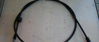
The speed sensor of the Gazelle in this case was the speed measuring device itself. The flexible shaft rotated the magnetic disk, creating a magnetic field. Its intensity depended on the shaft rotation speed. This field turned the spring-loaded needle. The Gazelle speedometer drive cable is shown in the photo.
Drive maintenance consisted of timely lubrication of rotating components and control over the route of the cable. The radii of cable bends should not be more than 150 mm.
How to wind up the speedometer
GAZelle cars were equipped with speedometers of several designs:
- with mechanical drive of all elements;
- with electronic drive speed indicator and mechanical odometer;
- electronic version with LCD screen.
Depending on the type of construction, different mileage adjustment techniques are used. If the owner is not confident in his abilities and knowledge, it is recommended to contact workshops that provide such a service.
On early GAZelle cars equipped with a mechanical speed meter, adjustment is carried out by rotating the cable from the electric motor. You can wind up a GAZelle Business with early versions of electromechanical meters using a motor from a computer fan. Power is supplied from the cigarette lighter socket, a free wire with green or yellow insulation is connected to the block (to the green conductor) located above the brake pedal. After turning on the ignition, winding begins.
Restyled version
Since 2003, cars began to be equipped with a new instrument cluster with an electronic speedometer. The new Gazelle speed sensor was designated DS-6 and was installed on the gearbox housing on the left side. The sensor had a mechanical drive similar to a cable. The same device was used at Gazelle Business.
The operation of the sensor is based on the Hall effect principle. Any change in speed is recorded by a sensor and transmitted in the form of voltage pulses to the controller of the electronic control unit. They have a lower limit of about 1 Volt and an upper limit of at least 5 Volts.
There is a proportional relationship between the speed and pulse frequency, so the sensor error is small. As the speed increases, the pulse frequency also increases, but the sensor has a design limitation - the pulse counter readings cannot be higher than 6004 per kilometer. The controller calculates the speed based on the number of pulses and the time intervals between them. The received signal is transmitted to the speedometer located on the dashboard of the car. The photo shows the electronic sensor of the Gazelle.
The design of the sensor is quite simple and, in general, it does not cause problems for car owners. Replacing the Gazelle Business speed sensor is quite simple. Before starting work, it is advisable to disconnect the battery from the vehicle's on-board network. To remove the sensor, it is necessary to remove the hatch located next to the gear shift lever. The sensor can also be accessed from below. To loosen the fastening nut, a wrench with a jaw size of 22 mm is required. After loosening the nut, the sensor can be easily unscrewed by hand and removed from the drive. On the other hand, it is equipped with a regular connector with plastic latches.
Sometimes there is an oil leak through the sensor drive, which oils the contacts and disrupts operation. The drive itself is fixed with a clamping bracket, to remove which you need to unscrew one 10 mm bolt. After this, the drive can be removed from the box housing to replace the ring rubber gasket.
Gazelle instrument panel, pinout and panel diagram
Instrument cluster 3110.3801000-90 for GAZ vehicles. Pinout.
Description of the combination of instruments and signaling devices.
Location of contacts in the gearbox connectors.
Connection of external signals to the control panel must be carried out using 13-pin socket connectors in accordance with OST 37.003.032-88.
Purpose of signals in the CP connectors.
| Contact | Signal name |
| 1 | Coolant temperature sensor |
| 2 | Emergency high coolant temperature |
| 3 | Emergency low oil pressure in the engine |
| 4 | Oil pressure sensor |
| 5 | Fuel level sensor |
| 6 | Free contact |
| 7 | Free contact |
| 8 | Open bus doors |
| 9 | Free contact |
| 10 | Open interior doors, hood or trunk |
| 11 | Free contact |
| 12 | Free contact |
| 13 | Malfunction of the Electronic Brake Force Control (EBD) |
| Contact | Signal name |
| 1 | Battery |
| 2 | Turning on the starboard turn signal lamps |
| 3 | Turning on the left side turn signal lamps |
| 4 | Engaging the parking brake |
| 5 | Turning on the high beam headlights |
| 6 | Turning on the front fog lights |
| 7 | Instrument cluster illumination |
| 8 | Turning on the side lights |
| 9 | Turning on the rear fog lights |
| 10 | Free contact |
| 11 | Enabling the center differential lock |
| 12 | Downshifting |
| 13 | Oil pressure sensor type |
| Contact | Signal name |
| 1 | Housing (for analog signals) |
| 2 | Ignition |
| 3 | Frame |
| 4 | High voltage tachometer input |
| 5 | Low voltage tachometer input |
| 6 | Turning on the low beam headlights |
| 7 | Low battery |
| 8 | Ignition |
| 9 | Low brake fluid level |
| 10 | Speed sensor |
| 11 | Speedometer output to on-board computer |
| 12 | Turning on the heated rear window |
| 13 | Malfunction of the anti-lock brake system (ABS) |
| Contact | Signal name |
| 1 | Diagnostic indicator (-) |
| 2 | Diagnostic indicator (+) and activation of engine preheating (+) |
| 3 | Brake lining wear |
| 4 | Turning on engine preheating (-) |
| 5 | For Chrysler engine (-) |
| 6 | Reserve |
| 7 | Ambient temperature sensor * |
| 8 | Frame |
| 9 | Engine faults* |
| 10 | Air filter clogged* |
| 11 | Low level of windshield washer fluid* |
| 12 | Low coolant level |
| 13 | Low engine oil level* |
* – The presence or absence of a signal is determined by the modification of the vehicle and the design of the gearbox.
Share link:
GAZ, GAZelle, ZMZ, UMZ
Changing the color of the dashboard backlight on a VAZ 2114, how to do it yourself and where to solder it
Third option
The Gazelle Next speed sensor is somewhat different from previous models. It is electromagnetic and has four wires going to the controller. Previous sensors only had three wires. A new type of device is shown in the photo.
The sensor has part number A63R42.3843010-01, is equipped with a 22 mm nut on the housing and is screwed into the gearbox housing.
Gazelle speed sensor does not work
The vehicle speed sensor (VS) is designed on the principle of the Hall effect and outputs a frequency-pulse signal to the controller.
The frequency of the signal is directly proportional to the speed of the vehicle. The controller uses this signal to control engine idle speed and, through the idle speed control, controls the air supply bypassing the throttle valve. The DSA produces approximately 6004 pulses for every kilometer traveled by the vehicle. Based on the time interval between pulses, the controller determines the speed of the vehicle. In addition, this signal can be used by the speedometer installed on the instrument panel. The appearance of vehicle
speed sensor To get to the speed sensor on the Gazelle, you need to unscrew all the screws securing the hatch around the gear shift knob:
We pull out and disconnect the sensor chip. Checking the functionality of the DSA should begin with the presence of grounding on pin “3” and supply voltage (+12V) on pin “1”. The black wire is negative and the yellow wire is positive, the green wire goes to the controller and to the instrument panel, as can be seen from the diagram:
Where number 66 is our speed sensor. We also see that the positive going to our sensor comes to the reverse switch, so if the reverse lights light up when you turn on reverse gear and the ignition, then you don’t have to check the fuse.
But here is the electrical circuit, after assembling it, you can check the speed sensor itself:
Or connect another (known good) sensor to the connector, turn on the ignition and turn the sensor shaft and look at the speedometer needle, it twitches - that means everything is fine, the sensor should be replaced.
In my case there was no negative on the black wire. I cleaned it up and wound up additional mass:
I soldered the twist and insulated it well:
I passed the wire under the rubber mat and screwed it between the seats to ground:
CONNECTING THE WINDING ON UAZ, VAZ.
Why does the speedometer on the Gazelle not work?
At the moment, Gazelle cars are operated both with the old instrument panel and with a modern, new panel. On the old instrument panels there is a mechanical speedometer with a cable drive from the secondary shaft of the gearbox. The new instrument panels already have an electromechanical drive, and the electronic sensors installed on the gearbox can be six or ten pulse. Their markings are respectively 342.3843 for a 6 pulse sensor, and 344.3843 for a 10 pulse sensor. This is in case they are found as spare parts.
On mechanical speedometers, the main faults will be associated with the flexible cable located in the sheath. Let's say the speedometer doesn't work. Initially, it is necessary to check whether, under the influence of vibrations, the union nuts with which the cable sheath is attached to the speedometer and to the gearbox have not been unscrewed. If this happens, the cable disengages and the transmission of torque stops. A broken or jammed cable in its sheath also leads to a failure of the speedometer.
Another malfunction is a large fluctuation of the speedometer speed indicator needle, as a result of which the driver, based on these readings, cannot accurately determine at what speed his car is moving. The reasons for this malfunction may be the lack of lubrication inside the sheath, which leads to braking of the cable and, as a result, to its uneven rotation. The same thing can happen if the shell fastening nuts are not unscrewed, but only loosened. If the speedometer drive cable, for some reason, was removed and then installed by the driver himself and he allowed it to bend with a radius of less than 150 mm, then this will also make it difficult for the cable to rotate, which will cause the speedometer speed indicator needle to oscillate.
There are cases in which the speedometer needle, when the car starts moving, immediately falls to the maximum speed reading of 180 km/h. The cause of this malfunction will be a breakdown of the spring, which, when the movement stops, returns the speedometer needle to 0. In this case, the entire instrument panel will have to be replaced.
In case of failure of the drive gears located in the gearbox, you need to know that Gazelle cars can be equipped with different engine models (for example: 402, 405, 406), then the drive gears will have a different number of teeth so that the drive cable always gave 624 revolutions per 1 km of run. If the wrong gears are installed, the speedometer readings will not correspond to the actual speed of the car and its mileage.
GAZ 2705 | Checking the condition and replacing the speed sensor
Checking the condition and replacing the vehicle speed sensor (VSS)
The VSS is mounted on the transmission housing and is a variable reluctance sensor that begins to produce voltage pulses as soon as the vehicle speed exceeds 4.8 km/h (3 mph). Pulses from the sensor are sent to the PCM and are used by the module to control the duration of the opening time of the fuel injection injectors and the transmission shift. On models with manual transmission, one VSS is used, on models equipped with AT, there are two speed sensors: one is connected to the secondary shaft of the gearbox, the second is connected to the intermediate shaft, and the failure of any of them leads to problems with transmission shifting.
1. Disconnect the sensor wiring harness connector. Using a voltmeter, measure the voltage at the connector (harness side). The positive probe of the voltmeter should be connected to the terminal of the black and yellow wire, the negative one to ground. The connector must have battery voltage present. If there is no power, check the condition of the VSS wiring between the sensor and the fuse mounting block (on the left under the instrument panel). Also make sure that the fuse itself is working properly. Using an ohmmeter, check for continuity between the black connector wire terminal and ground. If there is no continuity, check the condition of the black wire and the quality of its terminal connections. 2. Jack up the front of the car and place it on jack stands. Support the rear wheels with wheel chocks and shift the transmission to neutral. Connect the electrical wiring to the VSS, turn on the ignition (do not start the engine) and test the signal (blue-white) wire terminal on the back of the connector with a voltmeter (connect the negative probe to body ground). While holding one of the front wheels stationary, manually turn the opposite one - the voltage should range from zero to 5 V, otherwise replace the VSS.
3. Disconnect the wiring from the appropriate speed sensor. Using an ohmmeter, measure the resistance between the two sensor terminals. The nominal value is approximately 400 ÷ 600 Ohm, otherwise replace the sensor.
1. Disconnect the electrical wiring from the speed sensor. 2. Unscrew the mounting screw and remove the sensor from the transmission housing. 3. Installation is carried out in reverse order. Don't forget to replace the O-ring.
Possible device malfunctions
Why doesn't the speedometer work?
There are many reasons, let’s look at the main ones:
- The device does not work. The problem is unscrewing the nuts that connect the flexible pulley to the device and transmission, if this is the case, then they just need to be tightened. A non-working device may be the result of a broken cable; if this is the case, it will have to be replaced. In some cases, the device roller jams in Gazelles, then there is nothing left to do but replace the entire device.
- The needle on the scale begins to fluctuate, and extraneous sounds may appear. Initially install the device shaft, and the bend radius of the cable must be at least 1.5 cm. If the reason is that the flexible pulley is loosely attached to the device or transmission, the fixing nuts must be tightened completely. If there is no lubricant on the cable, it must be added. If there is dirt where the cable is installed on the transmission, this may cause the needle to wobble, so the dirt should be removed.
- The adjustment of the instrument needle is incorrect - another type of malfunction. If the cable is installed incorrectly in the casing of the flexible shaft, it must be reinstalled there. Please note that the thrust bushing B must be located on the transmission side.
- The arrow of the device has hit the limiter and does not rise higher; this may be a consequence of a broken spiral spring; the only option is a complete replacement.
Gazelle Speed Sensor
Gazelle speed sensor does not work
The vehicle speed sensor (VS) is designed on the principle of the Hall effect and outputs a frequency-pulse signal to the controller. The frequency of the signal is directly proportional to the speed of the vehicle. The controller uses this signal to control engine idle speed and, through the idle speed control, controls the air supply bypassing the throttle valve. The DSA produces approximately 6004 pulses for every kilometer traveled by the vehicle. Based on the time interval between pulses, the controller determines the speed of the vehicle. In addition, this signal can be used by the speedometer installed on the instrument panel. The appearance of the vehicle speed sensor is shown in Photo-1.
To get to the speed sensor on the Gazelle, you need to unscrew all the screws securing the hatch around the gear shift knob:
We pull out and disconnect the sensor chip. Checking the functionality of the DSA should begin with the presence of grounding on pin “3” and supply voltage (+12V) on pin “1”. The black wire is negative and the yellow wire is positive, the green wire goes to the controller and to the instrument panel, as can be seen from the diagram:
Updated look
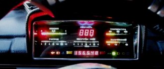
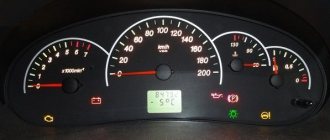
Drivers are replacing their old dashboard with a business panel because of its attractive appearance. The second reason for the replacement is that the Gazelle Business dashboard has expanded functionality and more options for providing information about the operation of the car.
The Euro panel is equipped with two large dials for the speedometer and tachometer and two small ones, informing about the amount of gasoline and coolant temperature. The remaining indicators are located in the center.
The simplicity of the euro panel makes it easier for the driver to perceive information. The disadvantage of the new panel is the complexity of installation. True, the pinout is contained in the instructions. If a car enthusiast has experience in such work, then it will not be difficult for him to install a new device.
Pinout of the Gazelle instrument cluster
Restyled version
Since 2003, cars began to be equipped with a new instrument cluster with an electronic speedometer. The new Gazelle speed sensor was designated DS-6 and was installed on the gearbox housing on the left side. The sensor had a mechanical drive similar to a cable. The same device was used at Gazelle Business.
The operation of the sensor is based on the Hall effect principle. Any change in speed is recorded by a sensor and transmitted in the form of voltage pulses to the controller of the electronic control unit. They have a lower limit of about 1 Volt and an upper limit of at least 5 Volts.
There is a proportional relationship between the speed and pulse frequency, so the sensor error is small. As the speed increases, the pulse frequency also increases, but the sensor has a design limitation - the pulse counter readings cannot be higher than 6004 per kilometer. The controller calculates the speed based on the number of pulses and the time intervals between them. The received signal is transmitted to the speedometer located on the dashboard of the car. The photo shows the electronic sensor of the Gazelle.
The design of the sensor is quite simple and, in general, it does not cause problems for car owners. Replacing the Gazelle Business speed sensor is quite simple. Before starting work, it is advisable to disconnect the battery from the vehicle's on-board network. To remove the sensor, it is necessary to remove the hatch located next to the gear shift lever. The sensor can also be accessed from below. To loosen the fastening nut, a wrench with a jaw size of 22 mm is required. After loosening the nut, the sensor can be easily unscrewed by hand and removed from the drive. On the other hand, it is equipped with a regular connector with plastic latches.
Sometimes there is an oil leak through the sensor drive, which oils the contacts and disrupts operation. The drive itself is fixed with a clamping bracket, to remove which you need to unscrew one 10 mm bolt. After this, the drive can be removed from the box housing to replace the ring rubber gasket.
Diagram and contacts of the Gazelle instrument cluster
1 Coolant temperature sensor 2 Emergency coolant temperature selection 3 Emergency low engine oil pressure 4 Oil pressure sensor 5 Fuel level sensor 6 ———- 7 ———- 8 Open bus doors 9 ———- 10 Open interior doors, hood or trunk 11 ——— 12 ——— 13 Malfunction of the electronic brake force control (EBD)
1 Battery 2 Right side turn signal lamps on 3 Left side turn signal lamps on 4 Parking brake on 5 High beams on 6 Front fog lights on 7 Gearbox illumination 8 Side lights on 9 Rear fog lights on 10 ——— 11 Center differential lock on 12 Downshift 13 Type of oil pressure sensor
1 Housing for analog signals 2 Ignition 3 Housing 4 High-voltage tachometer input 5 Low-voltage tachometer input 6 Low beam headlights on 7 Low battery 8 Ignition 9 Low brake fluid level 10 Speed sensor 11 Speedometer output to on-board computer 12 Heated rear window on 13 Anti-lock brake malfunction brake systems (ABS)
1 Diagnostic indicator (-) 2 Diagnostic indicator (+) and activation of engine preheating (+) 3 Wear of brake linings 4 Activation of engine preheating (-) 5 ————- 6 ————- 7 ————- 8 ————- 9 ————— 10 ————- 11 Windshield washer fluid level low 12 Coolant level low 13 Engine oil level low
The pinout of the device combinations of the 38.3801 family in various versions is shown in the table:
Old type instrument cluster 384.3801-10
New type instrument cluster 385.3801-10
Speed sensor connection diagram
In the graphical representation of the automotive system, you can see that three wires extend from the desired analyzer. In most cases this is the case, except for some brands of cars that use four-wire analyzers.
Let's return to the three-wire option:
The speed sensor connection diagram may, at first glance, seem complex and confusing. But, if you make a little effort and study it along with the instructions, then understanding this interweaving of wires and connections will not be difficult. And the resulting knowledge can greatly facilitate future repairs and maintenance of your car.
Installing and removing the torpedo
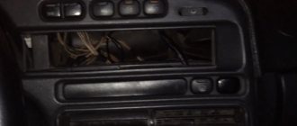
The dashboard is included in the Euro kit for Gazelle. On the latest versions it is installed at the factory. Drivers of older models also want to upgrade their dashboard. Replacing the device is not difficult: the design of the fasteners is almost identical, and the panel seat is the same in size.
Replacing a torpedo entails significant alterations, since it differs in both the shape and design of the fastenings. The car owner has to think about what changes to make himself. Sometimes, to repair the stove, you have to completely dismantle the torpedo. To do this, you need to know how to remove and install the torpedo back. For this procedure you need to prepare a set of keys and screwdrivers. An assistant may be needed.
Installation
To install the panel, you must remove the old shield. To do this, you need to dismantle the steering wheel using a special puller and unscrew a couple of screws of the decorative lining of the dashboard. You should also unscrew the bolts securing the tidy itself.
To do this you will need a 8" head. After this, you can remove the old panel and put a new one in its place. But as we said earlier, simply switching the connectors will not work. You need a pinout for the Gazelle Business instrument panel. There are four pads in total - XP1, 2, 3 and 4. Let's look at how to connect each:
- XP1. The first, fifth, sixth, seventh contacts are connected to ground. As for the rest, they connect to the sensor signals. The first contact is the air damper closing relay, the third is the DTOZH, the ninth and eleventh are the oil pressure and fuel level sensors in the tank, respectively. The remaining contacts are “Reserve”. We do not touch them and do not connect anything to them.
- XP2. Contacts number two, four, nine are connected to ground. The “plus” terminals are all from the fifth to the thirteenth.
- HRZ. Terminals two and thirteen are connected to the +12V positive contact. The first, eighth and twelfth terminals are connected to ground. The sixth connector is the speedometer speed sensor, the ninth is the ignition coil, the eleventh goes to the engine control unit.
- XP4. Here, almost all contacts need to be connected to ground. This applies to connectors from the first to the seventh inclusive. Only the sensor for the presence of water in the fuel filter (if there is one) and the glow plug switch are positive. These are connectors number eight and nine respectively.
t
