Removal, installation and troubleshooting of the gas tank on VAZ 2108, VAZ 2109, VAZ 21099 cars
If a fuel leak is detected from the gas tank, it is recommended to replace the gas tank. If the fuel pump screen often becomes clogged, you should remove and wash the gas tank. If a leak is detected along the junction of the upper and lower parts of the gas tank, you can solder these places (it is recommended to do this in specialized workshops). To do this, pour out the remaining gasoline, thoroughly rinse and dry the gas tank. Then seal the leak with soft solder.
WARNING Only a thoroughly washed and dried gas tank that does not contain gasoline vapors can be soldered, otherwise the vapors may ignite during soldering. To flush the gas tank, use Lobomid, MS or ML detergents. Then, to remove any remaining detergent, rinse and steam the gas tank with hot water. Dry the gas tank thoroughly. Before removing the gas tank from a VAZ 2108, VAZ 2109, VAZ 21099 car, disconnect the wire from the “-” terminal of the battery.
USEFUL ADVICE It is recommended to remove the gas tank on VAZ 2108, VAZ 2109, VAZ 21099 cars with an assistant.
1. Fold back the rear seat cushion and unscrew the cut-out part of the sound insulation.
2. Unscrew the two screws securing the gas tank hatch cover.
3. Remove the gas tank hatch cover with the rubber gasket.
4. Disconnect the block with wires from the fuel level sensor.
5. Unscrew the nut securing the fuel level sensor, under which the ground wire is secured.
6. Remove the wire from the stud. The remaining operations are carried out under the bottom of the car VAZ 2108, VAZ 2109, VAZ 21099.
7. Loosen the clamp of the gas tank filler pipe hose.
8. Disconnect the hose from the gas tank filler pipe.
9. Loosen the clamp and disconnect the air release hose from the fitting on the gas tank.
10. Loosen the clamp and disconnect the separator hose from the fitting on the gas tank.
11. Loosen the clamps and disconnect the hoses from the fuel lines.
12. Holding the gas tank, unscrew the two bolts of the gas tank securing clamps.
13. Move the clamps down while supporting the gas tank. Bend the clamp on the left side behind the resonator pipe.
14. Lower the front end of the gas tank down and remove the gas tank from the VAZ 2108, VAZ 2109, VAZ 21099. Drain the remaining gasoline from the gas tank.
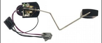
15. Unscrew the five remaining nuts securing the sensor and remove the fuel level indicator sensor from the gas tank.
16. Remove the fuel gauge sensor gasket.
17. Inspect the gas tank along the line where the upper and lower parts meet. If you find a leak, pour out the remaining gasoline, thoroughly rinse and dry the gas tank. Then solder the leak with soft solder. If necessary, glue the torn rubber gaskets on the gas tank.
18. Connect an ohmmeter to the contacts of the fuel level indicator sensor and check the resistance of the sensor at three float positions. In the lowest position (empty gas tank) the resistance should be 315-345 Ohms, in the middle position (gas tank half full) -108-128 Ohms, in the highest position (full gas tank) - no more than 7 Ohms. If the resistance is different from the specified value, replace the fuel level sensor.
19. Wash the dirty filter. Shake the float. If there is gasoline in it, then the float is leaking. We recommend replacing the float.
20. To replace the gas tank mounting clamps, remove the clamps from the brackets on the body and install new ones.
21. Assemble and install the gas tank on a VAZ 2108, VAZ 2109, VAZ 21099 car in the reverse order. Before installing the gas tank, remove the fuel level sensor wires inside the body.
Fuel tank of VAZ 2108, VAZ 2109, VAZ 21099 (bottom front view)
1 — fuel tank; 2 — fuel drain line; 3 - fuel supply line
Fuel tank of VAZ 2108, VAZ 2109, VAZ 21099 (bottom rear view)
1 — air release hose; 2 — separator hose; 3 - filling pipe hose
Varm › Blog › Conversion of VAZ 2108 and 2109 from carburetor to injector (theory)
Converting a carburetor VAZ to an injection one is not as scary as it seems at first glance. Provided that you have at least a basic understanding of your car. Here we will describe the independent modification of the power supply system and the list of required components.
Many car owners are dissatisfied with the power system of their favorite car. Someone, having suffered with an injector, dreams of a carburetor. And someone, on the contrary, is tired of cleaning the carburetor and selecting jets, and sees in a dream an almost trouble-free injector.
Initial data: - regular VAZ 21083, date of birth - December 1999.
Let's start with choosing an injection system and selecting the necessary spare parts. Having estimated their approximate cost (the most painful issue!), we decided to settle on an injection system based on the “Bosch” M 1.5.4 controller without an oxygen sensor and neutralizer, which meets Russian requirements for toxicity standards R-83. Moreover, there are many versions of the “Sport” PROM for this controller floating around Russia, so there will be enough scope for experiments.
I will say right away that the power system was assembled from factory spare parts, without making any changes to the design. For example, it was possible not to change the gas tank and fuel line, but to install an external electric fuel pump, for example from the Volga, and make all fuel connections using clamps, like on most foreign cars. Accordingly, the funds were spent to the maximum. Although, on the other hand, spare parts from General Motors (GM), famous not only for their reliability, but also for their price, were not used.
First of all, we purchase spare parts that practically do not fail on production cars: receiver, intake manifold, fuel line, gas tank, air filter housing, etc. The rest of the little things are “consumables”; all shops and markets without exception are filled with them.
Successful, in my opinion, was the purchase in Tolyatti of a kit consisting of mounted cylinder head units (receiver, manifold, throttle pipe, fuel rail with injectors, gaskets, fasteners, etc.), especially at a very low cost.
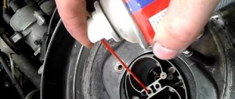
Next, we carry out some work before disassembling the old system. For example, we wash a new gas tank, dry it and install an electric fuel pump in it. Do not forget to align the arrows on the tank and the fuel pump housing, and also check the ease of movement of the fuel level sensor float. In addition, I recommend covering the gas tank with anti-corrosion mastic such as “Cordon”.
We begin the work by drilling two holes in the cylinder block: the first for the knock sensor, the second for mounting the ignition module bracket, and cutting the internal thread. Carefully inspect the cylinder block; these holes may have already been drilled at the factory; otherwise, special castings have been made for them. Drill carefully, otherwise you will sew through the block. The depth of the hole for the knock sensor is 16 mm, for the bolt securing the upper point of the ignition module bracket is 20 mm. Naturally, for this operation you need to drain the antifreeze and remove the radiator, bumper and queen. I didn’t dare drill holes myself; I entrusted this operation to a master from a body shop. The knock sensor has a tapered thread, so we tighten it until it stops...
Replacing the fuel rail on VAZ 2108, VAZ 2109, VAZ 21099
Welcome! The fuel rail is a very important thing because there are injectors on it; if you remove the ramp, then you will remove the injectors from the car engine and thus the car will no longer start, therefore, without a ramp on injection cars in which fuel is supplied under high pressure (Approximately 284- 325 kPa) cannot be avoided and if the ramp, for example, is clogged (This happens over time and mainly depends on the quality of gasoline that was poured into the car engine before the clogging), then the car will drive worse, and all this because the fuel to the injectors will be worse therefore, you need to not only monitor the condition of the ramp, but simply make sure that it is in normal condition and the rubber cap that closes the fitting of the ramp (What kind of cap is this as you read the article) was always on it and was removed only in cases of checking the fuel pressure on the ramp.
Note! To carry out the operation of replacing the ramp with a new one, you will need to stock up on: A set of wrenches, as well as a “5” hex key, you need to stock up since the ramp is mounted on bolts with hex heads and you will also need two screwdrivers, one of which will be a flat type , and another cross-shaped but flat one may not even be needed!
How to replace the fuel rail on a VAZ 2108-VAZ 21099?
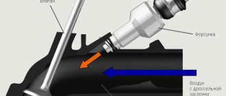
Removal: 1) Before starting the operation, you will need to do two things so that the ramp can be removed without unnecessary inconvenience and problems, namely, remove the minus terminal from the battery; this does not affect convenience in any way; you will simply protect the wiring from a short circuit if water suddenly gets into it (For information on how to remove the terminal, read the article: “Replacing the battery on a car”, study the first point in this article), after you have removed the terminal, proceed further, namely, for the convenience of removing the ramp, remove the air intake hose from the car engine (This hose indicated in the photo below with a red arrow), to remove it, loosen the two tightening screws with a screwdriver (indicated by blue arrows) and then remove it from the car, but the crankcase ventilation hose will not be completely removed, so also use a screwdriver to loosen the tightening screw of the crankcase ventilation hose ( Indicated by a green arrow) and then disconnect the hose from the air pipe and completely remove the pipe itself.
2) Now disconnect by hand the vacuum hose (Indicated by a red arrow) from the fuel pressure regulator (see photo below, this regulator is located on the ramp itself) and after disconnecting, release the pressure in the fuel system, for more details on how to do this, read the article called which: “Bleeding the fuel pressure on the VAZ.”
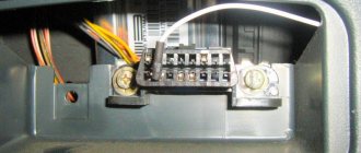
3) Then disconnect the fuel pipes from each other (There are only two pairs of them, see photo 1 in which only one pair of pipes is shown), to do this, use a wrench to unscrew them by the nuts and disconnect them from each other and do the same with the other pair of pipes, from the pipes Most likely, a little gasoline will spill out so that it does not get on the engine (You never know, if gasoline gets on something very hot, the car may even catch fire, so follow the fire safety rules) put a thick cloth under the place where the gasoline will flow, and then disconnect the block wires with a connector (see photo 2), and unscrew the screw that secures the pressure plate and then remove the plate (see photos 3 and 4).
4) Let's go further, now unscrew the two bolts that have hex heads and which secure the ramp itself to the car engine, one of the ramp mounting bolts is indicated by an arrow just below for clarity (This is the right bolt if you look in the direction of the car).
Fuel hoses VAZ 2109 injector
Finally, I completed one of the most difficult stages in converting to an injector, this is installing the lines and tank.
IMHO! Well, if, after all, you, the reader, decide to open this necessary cart, sit comfortably on your fifth point to get at least a little pleasure)))
Perhaps the story should begin with a return to the past, or rather about the purchase of a tank. After the purchase, the tank was cleaned both inside and out. Then my favorite zincari was used...
Then we move to the garage, where we prime and paint the tank
We could have stopped at this point in pampering with the tank, but that’s not for us. I also decided to cover it with rubber mastic.
At the same time I glued rubber bands to it
Next we plug in the fuel pump with the FLS you need. Now we're done with the tank, IT'S BETTER TO TAKE A TANK WITH M6 STUDS
, they are welded through spacers, if they break off, it’s easier to attach a new one.
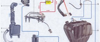
For clarity, we take this diagram and begin to stick tubes and hoses into it; I assembled it according to it, with the exception of the gravity valve (I decided not to stick it in).
Here's everything you need to pull hoses and lines (the lines themselves are not shown in the photo)
We pull off the old tank and neck and begin to pull the tubes according to the diagram
Of course, there are no photos of the process, and it’s impossible to really take it, it’s too stormy))) In general, everything turned out as it should:
I pulled 3 tubes: - forward - return - tube under the adsorber (I took a pipe from the carb and extended it with a hose) A logical question, why am I bothered with this adsorber? I’ll say this clearly not because of the environment, but because it allows you to save 3- 5% gasoline, which I wrote about here
Next, we plug in the hoses for the fuel filter (initially I thought that they wouldn’t fit, but when I stuck the tank in its rightful place, everything fit as it should!). IMPORTANT TO HAVE STUDS LIKE THIS
.
under the filter bracket mount, although you can move the filter under the hood either with self-tapping screws or weld it in. I’m talking about studs
.
When twisting the line fittings, do not forget to put the rubber rings on the dad
. It’s better to put the wiring under the EBN right away, then it’s probably not realistic to plug it in, or you need thin hands with long and tenacious fingers
Well, now we just grab the hoses to the separator with ties, adjusting the length of the hose so that it doesn’t get too tight
This is where we can finish with the fuel wires. The task is quite difficult, without a pit (even the weakest one) it is not possible to do it at all, and the assistant is sometimes very relevant. I fiddled with all this for 2 days.
Fuel circulation in the vehicle’s fuel system is carried out through pipelines connecting the tank, filters, pumps, carburetor or ramp, injectors, etc. The elasticity of pipelines is ensured by hoses - read the article about these components of VAZ cars, their types, design and features.
Design features of the VAZ-2109 fuel system
The fuel supply is located in the tank located under the bottom in the area of the rear seats. The tank is made of steel and consists of two stamped halves welded together.
Through drainage tubes it is connected to a non-separable separator that traps gasoline vapors. The latter communicates with the atmosphere through a double check valve, which prevents excessive increase or decrease in pressure in the fuel tank.
The filler neck is connected to the tank with a gas-resistant rubber hose secured with clamps.
The plug is sealed. Through a fuel intake with a mesh filter, gasoline is supplied from the tank through steel fuel lines and rubber gas-resistant hoses to a fine fuel filter, a fuel pump and then to the carburetor.
Gasoline is sucked from the tank due to the vacuum created by the gasoline pump.
Fine filter – with a paper filter element in a plastic housing, non-separable design.
There is an arrow on the filter housing that must coincide with the direction of fuel movement.
The fuel pump is a diaphragm type, mechanically driven by the camshaft eccentric, with a manual pumping lever.
It consists of a lower housing with drive levers, an upper housing with valves and pipes, a diaphragm assembly and a cover.
The diaphragm assembly is installed between the upper and lower housings.
Two diaphragms are installed on top (working ones), and one (safety) on the bottom: it prevents gasoline from entering the engine crankcase if the working diaphragms rupture.
In this case, leaked gasoline is discharged through holes in the external spacer located between the safety and working diaphragms.
The diaphragms, together with the internal gasket and plates (from the outside), are assembled on the rod and secured with a nut.
The rod is inserted into the cavity of the balancer using a T-shaped shank.
A spring is installed between the diaphragm assembly and the lower housing.
The upper housing is closed with a lid secured with a bolt. Underneath there is a mesh fuel filter.
The pump is attached to the engine on two studs through a heat-insulating spacer, sealed on both sides with cardboard gaskets.
Gaskets are available in thicknesses of 0.30, 0.75 and 1.25 mm.
A 0.30 mm gasket is installed between the heat-insulating spacer and the engine, and a 0.75 mm gasket is installed on the outer side of the spacer (facing the fuel pump) and the minimum protrusion of the pusher from the spacer is checked, which should be 0.8 - 1.3 mm.
To do this, slowly turn the engine crankshaft, pressing the pusher with your finger and periodically checking its protrusion above the plane of the gasket.
If the minimum protrusion is less than specified, the outer gasket is replaced with a thinner one, if more, with a thicker one.
Part of the gasoline supplied to the carburetor is drained back into the tank through a system of pipelines and hoses - this improves the cooling of the gasoline pump and prevents the formation of vapor locks in the power system.
A check valve is embedded in the drain line, allowing fuel to flow in only one direction - from the carburetor to the tank.
The air filter housing can receive cold air through an intake near the radiator or hot air from an intake mounted on the exhaust manifold.
The flow is switched by a damper controlled by a thermostat.
The built-in thermal power element opens the hot air damper when the incoming air temperature is below 25°C and completely closes it if the air is heated above 35°C.
Thus, the temperature of the incoming air is automatically maintained within 25-35°C.
Power supply system for VAZ-2108, -21081, -21083 engines
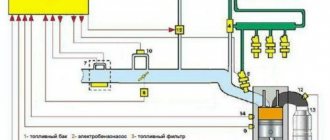
Carburetor engine power system
1 — fine fuel filter; 2 – fuel supply hose to the fuel pump; 3 – fuel pump; 4 – heated air intake; 5 – check valve; 6 – fuel drain hose from the carburetor; 7 – cold air intake; 8 – thermostat; 9 – air filter assembly; 10 – carburetor; 11 – fuel drain pipe; 12 – fuel supply pipe from the tank; 13 – fuel tank; 14 – flange of the fuel level sensor and fuel intake tube; 15 – separator hose; 16 – filling pipe hose; 17 – filling pipe; 18 – fuel tank plug; 19 – separator; 20 – two-way valve hose; 21 – two-way valve
Checking the power system
Remove the air filter housing cover by unscrewing the nut with a 10 mm wrench and unfastening the spring clips. Remove the air filter.
Unscrew the four nuts with a size 8 wrench, use a screwdriver to loosen the clamp of the crankcase ventilation hose at the connection point to the valve cover and remove the air filter housing.
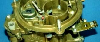
Look inside the carburetor.
The primary choke should be completely closed if the engine is cold, and fully open if the engine is warm or hot.
In the first case, open the air damper.
Press the carburetor throttle valve actuator with your hand.
If a stream of gasoline appears from the accelerator pump nozzle, then there is gasoline in the carburetor
In order to be completely sure that there is gasoline in the carburetor, it is necessary to unscrew the five screws securing the top cover of the carburetor, the screw securing the bracket for the choke control cable sheath and remove the wire from the idle speed solenoid valve.
Very carefully, without allowing lateral movements, lift the carburetor cover.
The gasoline level should be approximately 22–23 mm below the connector of the carburetor cover and body
Place the carburetor cover in place and tighten it with 2-3 screws diagonally.
Get behind the wheel, smoothly pressing the gas pedal, turn on the starter and start the engine.
Replace the carburetor cap without securing it. Carefully insert the screwdriver into the connector of the cover and housing.
Try manually pumping gas. If it fails, turn the crankshaft a little with the starter and try again.
If the carburetor begins to intensively fill with gasoline, put the carburetor cover in place and press it with 2-3 screws diagonally. Try starting the engine.
If the engine starts, the carburetor needle valve hangs.
If you cannot pump gasoline manually, reassemble the carburetor and use a screwdriver to loosen the clamp of the rubber hose supplying gasoline to the carburetor.
By turning the hose from side to side, pull it off the carburetor fitting.
Place the end of the hose in an empty plastic bottle to avoid flooding the engine with gasoline.
Press the manual fuel pump lever.
Turn the engine shaft a little with the starter and try again.
Using a 13mm wrench, unscrew the carburetor fine filter holder.
Carefully, being careful not to damage it, remove the fine filter from the carburetor cover
Don't lose the copper O-ring
Inspect the filter carefully. If it is clogged with dirt, replace it or, as a last resort, try washing it with gasoline and blowing it with compressed air.
To watch online, click on the video ⤵
Replacement of fuel pipes (VAZ 2115) More details
Replacement of fuel and brake pipes VAZ 2114,2110-12. More details
Replacing fuel pipes (fuel lines) on an old-style Chevrolet Niva Read more
Fuel and brake lines VAZ 21099 Read more
Replacement of fuel pipes VAZ 2112 1.5 16 cells. with your own hands. More details
Replacement of brake pipes VAZ 2109 (Lada Samara) More details
THE rarest part on a VAZ 2110. Replacement of the fuel line. More details
New fuel system for carb 2109 Swap V16 PART 5 Read more
Installation of the tank and fuel pipes. More details
Replacing the fuel line Read more
How to repair a fuel system pipe? More details
Replacing brake pipes. Brake tube replacement Read more
Fastening the fuel wires. More details
replacement of fuel line VAZ 2110 Read more
We make brake and fuel pipes using heat shrink for BMW e34 540 Installing copper pipes Read more
START OF ASSEMBLY OF VAZ 21099!! Treated the bottom. New fuel line and brake lines!! More details
Replacement of fuel line NivaChevrolet (Old model) More details
Injector for VAZ. Part 4. Fuel line part 1 Read more
Replacing brake pipes. Important points! More details