In this article, we will look at the fundamental differences between synchronous and asynchronous electric motors, so that everyone reading these lines can clearly understand these differences.
Asynchronous electric motors are more widespread today, however, in some situations, synchronous motors turn out to be more suitable, more efficient for solving specific industrial and production problems, this will be discussed below.
First of all, let's remember what an electric motor is. An electric motor is an electrical machine designed to convert electrical energy into mechanical energy of rotation of the rotor, and serving as a drive for some mechanism, for example, to drive a crane or pump.
Back in school, everyone was told and shown how two magnets repel with like poles, and unlike poles attract. These are permanent magnets. But there are also variable magnets. Everyone remembers the drawing with a conducting frame located between the poles of a horseshoe-shaped permanent magnet.
A horizontally located frame, if a direct current is passed through it, will begin to rotate in the magnetic field of a permanent magnet under the influence of a pair of forces (Ampere's Force) until equilibrium is achieved in a vertical position.
If you then pass a direct current in the opposite direction through the frame, the frame will turn further. As a result of this alternating supply of the frame with direct current, first in one direction, then in the other, continuous rotation of the frame is achieved. The frame here is an analogue of an alternating magnet.
The example given with a rotating frame demonstrates in its simplest form the principle of operation of a synchronous electric motor. Any synchronous electric motor has field windings on the rotor, which are supplied with direct current, which forms the magnetic field of the rotor. The stator of a synchronous electric motor contains a stator winding to form the stator magnetic field.
When alternating current is supplied to the stator winding, the rotor will rotate at a frequency corresponding to the frequency of the current in the stator winding. The rotor rotation frequency will be synchronous with the frequency of the stator winding current, therefore such an electric motor is called synchronous. The rotor magnetic field is created by the current, and not induced by the stator field, so a synchronous motor is able to maintain synchronous rated speeds regardless of the load power, of course, within reasonable limits.
An asynchronous electric motor, in turn, differs from a synchronous one. If you remember the drawing in the frame, and the frame is simply short-circuited, then when the magnet rotates around the frame, the current induced in the frame will create a magnetic field of the frame, and the frame will try to catch up with the magnet.
The rotation frequency of the frame under mechanical load will always be less than the rotation speed of the magnet, and the frequency will therefore not be synchronous. This simple example demonstrates the principle of operation of an induction motor.
In an asynchronous electric motor, the rotating magnetic field is formed by the alternating current of the stator winding located in its slots. The rotor of a typical induction motor does not have any windings, but instead contains short-circuited bars (a squirrel cage rotor), called a squirrel-cage rotor. There are also asynchronous motors with a wound rotor, where the rotor contains windings, the resistance and current in which can be controlled by a rheostat.
So, what is the fundamental difference between an asynchronous electric motor and a synchronous one? In appearance, they are similar in appearance; sometimes even a specialist cannot distinguish a synchronous electric motor from an asynchronous one by external signs. The main difference lies in the design of the rotors. The rotor of an asynchronous electric motor is not powered by current, and the poles on it are induced by the magnetic field of the stator.
The rotor of a synchronous motor has an excitation winding with independent power supply. The stators of a synchronous and asynchronous motor are designed in the same way, the function in each case is the same - creating a rotating magnetic field of the stator.
The revolutions of an asynchronous motor under load always lag behind the rotation of the stator magnetic field by the amount of slip, while the revolutions of a synchronous motor are equal in frequency to the “revolutions” of the stator magnetic field, so if the revolutions must be constant under different loads, it is preferable to choose a synchronous motor, for example in When driving guillotine shears, a powerful synchronous motor will best cope with its task.
Some compressors and pumps require a constant rotation speed at any load; synchronous electric motors are installed on such equipment.
Synchronous motors are more expensive to manufacture than asynchronous ones, so if you have a choice and a slight decrease in speed under load is not critical, purchase an asynchronous motor.
Synchronous electric motors are widely used in electric drives that do not require speed control. Compared to asynchronous motors, they have a number of advantages:
higher efficiency;
the ability to manufacture engines with low rotation speeds, which eliminates the need for intermediate gears between the engine and the working machine;
the engine speed does not depend on the load on its shaft;
Possibility of use as reactive power compensating devices.
Synchronous electric motors can be consumers and generators of reactive power. The nature and value of the reactive power of a synchronous motor depend on the magnitude of the current in the field winding. The dependence of the current in the winding that supplies voltage to the electrical network on the excitation current is called the U-shaped characteristic of a synchronous motor. At 100% load on the motor shaft, its cosine phi is equal to 1. In this case, the electric motor does not consume reactive power from the electrical network. The current in the stator winding has a minimum value.
What is the difference between asynchronous and synchronous motors
Electric motors can be divided into two main categories - synchronous and asynchronous (induction) motors. These two types are quite different from each other. The difference is already visible in the names themselves. You can distinguish the units by the number of revolutions stamped on the nameplate (if the type of motor is not indicated there); an asynchronous motor has an unrounded number (for example, 950 rpm), and a synchronous motor has a rounded number (1000 rpm).
There are other important differences, in this article we will look at the most significant of them: design, performance and price.
Differences in operation and cost
Any engine consists of two elements: stationary and rotating. The stator has axial slots - grooves, on the bottom of which current-carrying copper or aluminum wires are laid. The electric motor has a rotor with an excitation winding attached to the shaft.
The fundamental difference between synchronous and asynchronous motors is the rotors, or more precisely, their design.
In synchronous models at low powers they are permanent magnets.
Alternating voltage is supplied to the stator winding, the rotor is connected to a constant power source. The direct current passing through the field winding induces a magnetic field in the stator. The torque is created due to the lag angle between the fields. The rotor has the same speed as the stator's magnetic field.
The units are used in practice both as generators and as engines.
Asynchronous models are fairly inexpensive motors that are used frequently and everywhere. They are simpler in design, despite the fact that the fixed parts of all motors are basically similar.
An alternating electric current is passed through the stator winding, which interacts with the rotor winding. The two fields rotate at the same speed in the same direction, but cannot be equal, otherwise the induced emf and, especially, the torque would not be created. This causes the occurrence of an induced current in the rotor winding, the direction of which, according to Lenz's rule, is such that it tends to oppose the cause of its production, i.e., the sliding speed.
The rotation speed of the rotor does not coincide with the speed of the magnetic field; it is always less. Thus, the rotor tries to catch up with the speed of the rotating magnetic field and reduce the relative speed.
Switched reluctance motors
A switched reluctance motor (SRM) creates torque by attracting the magnetic fields of the rotor teeth to the magnetic field of the stator. Switched reluctance motors (WRM) have a relatively small number of stator winding poles. The rotor has a toothed profile, which simplifies its design and improves the generated magnetic field, unlike reluctance synchronous machines. Unlike synchronous reluctance motors (SRM), WRMs use pulsed DC excitation, which requires a special converter for their operation.
To maintain the magnetic field in the VRM, excitation currents are required, which reduces the power density compared to electric machines with permanent magnets (PM). However, they still have smaller overall dimensions than conventional ADs.
The main advantage of switched reluctance machines is that the magnetic field weakens naturally when the excitation current decreases. This property gives them a great advantage in the control range at speeds above the nominal (the range of stable operation can reach 10:1). High efficiency is present in such machines when operating at high speeds and with low loads. Also, VRDs are capable of providing surprisingly constant efficiency over a fairly wide control range.
Switched reluctance machines also have fairly good fault tolerance. Without permanent magnets, these machines do not generate uncontrolled current and torque during malfunctions, and the independence of the VRM phases allows them to operate with a reduced load, but with increased torque ripples when one of the phases fails. This property can be useful if designers want increased reliability of the system being developed.
The simple design of the VRD makes it durable and inexpensive to manufacture. No expensive materials are used in its assembly, and the non-alloy steel rotor is excellent for harsh climate conditions and high rotation speeds.
A VRD has a power factor lower than PM or IM, but its converter does not need to create a sinusoidal output voltage for the machine to operate efficiently; accordingly, such inverters have lower switching frequencies. As a result, lower losses in the inverter.
The main disadvantages of switched reluctance machines are the presence of acoustic noise and vibration. But these shortcomings can be combated quite well by more carefully designing the mechanical part of the machine, improving electronic control, and also mechanically combining the engine and the working body.
VFDs are well suited for a wide range of applications and are increasingly used for processing heavy-duty materials due to their high overload capacity and wide speed control range. Their high overload capacity makes them increasingly attractive for use as traction electric drives for modern electric vehicles. Also, VFDs are widely used in electrical appliances.
Which unit is better
In conclusion, it should be noted that it is impossible to say that one motor is better than another. However, asynchronous models are more reliable in operation and are simpler in design. If the units are not overloaded, then the user can be satisfied with their long service life.
The advantage of the synchronous model is that it is easy to set a high power factor. Therefore, the model is much more efficient, but the price will be correspondingly more expensive. The machines are used in systems with a required power of 100 kW or more.
Source
What is a synchronous motor?
Synchronous to be electric motors that operate on alternating current and have a rotor with a rotation speed that matches the speed of the magnetic field in the unit design.
Key elements of a synchronous electric motor:
The first element of the unit is located on the stator. The inductor is placed on the rotor, which is separated from the stator by an air gap. The armature structure is represented by a winding (one or more). The currents that are supplied to the corresponding motor element form a magnetic field that rotates at a given frequency and interacts with the field of the inductor. The inductor includes 2 poles - in the form of permanent magnets.
The synchronous unit can operate in two modes:
The first operating mode involves the interaction of the magnetic field formed at the armature and the field that forms at the poles of the inductor. A synchronous motor in generator mode operates due to electromagnetic induction: during the rotation of the rotor, the magnetic field that is formed on the winding interacts in turn with the phases of the winding on the stator, resulting in the formation of an electromotive force.
What is an asynchronous electric motor?
Asynchronous as electric motors in which the rotational speed of one of the key elements - the rotor - does not coincide with the rotational frequency of the magnetic field formed by the current that occurs on the stator winding. Asynchronous units are sometimes called induction units. This is due to the fact that current is induced in the rotor winding when exposed to the stator magnetic field.
The design of an asynchronous electric motor contains a stator and a rotor, which are separated by an air gap. Main active elements of the unit:
An important role in the functioning of an asynchronous motor is played by additional structural elements that provide strength, cooling and stable operation of the unit.
What is a commutator motor?
The length of a DC motor depends on the class. For example, if we are talking about a 400 class engine, then its length will be 40 mm. The difference between commutator electric motors and their brushless counterparts is their ease of manufacture and operation, and therefore their cost will be lower. Their feature is the presence of a brush-commutator unit, with the help of which the rotor circuit is connected to the chains located in the stationary part of the motor. It consists of contacts located on the rotor - a commutator and brushes pressed to it, located outside the rotor.
Rotor
These electric motors are used in radio-controlled toys: by applying voltage from a DC source (the same battery) to the contacts of such a motor, the shaft is set in motion. And to change its direction of rotation, it is enough to change the polarity of the supplied supply voltage. Low weight and size, low price and the ability to restore the brush-commutator mechanism make these electric motors the most used in budget models, despite the fact that it is significantly inferior in reliability to a brushless motor, since sparking is possible, i.e. excessive heating of the moving contacts and their rapid wear when exposed to dust, dirt or moisture.
As a rule, a commutator motor is marked with a marking indicating the number of revolutions: the lower it is, the higher the shaft rotation speed. By the way, it is very smoothly adjustable. But, there are also high-speed engines of this type that are not inferior to brushless ones.
Comparison
The main difference between a synchronous motor and an asynchronous one is the relationship between the rotor speed and the magnetic field. In the first type of unit, both indicators are the same. In an asynchronous machine - different.
It can be noted that electric motors of the second type are generally more common than the first. At the same time, asynchronous units are most often presented in a variety in which a squirrel-cage rotor is installed. These devices have a number of important advantages over electric motors of other categories. Namely:
At the same time, asynchronous machines with a squirrel-cage rotor also have a number of disadvantages. Namely:
Synchronous jet motors
Synchronous reluctance motors are always paired with a frequency converter and use the same type of stator flux control as a conventional IM. The rotors of these machines are made of thin-sheet electrical steel with slots punched in such a way that they are magnetized less on one side than on the other. The rotor's magnetic field tends to "couple" with the rotating magnetic flux of the stator and creates torque.
The main advantage of reluctance synchronous electric motors is the low losses in the rotor. Thus, a well-designed synchronous reluctance machine operating with the right control algorithm is quite capable of meeting the European premium IE4 and NEMA standards without using permanent magnets. Reduced heat losses in the rotor increases torque and increases power density compared to asynchronous machines. These motors have low noise levels due to low torque ripple and vibration.
The main disadvantage is the low power factor compared to an asynchronous machine, which results in higher power consumption from the network. This increases the cost and poses a difficult question to the engineer, is it worth using a jet machine or not for a particular system?
The complexity of manufacturing the rotor and its fragility make it impossible to use jet motors for high-speed operations.
Synchronous reluctance machines are well suited for a wide range of industrial applications that do not require high overloads or high rotation speeds, and are increasingly being used for variable speed pumps due to their increased efficiency.
Methods for exciting synchronous generators
In synchronous generators, a contactless electromagnetic excitation system has also been used, in which the synchronous generator does not have slip rings on the rotor. B is used as an exciter
(Fig. 1.3, b).
The three-phase exciter winding 2
, in which an alternating EMF is induced, is located on the rotor and rotates together with the excitation winding of the synchronous generator and their electrical connection is carried out through a rotating rectifier
3
directly, without slip rings and brushes.
DC power supply of excitation winding 1
of exciter B is carried out from the subexciter
PV
- a direct current generator. The absence of sliding contacts in the excitation circuit of a synchronous generator makes it possible to increase its operational reliability and increase efficiency.
In synchronous generators, including hydroelectric generators, the principle of self-excitation has become widespread (Fig. 1.4, a), when the alternating current energy required for excitation is taken from the stator winding of the synchronous generator and through a step-down transformer and a rectifying semiconductor converter PP
converted to DC energy. The principle of self-excitation is based on the fact that the initial excitation of the generator occurs due to the residual magnetism of the machine.
In Fig. 1.4, b shows a block diagram of the automatic self-excitation system of a synchronous generator ( SG
) with a rectifier transformer (
VT
) and a thyristor converter (
TC
), through which alternating current electricity from the
SG
, after conversion to direct current, is supplied to the excitation winding.
The thyristor converter is controlled by means of an automatic excitation regulator ARV
, the input of which receives voltage signals at the input of
the SG
(through the voltage transformer
TN
) and the load current
of the SG
(from the current transformer
CT
).
The circuit contains a protection unit ( BZ
), which provides protection for the excitation winding (
OW
) from overvoltage and current overload.
The power spent on excitation usually ranges from 0.2 to 5% of the useful power (a lower value applies to high-power generators). In low-power generators, the principle of excitation by permanent magnets located on the rotor of the machine is used. This method of excitation makes it possible to rid the generator of the excitation winding. As a result, the design of the generator is significantly simplified, becoming more economical and reliable. However, due to the high cost of materials for the manufacture of permanent magnets with a large supply of magnetic energy and the complexity of their processing, the use of permanent magnet excitation is limited to machines with a power of no more than a few kilowatts.
Synchronous generators
form the basis of the electric power industry, since almost all electricity throughout the world is generated through synchronous turbo or hydro generators.
Synchronous generators are also widely used as part of stationary and mobile electrical installations or stations complete with diesel and gasoline engines.
Starting electric motors
Asynchronous electric machines with a power of up to 30-50 kW are started by direct supply of electricity. With high-power motors and synchronous machines the situation is more complicated.
Starting high power asynchronous motors
To start such machines, different methods are used:
Starting synchronous electric machines
Unlike asynchronous machines, which are started by the interaction of the stator field and the windings or squirrel cage of the rotor, a synchronous machine must first be accelerated to a speed close to synchronous.
Synchronous and asynchronous motor: differences
The difference between how engines work is in the rotor. In the synchronous type, it consists of a permanent or electric magnet. Due to the attraction of opposite poles, the rotating field of the stator also attracts the magnetic rotor. Their speed is the same. Hence the name - synchronous.
Asynchronous motors, in turn, are simple and reliable, but their disadvantage is the difficulty of adjusting the rotation speed. To reverse a three-phase asynchronous motor (that is, change the direction of its rotation in the opposite direction), the location of two phases or two linear wires approaching the stator winding is changed.
If we consider the rotation speed, then there are differences between synchronous and asynchronous motors. In the synchronous type, this indicator is constant, unlike in the asynchronous type. Therefore, the first is used where constant speed and complete controllability are required, for example, in pumps, fans and compressors.
It is very easy to detect the presence of the types of devices in question on a particular device. An asynchronous motor will have a non-round number of revolutions (for example, nine hundred and thirty per minute), while a synchronous motor will have a round number (for example, a thousand revolutions per minute).
Both motors are quite difficult to control. The synchronous type has a rigid mechanical characteristic: for any changing load on the motor shaft, the rotation speed will be the same. In this case, the load, of course, must change taking into account that the engine is able to withstand it, otherwise this will lead to breakdown of the mechanism.
This is how a synchronous and asynchronous motor works. The differences between both types determine the scope of their use; when one type copes with a task optimally, for the other it will be problematic. At the same time, you can also find combined mechanisms.
Replacing DC motors with AC induction motors
Industrial DC motors began to be produced in 1860-1870, which was preceded by a 30-year period of their development after the fundamental discoveries of M. Faraday (the law of electromagnetic induction and the conversion of electrical energy into mechanical energy).
DC motors are widely used in our time thanks to the use of modern thyristor converters, which allow the speed of these motors to be controlled by changing the voltage on the armature or in the field windings. To expand the range of speed control, various feedback signals are used (armature voltage, tachogenerators, etc.). However, the operation of DC motors entails a number of significant inconveniences associated with the design features of machines of this type, namely:
1. Complexity of the design and, as a result, high price 2. The presence of a brush-collector unit 3. Large mass 4. The need for periodic maintenance
All these disadvantages require significant costs when purchasing DC machines and their further operation, and they can also significantly reduce the reliability and accuracy of systems as a whole. It is necessary to plan additional preventative maintenance and stop production to service the brush-collector units and periodically blow dust off the machines.
Until recently, the introduction of asynchronous motors (IM) with squirrel-cage rotors into systems where a wide range of speed control is required was not possible, and switchable gearboxes or variators were used to change the speed of the driven mechanisms. A further development of such systems was the appearance of asynchronous motors with switching the number of poles (two and three-speed motors), which made it possible to change the rotation speed in steps.
With the development of semiconductor electronics (the development of IGBT transistors), it became possible to produce inexpensive microprocessor frequency converters, with the help of which it became possible to fully control the speed of asynchronous motors over a wide control range (1:1000). Now the rotation speed of the motor does not depend on the frequency of the supply network; the motors can be accelerated above their rated speed. It also became possible to control the torque of asynchronous motors. Motion control systems using asynchronous motors and frequency converters are cheaper and simpler than similar systems with DC motors. Digital devices (encoders) are widely used as feedback sensors, which are less susceptible to electromagnetic interference than tachogenerators classically used with DC machines.
An asynchronous motor is a simple, inexpensive, maintenance-free machine. It is these arguments that have led to the fact that in many enterprises, DC machines with thyristor converters began to be replaced with asynchronous motors with control systems built on frequency converters.
When selecting an asynchronous motor to replace a DC machine, it is necessary to take into account the difference in the characteristics of these machines. Engine selection is carried out according to the following parameters:
1. According to rated rotation speed
The range of change in the shaft speed of an asynchronous motor must be equal to or greater than that of a DC motor.
2. By torque (nominal, starting, maximum)
The rated torque of an asynchronous motor must be equal to or greater than the original one, subject to long-term operation in a given speed range without overheating. The maximum and starting torques must be equal to or greater than the starting torque defined for a given mechanism.
Figure 1 and 2 show the mechanical characteristics of an induction motor and a DC motor, respectively. As you can see, at low speeds an asynchronous motor has a torque significantly less than the rated one, unlike a DC motor. Therefore, when replacing a DC motor, it is necessary to clearly determine the shaft speed range and the required torque within this range. As a rule, to satisfy the mechanical characteristics of the drive mechanism, it is necessary to install an asynchronous motor of higher power.
Fig. 1 Mechanical characteristics of an asynchronous motor
Fig.2 Mechanical characteristics of a DC motor
3. By operating mode
The heating of an electric machine depends on its operating mode, i.e. on the ratio of the duration of periods of work and pauses between them, or periods of work with full or partial load, on the frequency of turning on the machine and the nature of the transient processes. The following operating modes are subdivided: Continuous mode (S1) - a mode in which the operating time of the machine at practically constant load and ambient temperature is sufficient to heat all its parts to a practically steady temperature. The mode is characterized by constant losses throughout the entire operating time of the machine.
Short-term mode (S2) - a mode in which periods of constant load alternate with periods of machine shutdown, and during operation the temperature of machine parts does not have time to reach a steady value, and during pauses the machine is cooled to a cold state.
Intermittent mode (S3-S8) - differs from short-term mode by the regulated duration of switching on under a constant load and the duration of shutdown periods, and the operating time of the machine is always less than the time required to heat its parts to a steady temperature, and the pause time is less than that required to cool the machine to practically cold. The difference between modes S3-S8 is the frequency of starts and the duration of the machine's activation.
4. According to operating conditions
According to GOST 17498-87, an asynchronous motor must have the appropriate degree of protection IPXX, where the first symbol X means the degree of protection of the shell from the penetration of foreign solids, the second symbol X means the degree of protection of the shell from the harmful effects of penetrating water. For example, IP54 - “The machine is not completely protected against the penetration of dust into the enclosure (however, dust cannot penetrate in sufficient quantities to impair the operation of the product) and water splashed onto the enclosure in any direction.”
For any questions regarding this application, please contact Drayvika LLC by phone. or Email
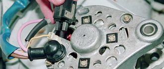
Design and principle of operation
The main driving force of any electric motor is electromagnetic induction. Electromagnetic induction, to describe it in a nutshell, is the appearance of current in a conductor placed in an alternating magnetic field. The source of the alternating magnetic field is a stationary motor housing with windings placed on it - a stator connected to an alternating current source. It contains a moving element - a rotor, in which current arises. According to Ampere's law, an electromotive force - EMF - begins to act on a charged conductor placed in a magnetic field, which rotates the rotor shaft. Thus, the electrical energy supplied to the stator is converted into mechanical energy by the rotor. Various mechanisms that perform useful work can be connected to the rotating shaft.
AC electric motors are divided into synchronous and asynchronous. The difference between them is that in the first, the rotor and the magnetic field of the stator rotate at the same speed, and in the second, the rotor rotates more slowly than the magnetic field. They differ both in structure and principle of operation.
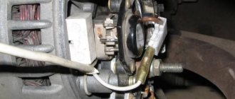
Asynchronous motor
Windings are attached to the stator of an asynchronous motor, creating an alternating rotating magnetic field, the ends of which are brought out to the terminal box. Since the engine heats up during operation, a cooling fan is installed on its shaft.
The rotor of an asynchronous motor is made with the shaft as a single unit. It consists of metal rods closed to each other on both sides, which is why such a rotor is also called a squirrel-cage rotor. In appearance, it resembles a cage, which is why it is often called a “squirrel wheel”. The slower rotation of the rotor compared to the rotation of the magnetic field is the result of power loss due to friction of the bearings. By the way, if there had not been this difference in speed, the EMF would not have arisen, and without it there would have been no current in the rotor and no rotation itself.
The magnetic field rotates due to the constant change of poles. In this case, the direction of the current in the windings changes accordingly. The rotation speed of an asynchronous motor shaft depends on the number of poles of the magnetic field.
Two types of AC motors
Asynchronous motors - naive simplicity
The rotor either catches up with the wave, or lags slightly behind, because it simply cannot run synchronously with it. This phenomenon was called “sliding”; having caught up with the running magnetic field, the squirrel cage rotor loses magnetic induction and then simply slides by inertia for some time. And when friction or load forces him to lag behind the running field, he will again “feel” in himself the changes in the lines of force of the field overtaking him and will again gain induction, and at the same time the strength to move.
Asynchronous motors
That is, the rotor slips slightly: it either catches up with the magnetic field running evenly in a circle, then it “forgets why it was running” and lags slightly behind, then it “comes to its senses” again and again tries to catch up. Gradually, these deviations stabilize - depending on the friction in the bearings and the magnitude of the load on the shaft - and the asynchronous motor begins to operate simply at a rotation speed slightly lower than the voltage frequency on the stator. This frequency difference is called the slip frequency.
Synchronous motors: complex in simple
In order for the rotor to be rigidly connected to the traveling wave of the magnetic field of the stator coils, a synchronous electric motor was invented. And the problem is easily solved. In the rotor, instead of a changing magnetic field from short-circuited squirrel cage currents, you need to use permanent magnets and their magnetic field.
Engine device
There are two options. Either this is the field from a permanent magnet fixed in the rotor, or this is the field from electromagnets installed in the rotor instead of such a magnet.
A regular magnet is, of course, simpler. But then, for the standard functioning of such electric motors, it is necessary that all of them - and thousands of electric motors are used - have exactly the same magnets. Otherwise, the movement parameters will be different, and the magnets still tend to demagnetize.
An electromagnet installed in the motor rotor is easier to make to produce a field of the required quality, but an electric current is required for its operation. This current, which is called the excitation current, in turn must be taken somewhere and somehow supplied to the rotor.
Synchronous electric motor (or generator)
1 – rotor, 2 – excitation collector
This is where some of the diversity in synchronous motor designs comes from. But the most important thing is that synchronous motors rotate their shaft strictly synchronously with the frequency of the field of stator coils running in a circle, that is, their rotation speed is exactly equal to - or a multiple (if there are more than three stator windings) - the frequency of the alternating current in the supply network.
However, among other things, a synchronous motor has the property of being completely reversible. Because a synchronous electric motor is the same generator of electric current, but working “in the opposite direction.” In the generator, a certain mechanical force rotates the shaft with the rotor, and this causes an induced electrical voltage from the rotating magnetic field of the rotor to appear in the stator windings. The difference between a synchronous motor and a generator is that the voltage in the stator coils generates a magnetic field running in a circle, which, interacting with the constant magnetic field of the rotor, pushes it so that the rotor also rotates.
Only if in a generator the rotation of the rotor can be mechanically given any speed, and this will change the frequency of the alternating current generated by it, then in a synchronous motor there is no such luxury. A synchronous motor rotates at the rate of change in voltage in the network, and in our case it is kept strictly at 50 hertz.