ValeriNazar › Blog › VAZ 2110 generator does not excite
Valery Klyuchnikov, 28 years old I drive a Lada 112 Coupe Nazarovo, Russia
The problem is this, the car is 2008, Europanel. I decided to replace the tidy with a more recent one, because... mine started doing strange things. I found in the advertisements a dashboard from a fresh Kalina, and the price is sweet, only 1000 rubles and the mileage on it is 800 km. The owner said that when he bought the car from the showroom, he immediately ordered a Gamma (Tidy) for himself, and put this one in. Here you go. I take this tidy for myself by giving 1000 rubles. I plug it in and what do I see? I don’t have a charger, the battery on the panel is on, I accelerated to 2500 thousand, charging started, the light went out. I installed my old device and there is no such thing. What could this be? I want a new device and I want it to charge?
Like 3 Subscribe
Comments 16
Participate in the discussion can only registered users.
People, tell me how to solve the problem - when starting the engine, the dashboard lamps light up very dimly (I installed LEDs for brightness), after increasing the speed (reversing the throttle), the lamps light up brightly. I changed the charging regulator, but the problem did not go away. Help with advice!
There may be a diode in the tidy!)) And in the tenth tidy there is a lamp! So think about it)))
That is how it is
put resistance and everything will be ok.
- How to increase onboard voltage - very simple
Google it, there is info just like I did for myself.
Yes, not brushes, I plug in the old tidy, everything is fine
Well, just in case, check with a battery voltmeter how much current the generator produces to the battery.
I connect the diagnostics, start the car, the voltage is 12 volts and the light comes on, the gas is up to 2500, the light goes out and the voltage becomes 14.2.
Well, that means brushes after all. There is no reason for the tidy. When the brushes rotate, the voltage is pressed and a
No, that's all I found on the Kalinovskaya tidy, the generator from 2110 will not be excited because... in the 2110 tidy there is an incandescent lamp for excitation, and in the Kalinovskaya there is an LED
Clear))) Valera took on the tuning))
Tomorrow I'll go to the 16th with slippers))) April 1st to the body workers, and then the forehead)))
The brushes on the generator are worn out)))
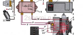
Connection diagram for generator 37.3701 for VAZ 2108, 2109, 21099 cars
Full version of the site
FakeHeader
Comments 16
My brain explodes at the end of the article! Maybe I didn’t understand correctly, but from what I read I concluded that from the generator, namely, from the brushes, we throw the wire to the relay on pin 67, and from pin 15 we throw the wire again on the generator, namely on the M8 threaded stud, where 2 thick wires. So? Did I understand everything correctly?
So, here it would be necessary to be more precise. if you have a wire from the brushes going to the diode bridge, then you need 67 from the brushes and 15 to the wire that was inserted into the brushes. if not, then the wire comes from the brushes at 67 and 15 goes to that pin. But in this and in the case that the wire is a pin, this is the + output.
In general, I have an Oda and it has a VAZ2105 type generator with a tablet in the generator on the brushes, I bought myself a generator from a VAZ 2101 and now I’m looking for information on how to connect it. I have only 2 wires coming from my original generator, one double, on the M8 stud, the other to the terminal on the generator, and now a terminal has formed from the brushes, that’s the question, that’s why I’m asking how to properly connect with an external relay. I myself am not an electrician, for me these are murky miracles))) That is, as I understand it, we loop the relay on the generator from brushes 67 and from 15 to the M8 pin, leaving everything else unchanged? I looked at the diagram in the article, where the wire from the gene goes to 67 in the relay, and from 15 to the fuse block, here I am in a stupor... firstly, where to connect in the block, and secondly, the option with a loop confused me, because . It turns out 2 different connection options.
Diagnostics
Due to the fact that the price of a new generator is “biting”, and maintainability is quite high, many motorists do it themselves with their own hands to eliminate generator malfunctions in the VAZ 2110, which I suggest you do with the help of these instructions:
Fault No. 1
In the case when the control light on the instrument panel indicates a discharge of the battery, and when checking with a tester in the electrical circuit of the car, the voltage does not rise above 13.2 volts, it is necessary to check:
- Tension of the VAZ generator drive belt - tighten if necessary;
- If the rectifier block valve is damaged, replace the entire rectifier block;
- Diodes powering the exciting winding of the rotor - replacement of diodes or the entire rectifier block;
- The outputs of the exciting winding coming from the slip rings for their unsoldering - solder the outputs/replace the rotor or the entire generator assembly.
It is also possible that the stator winding may short-circuit, break or short circuit to ground (in this case, noise from the generator appears in the VAZ 2110, the generator “howls”). These assumptions are checked using an ohmmeter; if a malfunction is detected, the stator or the entire generator must be replaced.
Malfunction No. 2
The warning lamp in the instrument panel also indicates that the battery is low, and the tester displays a voltage value in the vehicle circuit of at least 14.7 volts:
The voltage regulator has definitely failed (the contacts of the “DF” output have closed with ground) - replace the regulator.
Malfunction No. 3
The generator noise is clearly audible in the VAZ 2110:
- If sounds such as howling and squealing are heard. When disconnected, the wires remain, and when the drive belt is removed, they disappear, this means that the bearings have failed - replace the bearings (the front one is replaced as an assembly with a cover);
- If, when the wires are disconnected, the noise disappears, this indicates a short circuit in the stator windings and their connection to ground—replace the stator/generator.
Also in this case, one of the valves may close, which threatens to replace the rectifier unit.
Malfunction No. 4
The warning lights in the instrument panel do not light up when turning the ignition key:
- Checking the “F19” fuse in the mounting block - replacement (it is advisable to find out the reason for the fuse failure);
- Open circuit in the instrument cluster “ignition switch” - check the integrity of the blue wire with a red stripe running from the mounting block to the ignition switch, as well as the orange wire running from the instrument panel to the mounting block;
- Malfunction of the ignition switch contact group - check the presence of a contact with a tester, if necessary, replace the contact group or the entire ignition switch.
Principle of operation
Let's move on to the most interesting part of our article. So, turn the ignition key in the lock and:
- Electric current is supplied to the slip rings, through the brush assembly, and then to the rotor field winding;
- In the winding of the rotor, which begins to rotate simultaneously with the engine crankshaft, there is a magnetic field that penetrates the stator windings, resulting in a variable voltage at its terminals;
- When the generator reaches a certain rotation speed, it goes into self-excitation mode, that is, the current to the rotor field winding begins to flow directly from the generator itself;
- The generated alternating voltage is converted into direct voltage using a rectifier unit. It is in this state that the processes of charging the battery and providing electricity to current consumers take place;
- The voltage regulator comes into operation while the vehicle is moving, when the load on the generator and its rotation speed change. Its task is to regulate the switching time of the exciting rotor winding.
This time decreases with lower external loads and with increasing generator rotor speeds, and increases with increasing loads and decreasing rotation speeds.
Working principle of AC generator set
I hope my brevity did not prevent you from understanding the principle of operation of an alternating current generator set, otherwise you can always find a video on the topic on the Internet.
Attention! In the case when consumers in the on-board network “take” more current than the generator can produce, the required amount begins to be supplied by the battery. Advice! The vehicle's instrument panel is equipped with an indicator lamp, which informs the operation of the generator set.
Don't forget to look in her direction sometimes
Advice! The vehicle's instrument panel is equipped with an indicator lamp, which informs the operation of the generator set. Don't forget to look in her direction sometimes.
So, the main parameters are:
- Rated values of voltage, current and excitation frequency;
- The frequency with which self-excitation of the winding occurs;
- Efficiency factor (efficiency).
In our case, the electrical system has a rated voltage of 12 volts, and the rated current is the maximum amount obtained at the rated speed of the generator (80 amperes at 6000 rpm).
Checking generator operation
You can check the functionality of the generator in several ways using certain methods, for example: you can check the output current of the generator, the voltage drop on the wire that connects the current output of the generator to the battery, or check the regulated voltage.
To check, you will need a multimeter, a car battery and a lamp with soldered wires, wires for connecting between the generator and the battery, and you can also take a drill with a suitable head, since you may have to twist the rotor by the nut on the pulley.
Basic check with a light bulb and multimeter
Connection diagram: output terminal (B+) and rotor (D+). The lamp must be connected between the main output of the generator B+ and contact D+. After this, we take the power wires and connect the “minus” to the negative terminal of the battery and to the generator ground, the “plus”, respectively, to the plus of the generator and to the B+ output of the generator. We fix it on a vice and connect it.
We turn on the tester in DC mode, attach one probe to the battery to “plus”, and the second one too, but to “minus”. Next, if everything is in working order, then the light should light up, the voltage in this case will be 12.4V. Then we take a drill and start turning the generator, accordingly, the light bulb will stop burning at this moment, and the voltage will already be 14.9V. Then we add a load, take an H4 hologen lamp and hang it on the battery terminal, it should light up. Then we connect the drill in the same order and the voltage on the voltmeter will show 13.9V. In passive mode, the battery under the light bulb gives 12.2V, and when we turn it with a drill, it gives 13.9V.
Generator test circuit
Strictly not recommended:
- Check the functionality of the generator by short circuit, that is, “to spark”.
- It is also undesirable to allow the generator to operate without consumers turned on; it is also undesirable to operate with the battery disconnected.
- Connect terminal “30” (in some cases B+) to ground or terminal “67” (in some cases D+).
- Carry out welding work on the car body with the generator and battery wires connected.
Many motorists are interested in how to excite a generator without using a battery. This may be necessary for those motorists who often travel long distances, and the battery will last no more than 2 hours without recharging the car. Let's figure out how to do this.
Additional weight on the generator
Is additional mass needed for the generator? Is it always useful and how can you easily and quickly organize additional mass for your car’s generator?
In fact, now we will briefly consider these issues.
For new cars this issue is not critical, but over the years this topic has become more and more relevant. After all, over time, everything in this World tends to grow old, wear out and lose its former properties.
So it is in this case.
In fact, on most cars the generator initially does not have a direct connection with the body via line 31 (ground), but is connected to it through many intermediate connections. After all, first the generator is screwed to the bracket, the bracket to the engine
Then the whole thing goes to the starter mounting bolt. A wire tip from the negative terminal of the battery is screwed to the starter mounting bolt, which is connected to the wire itself via a crimp
This wire comes to the battery and through another crimp...
... goes to the crimped tip, which is screwed to the body
As you can see, the path is not quite simple and at each section, over time, obstacles may arise in the form of oxides, weakening of connections and crimps, which leads to a drop in voltage at the contact points and other related problems.
In the everyday life of a simple driver, this manifests itself in the form of voltage drops in the on-board network when consumers are turned on and in not entirely stable voltage in general.
On the diagnostic graphs we can see this picture, when a fairly straight line in the past turns into a saw
Therefore, the moment comes when we need to help our car. The options, of course, may be different, but the additional mass for the generator is the simplest in operation and the most budget-friendly in price.
There are also quite a few options for how to transfer additional mass to the generator and where to attach it, and everyone decides for themselves what to do. I'll just show you how I did it personally.
First of all, I bought a copper braid 40 cm long for 25 UAH
For convenience, remove the air filter housing
It is most convenient to screw the additional mass under the generator mounting nut, where the power steering tube mounting bracket is also attached. Use a 12mm wrench to unscrew the nut.
We remove the bracket, clean it, treat it with a contact protector and put on the tip of our additional ground wire
Reinstalling the bracket
and tighten the nut
Further opinions were divided. One half of the brain was in favor of a simpler solution - screw this additional wire onto the bolt securing the air conditioning tube bracket
But I didn’t want to disturb all these rubber bands once again, and the tube itself is isolated from the mass... In general, I didn’t touch this bracket and listened to the other half of my brain, which advised me to screw it to the lonely threaded hole on the spar
Having cleaned it a little and treated it with contact protector, I completed the task.
It turned out like this
Well, actually, the first results. That's how it was
Something like this
That's all. This issue can be discussed in the comments below.
I hope the information was interesting for you.
Generator device
The design of a car generator implies the presence of its own rectifier and control circuit. The generating part of the generator, using a stationary winding (stator), generates three-phase alternating current, which is then rectified by a series of six large diodes and the direct current charges the battery. Alternating current is induced by the rotating magnetic field of the winding (around the field winding or rotor). Next, the current is supplied to the electronic circuit through the brushes and slip rings.
Generator structure: 1.Nut. 2. Washer. 3.Pulley 4.Front cover. 5. Distance ring. 6.Rotor. 7.Stator. 8.Back cover. 9.Casing. 10. Gasket. 11.Protective sleeve. 12. Rectifier unit with capacitor. 13.Latch holder with voltage regulator.
The generator is located at the front of the car engine and is started using the crankshaft. The connection diagram and operating principle of a car generator are the same for any car. There are, of course, some differences, but they are usually associated with the quality of the manufactured product, the power and the layout of the components in the motor. All modern cars are equipped with alternating current generator sets, which include not only the generator itself, but also a voltage regulator. The regulator equally distributes the current in the excitation winding, and it is due to this that the power of the generator set itself fluctuates at a time when the voltage at the power output terminals remains unchanged.
The principle of operation of a car generator
Connection diagram for the VAZ 2110-2115 generator
The alternator connection diagram includes the following components:
- Battery.
- Generator.
- Fuse block.
- Ignition.
- Dashboard.
- Rectifier block and additional diodes.
The principle of operation is quite simple: when the ignition is turned on plus through the lock, the ignition goes through the fuse box, light bulb, diode bridge and goes through a resistor to minus. When the light on the dashboard lights up, then the plus goes to the generator (to the excitation winding), then during the process of starting the engine, the pulley begins to rotate, the armature also rotates, due to electromagnetic induction, electromotive force is generated and alternating current appears.
Next, the diode passes plus into the rectifier block through a sine wave into the left arm, and minus into the right arm. Additional diodes on the light bulb cut off the negatives and only positives are obtained, then it goes to the dashboard assembly, and the diode that is there allows only the negative to pass through, as a result the light goes out and the positive then goes through the resistor and goes to the negative.
The principle of operation of a car DC generator can be explained as follows: a small direct current begins to flow through the excitation winding, which is regulated by the control unit and is maintained by it at a level of slightly more than 14 V. Most generators in a car are capable of generating at least 45 amperes. The generator operates at 3000 rpm and above - if you look at the ratio of the size of the fan belts for the pulleys, it will be two or three to one in relation to the engine frequency.
To avoid this, the plates and other parts of the generator rectifier are partially or completely covered with an insulating layer. The heat sinks are combined into a monolithic design of the rectifier unit mainly by mounting plates made of insulating material, reinforced with connecting bars.
Next, let's look at the connection diagram for a car generator using the example of a VAZ-2107 car.
Design features of generators
Translated from Latin, “generation” means “birth” . Energy engineers use this name to refer to the principle of generation of electricity.
Energy is the movement of matter as it changes from one form to another:
The devices began to be called generators, where the kinetic energy of rotation is converted into electricity. Such devices can generate both direct and alternating current. The operation of the generators is based on electromagnetic induction , which supplies an electromotive force to a uniform magnetic field where a rectangular circuit or wire frame is located. When it rotates, its sides pass near the magnetic poles. In this case, the currents change directions, since near the south or north pole they are forced to take its position.
To generate direct current a special frame so that it maintains the direction with a constant voltage value. In a DC generator, the main elements include:
- External power frame with magnetic poles.
- Stator with rotating rotor.
- Brushes in the switching unit.
The generators' armatures drive the engines. Similar devices have found application in metallurgy and are used in various types of transport.
Checking for serviceability
Repair of the VAZ 2109 or VAZ 21099 generator is carried out in case of failures in the operation of the unit. There are several ways to determine generator malfunctions. The most optimal of these is diagnostics using a multimeter, but you will also need an assistant to carry it out. We will tell you further about how to check the generator on a VAZ 21099 or 2109 using a tester.
So, to determine generator faults with a multimeter, follow these steps:
- First of all, it is necessary to diagnose the VAZ voltage regulator. As practice shows, if the generator on a VAZ 2109 or VAZ 21099 does not work correctly, the problem may lie in the functionality of the three-level voltage regulator. This is especially facilitated by overvoltage in the electrical circuit. To check, you need to set the voltage measurement mode on the tester. So, start the engine and measure the voltage at the battery terminals or at the terminals of the generator unit itself. If everything is normal, then this parameter will fluctuate around 14-14.2 volts. Then press the gas and check the parameter again - it should increase, but no more than 0.5 volts. If the indicators on a VAZ 2109 carburetor or VAZ 21099 injector are different, this indicates that the element is not functioning correctly. Most likely, the VAZ 2109 voltage relay will have to be replaced.
- Next, the diode bridge of the generator is diagnosed. The bridge itself consists of six elements, three of which are considered positive and the remaining three are considered negative. Some diodes have mass at the anode, and the other part at the cathode. To check the diode bridge of the VAZ generator, the tester is switched to sound mode, that is, when the probe outputs are shorted, you can hear a characteristic sound. You are required to test each diode in different directions, and the sound should be heard in only one of them. If during testing the sound is heard in both directions, this indicates that the diode is broken. The best option would be to replace the diode bridge.
- Before disassembling the unit and repairing it, check the functionality of the stator; it is a steel cylinder, inside of which the winding of the mechanism is located. For diagnostics, you need to disconnect the stator leads from the diode bridge. First, inspect the element visually - there should be no signs of damage or burning. The multimeter is set to resistance measurement mode. First, measure the resistance parameter between the winding terminal and the housing (any terminal can be used). The obtained indicators should be high and tend to infinity. If the readings are 50 kOhm, this indicates the need to replace the generator.
- Using a multimeter, you can also check the performance of the rotor - it is a steel rod with a wound winding. At one end of the rod there are rings through which the brushes of the VAZ generator pass. You need to dismantle the rotor and visually inspect the condition of the generator winding and bearing. The integrity of the winding can be checked using a multimeter, after which the resistance parameter between the rings is measured. The results obtained should be no more than a few ohms. Replacing the VAZ 2109 generator brushes is required if they are worn out.
Node diagnostics with a tester
Basic rules when checking a generator
The basic rules used when checking the generator voltage are simple, but mandatory for all car owners without exception:
- Under no circumstances should the functionality of the generator be tested using a so-called spark, that is, using a short circuit;
- It is not allowed to connect the device to the generator terminal “+”;
- Welding work cannot be carried out in the body of the car if the wires are connected to the battery and generator.
It is important to consider the following points when checking voltage:
- measurements are carried out using special instruments called a voltmeter and an ammeter;
- checking the valves of the device is permitted if the voltage does not exceed 12 V;
- If the voltage test requires replacement of the wiring, you need to select identical wires both in cross-section and in length.
Before starting the test, make sure that all connections are working properly and that the device belt tension is correct.
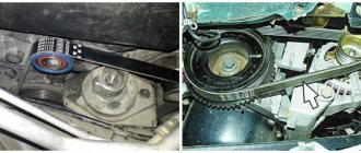
To make sure that the belt is correctly tensioned, you need to press on its middle, applying a force of 10-12 kgf. With the correct tension, the belt should bend by 12-15 mm, no more.
Technical specifications
If the old generator fails, many motorists wonder which generator they should now replace the old one with.
There is no need to invent anything here. The most correct solution is to install the same generator as before, or a more powerful one.
Today, the VAZ 2110 provides for the use of three types of power supply devices:
- Katek 5102.3771. The generator produces 80 Ampere power and its voltage is approximately 14V.
- Katek 94.3701. This is a device with the same parameters. They are not seriously different.
- Catek 120 amp. A generator that is more adapted to modern realities, when in addition to standard electrical equipment, motorists install many additional devices.
If you have a powerful audio system in your car, you use an electric pump powered by the car, as well as a number of other additional consumers, it is recommended to install a 120-amp unit instead of a standard 80-amp generator.
If we take into account the size of the devices, then we can distinguish between ordinary and compact ones. They have a certain difference in design
To be specific, the differences are in the following components:
- Brackets;
- Anchor;
- Excitation wire;
- Drive pulley;
- Number of mounting bolts.
But in reality this does not play a special role. After all, the structure of all generators used for the VAZ 2110 is the same. Therefore, let's look at the circuit and structure of this unit.
Element
Functions
He's an anchor. It is a rotating element of the generator, which creates a magnetic field due to the excitation winding located on the shaft. The field wire receives power from the slip rings. They are mounted on the same shaft. There was also room for a drive pulley, field winding wire, bearing assembly and fan impeller. There may be 1-2 last ones
This is a stationary three-phase element that includes three windings. They provide the creation of alternating current. The windings are connected to each other using a triangle or star
A lightweight non-magnetic aluminum alloy is most often used to make the generator housing. The body looks like a pair of covers connected by a bolt. The front cover is located near the drive pulley, and the rear cover is located on the side of the slip rings. Each connecting bolt must be tightened. To disassemble the housing, simply unscrew the mounting bolts.
The upper mounting bracket for the generator uses two bolts, while the lower bracket is predominantly mounted on one bolt. In some cases there are two. It is not recommended to modify the brackets, since the factory one performs important functions. The purpose of the brackets is to hold the generator. It is recommended to monitor the condition of the brackets as they are subject to wear and breakage
It consists of a pair of graphite brushes, springs that press the brushes, as well as a brush holder
Brush holder assembly and voltage wires
This design is typical for modern Katek generators. Therefore, if the regulator fails, you will have to replace the entire assembly
Equipped with 6 diodes, it is responsible for converting alternating current into direct current. It is direct current that is required for the operation of all auto equipment. This element charges the battery, among other functions.
Belt drive transmission
The belt drive allows you to increase the speed at which the crankshaft rotates. If the pulley has a small diameter, then the V-belt will wear out faster. Therefore, for small driven pulleys it is recommended to use a poly-V-ribbed drive. It is most often found in modern generators
Internal organization
The presented device is relevant for all generators used on the VAZ 2110, regardless of their power - 80-120 Amperes.
Margin of safety
If we take into account the standard Katek generator, which is installed on domestic dozens, then its resource is enough for about 10 years of operation or 140 thousand kilometers. Many fear that a powerful 120 A generator can negatively affect the condition of the battery.
In practice, nothing like this happens. Moreover, installing a more powerful unit is recommended if you plan to install an impressive audio system or video equipment on the car
Many people fear that a powerful 120 A generator can negatively affect the condition of the battery. In practice, nothing like this happens. Moreover, installing a more powerful unit is recommended if you plan to install an impressive audio system or video equipment on the car.
Quick check of the generator outside the car
Diagnostics
Due to the fact that the price of a new generator is “biting”, and maintainability is quite high, many motorists do it themselves with their own hands to eliminate generator malfunctions in the VAZ 2110, which I suggest you do with the help of these instructions:
Fault No. 1
In the case when the control light on the instrument panel indicates a discharge of the battery, and when checking with a tester in the electrical circuit of the car, the voltage does not rise above 13.2 volts, it is necessary to check:
Checking the voltage in the on-board network
- Tension of the VAZ generator drive belt - tighten if necessary;
- If the rectifier block valve is damaged, replace the entire rectifier block;
- Diodes powering the exciting winding of the rotor - replacement of diodes or the entire rectifier block;
- The outputs of the exciting winding coming from the slip rings for their unsoldering - solder the outputs/replace the rotor or the entire generator assembly.
It is also possible that the stator winding may short-circuit, break or short circuit to ground (in this case, noise from the generator appears in the VAZ 2110, the generator “howls”). These assumptions are checked using an ohmmeter; if a malfunction is detected, the stator or the entire generator must be replaced.
Malfunction No. 2
The warning lamp in the instrument panel also indicates that the battery is low, and the tester displays a voltage value in the vehicle circuit of at least 14.7 volts:
The voltage regulator has definitely failed (the contacts of the “DF” output have closed with ground) - replace the regulator.
Malfunction No. 3
The generator noise is clearly audible in the VAZ 2110:
- If sounds such as howling and squealing are heard. When disconnected, the wires remain, and when the drive belt is removed, they disappear, this means that the bearings have failed - replace the bearings (the front one is replaced as an assembly with a cover);
- If, when the wires are disconnected, the noise disappears, this indicates a short circuit in the stator windings and their connection to ground—replace the stator/generator.
Also in this case, one of the valves may close, which threatens to replace the rectifier unit.
https://youtube.com/watch?v=oK5FpoIF6i8
Malfunction No. 4
The warning lights in the instrument panel do not light up when turning the ignition key:
- Checking the “F19” fuse in the mounting block - replacement (it is advisable to find out the reason for the fuse failure);
- Open circuit in the “ignition switch” instrument cluster - check the integrity of the blue wire with a red stripe running from the mounting block to the ignition switch. as well as an orange wire running from the instrument panel to the mounting block;
- Malfunction of the ignition switch contact group - check the presence of a contact with a tester, if necessary, replace the contact group or the entire ignition switch.
Malfunction No. 5
When the ignition is turned on and the engine is running, the warning lamp indicating a low battery does not light up, the remaining lamps in the instrument cluster work:
- Burnt-out control lamp/poor contact – replace the burnt-out lamp/clean and press the contacts in the seat;
- Open circuit “generator output “D” to the instrument panel” - check for continuity of the brown wire with a white stripe coming from terminal “D” to the instrument panel;
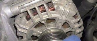
- Oxidation of contact rings, as well as hanging and wear of brushes - the brush holder assembly with brushes should be replaced, the contact rings should be wiped with a clean cloth moistened with a degreaser;
- Open circuit “DF terminal – ground” (damage to voltage regulator) – replace the regulator;
- Broken brush holder wire from terminal “D+” - restore contact;
- The positive diodes (valves) have closed - replace the rectifier unit;
- The leads coming from the slip rings to the rotor excitation winding have been unsoldered - solder the leads in place/replace the rotor/replace the generator.
This is where the list of the main malfunctions of the VAZ 2110 generator ends, I hope that this instruction will help you out at the right moment. As they say - no nail, no wand)))
The VAZ 2110 generator does not turn on
The problem is this, the car is 2008, Europanel. I decided to replace the tidy with a more recent one, because... mine started doing strange things. I found in the advertisements a dashboard from a fresh Kalina, and the price is sweet, only 1000 rubles and the mileage on it is 800 km. The owner said that when he bought the car from the showroom, he immediately ordered a Gamma (Tidy) for himself, and put this one in. Here you go. I take this tidy for myself by giving 1000 rubles. I plug it in and what do I see? I don’t have a charger, the battery on the panel is on, I accelerated to 2500 thousand, charging started, the light went out. I installed my old device and there is no such thing. What could this be? I want a new device and I want it to charge?
Auto-Translated Original (RU)
How to check the generator excitation wire
Rule 1: If your dashboard light with the battery icon lights up or starts to burn dimly (of course, only when the engine is running), take action immediately.
If you don't do this, you may stall in the most unexpected place. In addition, operating the generator when it has malfunctions can worsen the situation. Rule 2: If you do not feel competent in this area, you do not have the necessary tools and spare parts, do not try to repair the generator yourself. Rule 3: Do not check for charging by disconnecting the battery while the engine is running. This is a harmful activity, and this method can damage both the generator and the injection control unit and other electronic components. Rule 4 Do not trust other people's advice in repairs. Advice like “change this or that’s what happened to me” can do a lot of harm.
Before changing everything, it is better to properly check all the parts and replace only the necessary ones. Rule 5: if done, do it well, using decent spare parts and replacing all non-conforming parts. Rule 6: Before dealing with an undercharged battery or low on-board voltage, carefully check the mass of the generator. Option 1 The charging lamp (also known as excitation lamp, also known as charging indicator) does not light up either when the ignition is turned on or when the engine is running.
Possible reasons - the lamp burned out, the excitation wire is not connected to the generator (broken, there is no contact in the connector, it was simply disconnected), there is no power to the dashboard, the brushes are completely out of order, the armature is out of order, the voltage regulator is out of order (other reasons) . Check with the ignition on, check for the presence of supply voltage (= battery voltage or slightly lower) on the excitation wire disconnected from the generator (usually a thin wire, blue with a white stripe, cross-section 0.75 - 1.0) relative to ground. If there is, you can additionally verify the operability of the entire circuit by connecting the excitation wire to ground (the lamp will light up), of course, only by disconnecting this wire from the generator; if during such a check, using the generator body as a ground, you can check for the presence of one on the generator.
If all these checks have confirmed the operability of the corresponding elements, check the generator (remove, disassemble, check). Option 2 The charging lamp lights up when the ignition is on, after starting it does not go out and does not respond to an increase in speed. The only hope of avoiding disassembling the generator is a torn belt or a belt brought to the last stage of abrasion or weakened almost completely.
It is extremely unlikely that the bare wire will touch the excitation mass. Option 3, the lamp lights up, goes out after starting, then starts to burn barely (especially noticeable at night) brighter as the load increases. Most likely the reason lies in the generator in the brush assembly. A possible cause is the belt.
Option 4, the lamp lights up, goes out when starting (or does not go out), then starts to burn either brighter or weaker, depending on the speed and load, it can go out spontaneously (forever). Remove and check the generator. It is extremely unlikely that the field wire will touch ground. Option 5, the lamp behaves absolutely normally, nothing foretells trouble, however, the battery is constantly discharged, and when driving at night, you may encounter a situation where, with numerous consumers turned on, the car suddenly stalls and it is impossible to start it because the battery is completely discharged. This case is very common but does not always manifest itself so clearly.
The essence of the matter is that the generator provides charging, but if sufficiently large loads are connected, the charging voltage drops, sometimes very significantly, and as a result the battery is constantly undercharged. If such phenomena are detected, it is necessary to carry out the following check before checking the generator. Checking the charging voltage. Often, the so-called masters check the presence of charging in an exclusively wild way, in my opinion - by removing the terminal from the battery while the engine is running. The method is unacceptable and completely uninformative.
Those who understand something use a tester or a multimeter or even a separate voltmeter. At the same time, verifiers very often make a number of the same standard mistakes: 1 the presence of an increase in voltage after starting at the battery terminals is considered sufficient and no further checks are made. 2 Having determined the voltage on the battery, the inspector is not always aware of its compliance with the standards for a given generator. 3 the presence of a voltage less than the norm is perceived as an absolute defect of the generator. 4 load tests are not performed.
How to check. 1) start the engine and use a digital multimeter to check the voltage at the battery terminals (consumers are disconnected, idling). 2) check compliance with the specifications for this generator. In general, the norm can be considered a voltage above 13.8 - 13.9 Volts and below 15 Volts for modern generators or 14.
5 for generators older than 10 years (approx.). 3) if the voltage is normal, check by connecting the maximum number of consumers (headlights, heated rear window, heater fan). A voltage drop of no more than 0.5 Volts can be considered normal, even if to ensure this condition it is necessary to increase the speed to 1300-1500. 4) check for voltage increase with increasing rpm (should not exceed 15 Volts or as per specific specification).
5) if initially the voltage on the battery is below normal, check what voltage is directly on the generator. The difference in voltage on the battery and on the terminals of the generator itself should not be more than 0.1 Volt without loads and more than 0.3 Volts in the presence of the most powerful consumers. If the difference goes beyond this range, it is necessary to calculate the voltage drop point. To do this, you need to measure the voltage drop directly in the generator ground circuit and in the positive circuit. It is necessary to measure the voltage between the positive terminal on the generator and the battery terminal and between the generator housing and the negative terminal of the battery.
It is necessary to take into account that, depending on various factors, there can be many points where the voltage drop occurs. After detecting a voltage drop in a circuit, such as a mass, the drop point is calculated as follows: 5. 1 you need to turn on all the loads and measure the drop. Assuming a drop of 1 Volt, then from a starting point, for example the generator housing, you need to reduce the number of chain links and observe the change in the value of the voltage drop. The mass circuit consists of the following elements: 5. 1.
Device
Before you look for alternator faults in your VAZ 2110, you need to know that the fundamental design and principle of its operation are the same for all types of cars. They can differ only in dimensions, workmanship and location of mounting fasteners. Therefore, to broaden your horizons, you can listen to the advice of owners of all brands of cars, since some generator spare parts are interchangeable.
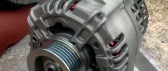
The photo highlights the main components of the generator:
- Alternator belt pulley (I hope there is no need to explain its purpose);
- A housing consisting of a front half located on the pulley side and a rear half, which is installed on the slip ring side. In addition, in the rear part of the case there is a brush assembly, a rectifier, a voltage regulator, as well as electrical wiring leads for connecting to the vehicle's electrical circuit.
The stator is installed in the housing, and the rotor support bearings are placed; it also has fastenings for installing the generator on the car engine.
- A rotor with excitation windings, the terminals of which are connected to cylindrical slip rings made of copper;
- The heart of the generator is the stator. It is in the grooves between its steel sheets where the three-phase winding is located and the electric current necessary for the car is generated;
- Assembly of rectifier diodes (no comments);
- A voltage regulator is necessary to maintain the voltage in the vehicle's electrical circuit within the specified parameters during changes in loads, generator speed and ambient temperature;
- Brush assembly, where there are spring-loaded brushes in contact with the rotor slip rings;
- Plastic cover protecting the diode module.
How to excite a gene
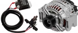
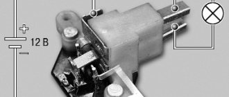
So, what needs to be done to excite the generator? As mentioned above, the tablet should be removed from the generator, since the malfunction arose precisely there. Next, connect the positive terminals of both devices, and cut the negative terminal in the chocolate bar. During the assembly process, connect it to a mass of brushes.
Insulate the wire from terminal “30” of the gene, connect an indicator with a power of no more than 15 W to the output circuit “15”. This applies to the genes of the G222 series. If the units are of other models, then they must be excited by connecting the indicator to terminal “B”.
Self-excitation of a generator can be imagined this way.
In the diagram above, the leftmost arrows indicate diodes. They are installed only in generators of modern models; they do not exist in older units. More precisely, the circuit without the presented diodes is considered classic, and with them - modernized, modern.
In some gene models, the anchors imply the presence of brushes. They are also removed and the tablet is drilled out. One contact goes directly to the armature through the diodes to the plus, as can be seen in the diagram, the second contact goes to the minus (lowest arrow).
Connection diagram for the VAZ-2101 generator
Structurally, generator 2101 consists of the following main elements:
- The rotor is a moving part that rotates from the engine crankshaft. Has an excitation winding.
- The stator is the stationary part of the generator and also has a winding.
- Front and back covers, inside of which bearings are installed. They have eyelets for attaching to the internal combustion engine. The back cover contains a capacitor necessary to cut off the alternating current component.
- Semiconductor bridge - called a “horseshoe” for its similarity. Three pairs of semiconductor power diodes are mounted on a horseshoe-shaped base.
- A pulley on which the VAZ-2101 generator belt is put. The belt is V-shaped (on modern cars a multi-ribbed belt is used).
- The voltage regulator is installed in the engine compartment, away from the generator. But still it must be considered part of the structure.
- The brushes are mounted inside the generator and transmit the supply voltage to the field winding (on the rotor).
Car generator circuit
The most basic function of the generator is to charge the battery and power the electrical equipment of the engine.
A generator is a mechanism that converts mechanical energy into electrical energy. The generator has a shaft on which a pulley is mounted, through which it receives rotation from the engine crankshaft.
Interactive image of the generator circuit. Works on mouseover
A car generator is used to power electrical consumers, such as the ignition system, on-board computer, car lighting, diagnostic system, and it is also possible to charge a car battery. The power of a passenger car generator is approximately 1 kW. Car generators are quite reliable in operation because they ensure uninterrupted operation of many devices in the car, and therefore the requirements for them are appropriate.
