A Ground B L-line of engine diagnostics (including the line for reading slow self-diagnosis codes), ABS (8192-Baud Serial Data) (not always wired) C AIR (not always wired) D SES-Lamp - self-diagnosis lamp line (not always wired) E K diagnostic line (160-Baud Serial Data) F TCC (not always wired). On some models - +12V power supply G Fuel pump control (not always wired) J K-line for airbag diagnostics (AirBag) (8192-Baud Serial Data) M K-line for engine diagnostics, ABS
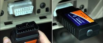
16-pin trapezoidal OBD-II connector (lada Obd-2 16-pin)
2) J1850 Bus+ 4) Body ground 5) Signal ground 6) CAN-High line, J-2284 7) K-line diagnostics (ISO 9141-2 and ISO/DIS 14230-4) 10) J1850 Bus- 14) Line CAN-Low, J-2284 15) L-line diagnostics (ISO 9141-2 and ISO/DIS 14230-4) 16) +12V power supply from battery
The pinout of the OBD 2 connector will allow the car owner to correctly connect the contacts of the block for vehicle diagnostics. A scanner or personal computer (PC) is connected to this plug to check the car.
Description and features of OBD 2
Where is OBD 2 located?
OBD 2 pinout
Diagnostics via OBD 2
Video “How to diagnose a car using OBD 2?”
Comments and Reviews
Description and features of OBD 2
The standard OBD 2 vehicle diagnostic system includes the X1234 code structure.
Each character here has its own meaning:
- X - the element is the only letter and allows you to find out the type of car malfunction. The power unit, transmission, sensors, controllers, electronic modules, etc. may not work correctly.
- 1 - general OBD class code. Depending on the car, it is sometimes an additional manufacturer code.
- 2 - using the symbol, the car owner will be able to clarify the location of the problem. For example, this could be the ignition system, battery power (rechargeable battery), additional power lines, etc.
- 3 and 4 - determine the serial number of the malfunction.
The main feature of the block is the presence of a power output from the vehicle's electrical network, which makes it possible to use scanners that do not have built-in power lines. Initially, diagnostic protocols were used to obtain data about the occurrence of problems in the operation of systems. Pads in modern cars allow consumers to receive more information about errors. This is ensured by the connection of diagnostic scanners and devices with electronic modules in the car.
Depending on the adapter manufacturer, the device may belong, for example, to the following international classes:
The World of Matizov channel spoke in detail about the purpose of diagnostic pads and their use.
Connection via adapters
p, blockquote 28,0,0,0,0 —>
If a non-standard connector is installed on your car (cars manufactured before 2000, or trucks or commercial vehicles), you can use special adapters or make them yourself.
p, blockquote 29,0,0,0,0 —>
On the Internet you can find a diagram for reconnecting connector pins similar to that shown in the figure:
p, blockquote 30,0,0,0,0 —>
p, blockquote 31,0,0,0,0 —>
If the car is in constant use or for professional work as an auto electrician, it is easier to purchase an adapter (adapter set).
p, blockquote 32,0,0,0,0 —>
For the AUTOCOM diagnostic scanner they look like:
p, blockquote 33,0,0,0,0 —>
p, blockquote 34,0,0,0,0 —>
The minimum standard set for passenger cars includes eight adapters. One connector of the adapter is connected to the OBD connector of the car, the other to the OBD diagnostic cable or directly to the BLUETOOTH ELM 327 scanner.
p, blockquote 35,0,0,0,0 —>
The use of adapters does not provide vehicle diagnostics in all cases. Some cars do not support OBD pairing even though they can be connected to the OBD connector. This applies more to older cars.
Where is OBD 2 located?
The different positions of the diagnostic plug in a car are due to the fact that vehicle manufacturers do not use a single standard regarding the installation of pads. If the device is classified as J1962, it must be installed within a radius of 18 cm from the steering column. Manufacturers actually do not follow this rule.
The device location may be as follows:
- In a special slot in the lower casing of the instrument cluster. It can be seen in the center console in the driver's left knee area.
- Under the ashtray, which is usually located in the center of the console and instrument cluster. In this place, the connector is often installed by French car manufacturers - Peugeot, Citroen, Renault.
- Under the plastic plugs located on the bottom of the instrument cluster. In this place, the pads are usually installed by the VAG manufacturer - Audi, Volkswagen, etc. cars.
- On the rear of the center console, in the area where the glove compartment housing is installed. This location is typical for some VAZ cars.
- In the area of the handbrake handle, under the plastic of the center console. This situation is typical for Opel cars.
- At the bottom of the armrest niche.
- In the engine compartment, next to the engine shield. This is where the connector is installed by Korean and Japanese manufacturers.
Lock replacement and repair
If, when you try to turn on the key, nothing happens in the lock, that is, the engine does not start, the problem may lie in a poor connection of the contacts. You can try to repair such a lock, but if this does not help, then the device will have to be changed (the author of the video is Sergey Vishnyakov).
Replacing the contact group
This task is performed as follows:
- First you need to disconnect the battery, to do this, remove the negative terminal from it. Next, the protective lining of the steering column is dismantled. Using a flat head screwdriver, you will need to remove the two bolts that secure this shroud.
- Having done this, you can dismantle the upper part of the lining.
- Next, the steering column is moved to its highest position. You will need to slightly tilt the top of the cover towards you until the fastenings of this part of the casing come out of the slot.
- Then the lining is dismantled; it must be moved upward.
- Using a flat-head screwdriver, you will need to unscrew the two bolts that secure the contact part of the lock. Then the contact component is removed and replaced with a new one, further assembly is carried out in the reverse order.
Types of connectors
In modern vehicles, two types of diagnostic sockets can be used - classes A or B. Both connectors are equipped with 16-pin outputs, eight contacts in each row. The contact elements are numbered from left to right, respectively, components numbered 1–8 are located at the top, and 9–16 at the bottom. The outer part of the body of the diagnostic block is made in the form of a trapezoid and is characterized by rounded shapes, which makes it possible to connect an adapter.
The main difference between the different types of connectors is the guide grooves located in the center.
Necessary tools, materials and programs for diagnostics
So, what you will need to prepare for a proper vehicle check:
- Diagnostic adapter with cord. When purchasing a device, you need to be sure to select the adapter that will fit your connector, so find out exactly what connector your car uses.
- Diagnostic device. We will describe an example of testing with a laptop. If you don’t have one, you can use a desktop computer, but this is extremely inconvenient, especially since you will need a household outlet to connect it. The best option is a netbook. It can work autonomously, while its dimensions are very convenient for diagnostics.
- Software for checking. In this case, you have a huge choice - you can easily find the necessary diagnostic software on the Internet, there are many options. At the same time, programs have their own characteristics and characteristics. You can give preference to free software - most of these programs are just as effective at finding errors as their paid counterparts.
Photo gallery “Getting ready for diagnostics”
OBD 2 pinout
Connection diagram of contact elements to the diagnostic block:
- Backup contact. Depending on the manufacturer, any signal can be output to it. He is appointed by the car developer.
- Pin K. Used to send various parameters to the control unit. In many cars it is designated as the J1850 tire.
- A backup contact assigned by the vehicle manufacturer.
- "Ground" of the diagnostic block connected to the vehicle body.
- Ground of the diagnostic adapter signal.
- Contact element for direct connection of the J2284 digital CAN interface.
- Contact for connecting channel K in accordance with the international standard ISO 9141-2.
- Reserve contact element, assigned by the vehicle manufacturer.
- Spare contact.
- Pin required for connection to J1850 class bus.
- The purpose of this contact is determined by the machine manufacturer.
- Appointed by the car developer.
- Reserve pin assigned by the manufacturer.
- Additional contact element for connecting the digital CAN interface J2284.
- Pin for channel L, designed for connection in accordance with ISO 9141-2 standard.
- A positive contact for connecting the car's electrical system voltage, rated for 12 volts.
As an example of a factory pinout of a block, you can use the Hyundai Sonata. In these models, the first pin of the connector is designed to receive signals from the anti-lock braking system control module. Pin number 13 is used to read impulses from the ECU (electronic control unit), as well as airbag controllers.
Pinout types may vary depending on the protocol class:
- If the car uses the ISO9141-2 standard, then this protocol is activated by using pin 7. Pins numbered two and ten are not used and are inactive. To send information, contact elements 4, 5, 7 and 16 are used. Depending on the car, contact 15 can be used for this task.
- If the car implements the SAE J1850 type VPW protocol, then the second, fourth, fifth and sixteenth pins are used in the connector. General Motors vehicles of European and American production are usually equipped with such pads.
- It is possible to use the J1850 protocol in PWM mode. This application involves the additional use of the tenth pin. A similar type of connector is installed on Ford cars. Regardless of the type of output, the seventh pin is not used.
Mikas ECU pinout
Mikas is a comprehensive car engine control system. Similar to the January system. The system includes: a set of sensors (input periphery), an electronic control unit (ECU), a set of actuators (output periphery) and a wiring harness with connectors (performs the functions of a simple interface)*. The system can use components of both domestic production and Bosch. There are 5 main modifications in total: 5.4, 7.1, 10.3, 11 and 12.3 versions.
Car engine diagnostics begins with reading error codes from the controller's RAM. Checking the wiring is quite simple if you have a Mikas pinout (pin assignment) of the controller connector and a multimeter. As a last resort, you can use a control llama, but this is not entirely convenient. Next comes the pinout of the connectors of this ECU of various modifications:
Diagnostics via OBD 2
The verification procedure is carried out as follows:
- Depending on the vehicle, the diagnostic process can be carried out with the ignition off or on. This point should be clarified in the service manual. Before starting, the ignition procedure in the car is turned off or on.
- The program is launched on the computer to check.
- The diagnostic equipment is connected to the connector. If this is a scanner, then the block with the wire from it needs to be inserted into the plug. When using a PC, one end of the adapter is installed in the USB output of the computer, and the other is connected to the connector.
- You need to wait until the program detects the block after synchronization. If this does not happen, you should manually go to the control menu and select the option to search for new devices.
- The diagnostic procedure starts on the computer. Depending on the software, the user may have the option to select the desired verification tool. Some programs support separate diagnostics of the engine, transmission unit, electrical network and other components.
- After completing the test procedure, fault codes will appear on the PC screen. These errors must be deciphered in order to accurately determine the type of failure. In accordance with the data received, the vehicle is repaired.
Car diagnostic algorithm
So, if all the settings are completed, you can begin the actual diagnostics. The first task is to connect the auto scanner to the on-board computer. Everything is simple here: we use the supplied OBD cable, which is connected to the diagnostic connector of the ECU. If the green LED on the scanner lights up, everything is in order; if not, you should look for the reason for the failure of +12V power supply to the input of the power adapter (the 16th pin of the diagnostic connector is responsible for this). Perhaps the whole point is a blown fuse protecting this section of the circuit; if it is intact, perhaps there is an open circuit or a short circuit that needs to be eliminated. For a standalone scanner, you do not need to take any additional steps. But when using the most common adapter in our country, the ELM327 family or analogues, you will need to connect it to a smartphone, laptop or any other device with a display (we already know how to set up an OBD2 adapter for Android devices or a laptop running Windows OS). After connecting via a wireless connection (advanced scanners may also have a LAN port), we launch the diagnostic program on the computer. The list of such software is quite extensive (see the article on choosing an auto scanner).
The first thing you need to do is indicate the make/model of the car, year of manufacture and engine type. After turning on the ignition, the self-diagnosis mode will start (this will be indicated by flashing LED lights on the instrument panel), after which the static fault detection mode will start. The diagnostic process should be accompanied by blinking LEDs on the scanner. At the end of the process, the program will request the codes of detected errors from the ECU and display them on the screen in a readable form. If the utility is Russified, the messages will be in Russian, but Chinese manufacturers often suffer from inaccurate translations, so it is advisable to also write down the digital error code, which should subsequently be analyzed and tried to eliminate the problem.
Most auto scanners have a mode for erasing errors from the on-board computer's memory; this option should be used after each scan. Turn off the ignition and after a few minutes start the engine, let it run for 5 - 8 minutes, after which we carry out a short drive, accompanied by all possible maneuvers (turns in both directions, braking/accelerating, reverse movement, turning on all lights and, if possible, other electrical equipment). After the test run, we turn on the diagnostic mode again and compare the results with the previous ones. Those errors that remain are active, requiring a response from the car owner. Almost all car scanners, in addition to detecting faults, allow you to observe the operation of the monitored systems in dynamics while the engine is running. The parameters of their operation are displayed on the display in the form of symbolic-numeric or graphic information, the interpretation of which requires certain skills and experience - usually this is the prerogative of professional motorists or auto electricians.
Video “How to diagnose a car using OBD 2?”
The SUPER ALI channel showed the process of testing vehicle systems using a special scanner connected to the OBD 2 connector.
With the advent of microprocessor-controlled electronic systems in cars, it became necessary to check the operating parameters of the units themselves and the connecting electrical circuits. For this purpose, they began to use diagnostics using equipment called OBD (On Board Diagnostic). Knowing the location and standard pinout of OBD 2, you can check the car yourself.
Where is OBD 2 located?
Description of connector types
OBD 2 pinout
Video “Diagnostics using ELM327”
Comments and Reviews
OBD2 adapter
Every car must be equipped with an OBD2 diagnostic adapter.
It is convenient to use for:
- car system diagnostics;
- error identification and analysis;
- monitoring the operation of the power unit;
- control voltage, speed, mileage, temperature;
- to track fuel consumption;
- monitoring the status of panel instruments;
- mileage tracking, etc.
OBD-2 adapter for scanning
When choosing a scanner, you should focus on its capabilities. Expensive devices provide more accurate diagnostics. If it is impossible to buy an expensive scanner, you should choose a scanning device made for a given car brand.
The OBD2 connector is used to connect the scanner to the ECU. Using the pinout, the scanner is connected to the vehicle's power supply and grounding, which ensures its uninterrupted operation. Thanks to OBDII protocols, parameters that affect air purity are monitored. This is environmental protection.
The presence of an OBD2 connector allows you to monitor the health of the car on your own, without resorting to expensive diagnostics.
Loading …
OBD 2 Review
OBD 2 is a vehicle diagnostic device that first appeared in the United States in 1996. In Europe, this standard has been adopted as mandatory since 2001. Thanks to its widespread implementation, errors on machines of different brands have the same appearance.
The standard code contains the X1234 structure, where each character carries its own meaning:
- X is the only letter symbol that allows you to recognize the faulty system (engine, gearbox, electronic components, etc.);
- 1 - represents the general OBD standard code or additional factory codes;
- 2 - clarification of the location of the malfunction (power or ignition system, auxiliary circuits, etc.);
- 34 is the serial number of the error.
A special feature of the connector is the presence of a power plug from the on-board network, which allows the use of scanners without built-in or additional electrical circuits. The first diagnostic protocols provided only information about the presence of a problem. Modern connectors allow you to obtain more data about a malfunction by connecting diagnostic equipment with electronic units in the car.
Each device must comply with one of three international standards:
The video from the channel Sanek Zhelezniy Kaput presents a video demonstrating testing of the SsangYong New Actyon car through the OBD 2 connector.
List of OBD Error Codes
P0 1XX FUEL AND AIR METERING Fuel and air meters PO 100 MAF or VAF CIRCUIT MALFUNCTION Air flow sensor circuit malfunction PO 101 MAF or VAF CIRCUIT RANGE/PERF PROBLEM Signal out of range PO 102 MAF or VAF CIRCUIT LOW INPUT Low output signal PO 103 MAF or VAF CIRCUIT HIGH INPUT High output signal level PO 105 MAP/BARO CIRCUIT MALFUNCTION Air pressure sensor malfunction PO 106 MAP/BARO CIRCUIT RANGE/PERF PROBLEM Signal out of range PO 107 MAP/BARO CIRCUIT LOW INPUT Low output signal PO 108 MAP/BARO CIRCUIT HIGH INPUT High output signal level PO 110 IAT CIRCUIT MALFUNCTION Intake air temperature sensor malfunction PO 111 IAT RANGE/PERF PROBLEM Signal out of range PO 112 IAT CIRCUIT LOW INPUT Low output signal level PO 113 IAT CIRCUIT HIGH INPUT High output signal level PO 115 ECT CIRCUIT MALFUNCTION Malfunction of the coolant temperature sensor PO 116 ECT RANGE/PERF PROBLEM Signal out of the permissible range PO 117 ECT CIRCUIT LOW INPUT Low output signal level PO 118 ECT CIRCUIT HIGH INPUT High output signal level PO 120 TPS SENSOR A CIRCUIT MALFUNCTION Malfunction of the throttle position sensor PO 121 TPS SENSOR A RANGE/PERF PROBLEM Signal out of range PO 122 TPS SENS A CIRCUIT LOW INPUT Low output level PO 123 TPS SENS A CIRCUIT HIGH INPUT High output level PO 125 LOW ECT FOR CLOSED LOOP FUEL CONTROL Low coolant temperature.
for closed loop control PO 130 02 SENSOR B1 S1 MALFUNCTION O2 sensor B1 S1 is faulty (Bank 1) PO 131 02 SENSOR B1 S1 LOW VOLTAGE O2 sensor B1 S1 has a low signal level PO 132 02 SENSOR B1 S1 HIGH VOLTAGE O2 sensor B1 S1 has a high signal level PO 133 02 SENSOR B1 S1 SLOW RESPONSE O2 sensor B1 S1 has a slow response to rich/lean PO 134 02 SENSOR B1 S1 CIRCUIT INACTIVE O2 sensor B1 S1 circuit is passive PO 135 02 SENSOR B1 S1 HEATER MALFUNCTION O2 sensor heater B1 S1 faulty PO 136 02 SENSOR B1 S2 MALFUNCTION O2 sensor B1 S2 is faulty PO 137 02 SENSOR B1 S2 LOW VOLTAGE O2 sensor B1 S2 has a low signal level PO 138 02 SENSOR B1 S2 HIGH VOLTAGE O2 sensor B1 S2 has a high signal level PO 139 02 SENSOR B1 S2 SLOW RESPONSE O2 sensor B1 S2 has a slow response to rich/lean conditions PO 140 02 SENSOR B1 S2 CIRCUIT INACTIVE O2 sensor B1 S2 circuit is passive PO 141 02 SENSOR B1 S2 HEATER MALFUNCTION O2 sensor heater B1 S2 is faulty PO 142 02 SENSOR B1 S3 MALFUNCTION TION Sensor O2 B1 S3 is faulty PO 143 02 SENSOR B1 S3 LOW VOLTAGE O2 sensor B1 S3 has a low signal level PO 144 02 SENSOR B1 S3 HIGH VOLTAGE O2 sensor B1 S3 has a high signal level PO 145 02 SENSOR B1 S3 SLOW RESPONSE O2 sensor B1 S3 has a slow rich/lean response PO 146 02 SENSOR B1 S3 CIRCUIT INACTIVE O2 sensor B1 S3 circuit is passive PO 147 02 SENSOR B1 S3 HEATER MALFUNCTION O2 sensor heater B1 S3 is faulty PO 150 02 SENSOR B2 S1 CIRCUIT MALFUNCTION O2 sensor B2 S1 is faulty (Bank 2) P.O. 151 02 SENSOR B2 S1 CKT LOW VOLTAGE O2 sensor B2 S1 has a low signal level PO 152 02 SENSOR B2 S1 CKT HIGH VOLTAGE O2 sensor B2 S1 has a high signal level PO 153 02 SENSOR B2 S1 CKT SLOW RESPONSE O2 sensor B2 S1 has a slow response to rich/lean PO 154 02 SENSOR B2 S1 CIRCUIT INACTIVE O2 sensor B2 S1 circuit passive PO 155 02 SENSOR B2 S1 HTR CKT MALFUNCTION O2 sensor B2 S1 heater faulty PO 156 02 SENSOR B2 S2 CIRCUIT MALFUNCTION O2 sensor B2 S2 faulty PO 1 57 02 SENSOR B2 S2 CKT LOW VOLTAGE O2 sensor B2 S2 has a low signal level PO 158 02 SENSOR B2 S2 CKT HIGH VOLTAGE O2 sensor B2 S2 has a high signal level PO 159 02 SENSOR B2 S2 CKT SLOW RESPONSE O2 sensor B2 S2 has a slow response to rich/lean PO 160 02 SENSOR B2 S2 CIRCUIT INACTIVE O2 sensor circuit B2 S2 is passive PO 161 02 SENSOR B2 S2 HTR CKT MALFUNCTION O2 sensor heater B2 S2 is faulty PO 162 02 SENSOR B2 S3 CIRCUIT MALFUNCTION O2 sensor B2 S3 is faulty PO 163 02 SENSOR B2 S3 CKT LOW VOLTAGE O2 sensor B2 S3 has a low signal level PO 164 02 SENSOR B2 S3 CKT HIGH VOLTAGE O2 sensor B2 S3 has a high signal level PO 165 02 SENSOR B2 S3 CKT SLOW RESPONSE O2 sensor B2 S3 has a slow response to rich/lean PO 166 02 SENSOR B2 S3 CIRCUIT INACTIVE O2 sensor circuit B2 S3 passive PO 167 02 SENSOR B2 S3 HTR CKT MALFUNCTION O2 sensor heater B2 S3 is faulty PO 170 BANK 1 FUEL TRIM MALFUNCTION Fuel leak from the fuel system of block No. 1 PO 171 BANK 1 SYSTEM TOO LEAN Cylinder block No. 1 lean (possibly air leakage) PO 172 BANK 1 SYSTEM TOO RICH Cylinder block No. 1 rich (possibly incomplete closing of the injector) PO 173 BANK 2 FUEL TRIM MALFUNCTION Fuel leak from the fuel system of block No. 2 PO 174 BANK 2 SYSTEM TOO LEAN Cylinder block No. 2 lean (possibly air leakage) PO 175 BANK 2 SYSTEM TOO RICH Cylinder block No. 2 rich (possibly incomplete closing of the injector) PO 176 FUEL COMPOSITION SENSOR MALFUNCTION CHx emission sensor is faulty PO 177 FUEL COMPOSITION SENS CKT RANGE/PERF Sensor signal is out of the permissible range PO 178 FUEL COMPOSITION LOW INPUT Low signal level of the СНх sensor PO 179 FUEL COMPOSITION HIGH INPUT High signal level of the СНх sensor PO 180 FUEL TEMP SENSOR A CIRCUIT MALFUNCTION Fuel temperature sensor circuit "A" is faulty PO 181 FUEL TEMP SENSOR A CIRCUIT RANGE/PERF Sensor signal " A" is out of the permissible range PO 182 FUEL TEMP SENSOR A LOW INPUT Low signal of the fuel temperature sensor "A" PO 183 FUEL TEMP SENSOR A HIGH INPUT High signal of the fuel temperature sensor "A" PO 185 FUEL TEMP SENSOR B CIRCUIT MALFUNCTION Fuel temperature sensor circuit “B” is faulty PO 186 FUEL TEMP SENSOR RANGE/PERF The signal from sensor “B” is out of the permissible range PO 187 FUEL TEMP SENSOR B LOW INPUT Low signal from fuel temperature sensor “B” PO 188 FUEL TEMP SENSOR B HIGH INPUT High signal from fuel temperature sensor “B” PO 190 FUEL RAIL PRESSURE CIRCUIT MALFUNCTION The fuel pressure sensor circuit in the fuel rail is faulty PO 191 FUEL RAIL CIRCUIT RANGE/PERF The sensor signal is out of the permissible range PO 192 FUEL RAIL PRESSURE LOW INPUT The fuel pressure sensor signal is low PO 193 FUEL RAIL PRESSURE HIGH INPUT Fuel pressure sensor signal high PO 194 FUEL RAIL PRESSURE CKT INTERMITTENT Fuel pressure sensor signal is intermittent PO 195 ENGINE OIL TEMP SENSOR MALFUNCTION Engine oil temperature sensor circuit is faulty PO 196 ENGINE OIL TEMP SENSOR RANGE/PERF Sensor signal is out of range PO 197 ENGINE OIL TEMP SENSOR LOW Oil temperature sensor signal is low PO 198 ENGINE OIL TEMP SENSOR HIGH Oil temperature sensor signal is high PO 199 ENGINE OIL TEMP SENSOR INTERMITTENT Oil temperature sensor signal is intermittent PO 2XX FUEL AND AIR METERING PO 200 INJECTOR CIRCUIT MALFUNCTION Injector control circuit is faulty Other codes malfunctions
Description of connector types
In the early 2000s, there were no strict requirements for the outer shape of the connector, and many automakers assigned the device configuration themselves. Today, there are two types of OBD 2 connector, designated Type A and Type B. Both plugs have a 16-pin output (two rows of eight pins) and differ only in the central guide grooves.
The pins in the block are numbered from left to right, with contacts numbered 1-8 in the top row, and numbers 9 through 16 in the bottom row. The outer part of the housing is made in the shape of a trapezoid with rounded corners, which ensures reliable connection of the diagnostic adapter. The photo below shows both device options.
Connector types - Type A on the left and Type B on the right
A few words about diagnostics with a laptop
The car has a diagnostic connector in the engine compartment for connecting a special motor tester. It is not economically profitable for owners to buy one because of its cost, since such checks are not carried out very often. Having at your disposal a laptop, as well as a self-made or purchased adapter. It is an adapter between the motor and the computer, and is usually supplied with a software installation disk. Having it all.
You can successfully check the condition of the power unit not only of your car, but also of your colleagues in the garage. The adapter is connected to the laptops and all systems are checked.
OBD 2 pinout
The layout and purpose of the contacts in the OBD 2 connector are determined by the standard.
Numbering of plugs in the connector
General description of plugs:
- 1 - reserve, this pin can output any signal that the car manufacturer sets;
- 2 - channel “K” for transmitting various parameters (can be designated as J1850 bus);
- 3 - similar to the first;
- 4 — grounding of the connector to the car body;
- 5 — diagnostic adapter signal grounding;
- 6 - direct connection of the CAN bus contact J2284;
- 7 — channel “K” according to ISO 9141-2 standard;
- 8 - similar to contacts 1 and 3;
- 9 - similar to contacts 1 and 3;
- 10 — pin for connecting the J1850 standard bus;
- 11 — pin assignment is set by the vehicle manufacturer;
- 12 - similar;
- 13 - similar;
- 14 - additional pin of CAN bus J2284;
- 15 — channel “L” according to ISO 9141-2 standard;
- 16 - positive output of the on-board network voltage (12 Volts).
An example of a factory OBD 2 pinout is the Hyundai Sonata, where pin 1 receives a signal from the anti-lock braking system control unit, and pin 13 receives a signal from the control unit and airbag sensors.
Depending on the operating protocol, the following pinout options are possible:
- When using the standard ISO 9141-2 protocol, it is activated via pin 7, while pins 2 and 10 in the connector are inactive. For data transmission, pins numbered 4, 5, 7 and 16 are used (sometimes pin number 15 can be used).
- With a protocol type SAE J1850 in the VPW version (Variable Pulse W >
Obd2 connector pinout - diagnostic connector pinout
Obd2 connector pinout - diagnostic connector diagram
Obd2 connector pinout - all cars produced in recent years are equipped with all kinds of electronic devices. One of the important devices is considered to be a system for performing diagnostics of equipment installed in a car. The design of this device includes an OBD2 connector that was designed in the nineties. Its main purpose is the ability to connect a scanner. In addition, it can be used to measure on-board voltage, temperature component, speed, and other parameters. Moreover, all this can be done directly while operating the vehicle.
As a rule, the obd2 connector socket is installed in the car near the steering column (the distance is approximately 180 mm). The parametric characteristics of the connector allow you to create an exchange of information data using an industrial digital CAN bus. It is with the help of the CAN protocol that you can connect various control devices, all kinds of sensors and mechanisms. Moreover, you can simultaneously receive and transmit data in digital format at high speed, and there is also an anti-interference function.
Connector design
The functionality and pinout of the obd2 connector is made according to a two-component circuit without symmetry and includes sixteen knife-shaped contacts. These contacts are located in the block parallel to each other with a guide key. Their numbering in the block is done from left to right, with the top line of contacts indicated by numbers 1-8, and the other row with 9-16. The connector design is made of durable plastic, and the contacts themselves are separated by a special longitudinal plate.
To ensure correct polarity when connecting the male connector to the female socket, a trapezoidal design with slightly rounded corners is provided. The functions of the contacts in the connector have two groups of assignments. One of which is made according to a standard design, and the manufacturer has the right to use the other group at his discretion to perform certain tasks.
The wiring of the obd2 connector with the definition of the function of each contact is shown in the table below:
| 1 | Branded |
| 2 | J1850 bus |
| 3 | Branded |
| 4 | General grounding |
| 5 | Signal ground |
| 6 | CAN bus |
| 7 | Line K according to ISO 9141-2 |
| 8 | Branded |
| 9 | Branded |
| 10 | J1850 bus |
| 11 | Branded |
| 12 | Branded |
| 13 | Branded |
| 14 | CAN bus |
| 15 | Line L according to ISO 9141-2 |
| 16 | +12 V |
A distinctive feature in the design of the obd2 connector is that it has a socket for connecting the on-board network. And this makes it possible to use scanners without resorting to the use of an additional power supply circuit. Since the advent of the first obd2 connectors, which were only capable of displaying information about an existing problem, a lot has changed. Today, advanced connectors have the ability to extract maximum information about problems. This happens due to the connection of diagnostic devices with electronic modules in the car.
How to make your own connecting cable
Sometimes there is a need to make a connecting wire; this can happen when you need to connect a diagnostic device to a car computer. Therefore, the values indicated in the table will help here in the best possible way.
HBO 4: price and manufacturers
The price range of HBO 4 is quite extensive: the cost is determined based on the type and model of the car, as well as the manufacturing company. Let's highlight 3 main price segments.
- Budget – STAG (Poland)
- Medium – LPG Tech (Italy)
- Expensive – Lovato (Italy) – Ideal price/quality ratio.
We provide Lovato LPG equipment at a special price. This equipment is suitable for both gasoline engines and diesel engines. Certified specialists will install gas on your car with high quality and the price will please you, they will also provide a guarantee and provide post-warranty service.
Description of the Autocom program
Replacing the diagnostic connector for VAZ 2110
List of supported ECUs:
- engine diagnostics using the OBD2 protocol - engine diagnostics using factory protocols - diagnostics of electronic ignition systems - diagnostics of climate control systems - diagnostics of immobilizers - diagnostics of transmission control systems - diagnostics of ABS systems - diagnostics of SRS Airbag systems - diagnostics of the dashboard and resetting service intervals - diagnostics of systems ensuring comfort - diagnostics of body electronics systems
The GENERIC diagnostic program is a standards-based diagnostic program specifically designed to link and standardize fault codes. GENERIC is included for car and truck variants.
With the onboard recorder feature, you can record parameters in real time while the vehicle is moving. While recording, you can, with the press of a button, highlight and remember a specific error for the purpose of studying it later. TCS CDP+ is equipped with built-in memory, eliminating the need for a computer. Memory is not included.
With the Autocom multi-color indicator, you have complete control over the diagnostic process. Different colors and sound prompts will indicate to you which diagnostic stage is currently running. For example, if the indicator switches between blue and green, it communicates with the vehicle's control unit.
When Autocom is connected to a vehicle, the device will check the vehicle's onboard voltage and automatically adjust to the vehicle's 12 or 24 volt voltage level. If the voltage gets too high or too low, Autocom will alert you with both an audible prompt and an indicator light, as well as an alert via the battery icon in the software.
The software has a feature that allows you to read the chassis number from the vehicle you would like to diagnose. This ensures that the model and year are selected automatically. In addition, the engine code for vehicles that are usually available for reading is also automatically selected.
The Intelligent Scanning System (ISS) scans all the systems in the vehicle and displays the fault codes that are stored in each system. This saves time and gives you a quick overview of the current condition of the vehicle as a whole. Once the ISS is completed, you can select a dedicated management system to analyze the results further.
Intelligent System Identification (ISI) detects and automatically selects the type of controller that is installed in the vehicle. This ensures that the diagnostic session is completed correctly with the correct parameters as required.
According to this feature, you will be able to see the adaptations and adjustments that are possible for a particular vehicle without having the vehicle near you. Together, using the texts as a guide, you can plan and be effective in your work, even in difficult situations.
The Autocom car scanner is equipped with a unique multiplexer technology, which allows it to be used on all types of vehicles, regardless of voltage level and communication standards. For those vehicles that do not use a standard 16-pin connector, it is possible to connect special adapter cables.
Why does the OBD2 GM12 pin adapter for VAZ, Daewoo not work?
Having ordered an OBD2 - GM 12pin diagnostic cable and connecting it to a VAZ family car, many are faced with various troubles. The best, so to speak, of which is simply the impossibility of diagnosing the car, but there are also cases where the fuel pump turns on or there is a short circuit in the electrical wiring, and if you’re lucky, the matter will be dealt with by simply replacing the fuses.
After such experiments, the average person takes the cable in his hands and, waving it, scolds the seller and the manufacturer.
The above troubles are usually a consequence of incorrect cable pinout, that is, power is supplied to the device along the wire through which information is to be read, or power is supplied to the fuel pump along the wire through which power is supplied. And what do you tell the latter to do? Right! Turn on and work.
But no matter how strange and incomprehensible everything now turns out to be, and it may sound absurd, the cable actually turns out to be serviceable and working. Yes, yes, workers, and even the pinout is correct. Correct, but not suitable for our car brand.
How so? You ask? And the answer here is simple. The cord is only intended for a different brand of car, and this brand is called nothing less than DAEWOO.
That's basically it. Having the same connectors for diagnostics on VAZ and DAEWOO cars
We have different pinouts, which means that just because the cord fits into the socket, this does not mean that by connecting it it will work and will not cause detrimental consequences to the electronics of your car.
And so, let's figure out what cable is needed and what pinout it should have to diagnose a VAZ car.
To diagnose AvtoVAZ before 2005, you need to connect three wires to the diagnostic block:
VAZ OBD2 and GM 12pin Correct pinout
How to connect
You can check the connection of the module (board) to the computer before making the cord. To do this, you need to download and install the driver for your operating system from the official website of the ECU manufacturer or from resources that distribute gas equipment. There you can also download a program for configuring the HBO.
Having connected the adapter board to the USB port of the laptop/tablet, you need to go to “Device Manager” - “Ports” and check the connection.
If an exclamation mark icon appears and error “Code 10” there may be several reasons:
- Windows system reboot required;
- The board chip is fake.
In the latter option, you need to find a driver on the Internet (using the selection method) without checking the authenticity of the chip and install it.
After installing and launching the program for adjusting the control unit, you should connect the cable with the laptop to the gas equipment ECU. If the program shows “the controller is not connected,” then it is necessary to swap the TXD and RXD connectors.
