The simplest carburetor
The process of preparing a combustible mixture from finely atomized fuel and air, which occurs outside the cylinders, is called carburetion, and the device in which a combustible mixture of a certain composition is prepared depending on the operating mode of the engine is called a carburetor. The simplest carburetor consists of an air pipe, a float chamber with a float and a needle valve, a mixing chamber, a diffuser, a main metering device - a sprayer and a fuel nozzle, and a throttle valve. The float chamber serves to maintain a constant fuel level at the atomizer (1.5-2 mm). In the mixing chamber, fuel vapors are mixed with air, forming an air-fuel mixture. The atomizer (thin tube) serves to supply fuel to the center of the mixing chamber. The nozzle (calibrated hole) meters the amount of fuel passing to the atomizer.
Comparison of mono injection and carburetor system
Mono-injection is one of the types of electronic fuel injection systems into the engine. We can say that single-injection systems are a kind of transitional model from a carburetor to an injector.
For the first time, mono-injection was developed and installed for aircraft as a more modern modification of the carburetor unit, which eliminated “failures” in the fuel supply during the performance of figures in the air.
We recommend: Brake caliper: types, principle of operation, malfunctions, repairs
A significant difference between a mono-injection and a carburetor system can be considered the presence in a mono-injection device of a computer unit for controlling the supply and consumption of fuel, as well as a gasoline pump and one injector powered by electricity. The mono-injection type of operation is similar to a carburetor, only using more modern components.
The main advantage of the mono-injection system is the uninterrupted operation of the engine, since a minimum pressure of 1 bar is constantly maintained in the unit. That is, vehicles with single injection can operate uninterruptedly during sudden overtaking or braking, when carburetor mechanisms cannot always guarantee engine stability in these modes.
In addition, mono-injection guarantees an increase in the power of the power unit due to the absence of power failures.
However, carburetors are still considered more economical devices to this day, since fuel injection is carried out not at one point, but throughout the entire chamber, which allows the entire incoming volume of fuel to be used. For this reason, engines with carburetors are easier to start in winter.
Thus, carburetor devices have good characteristics in terms of economical fuel consumption and the ability to start in any climatic conditions. Single injection ensures more stable engine operation and high quality vehicle power.
Carburetor engine intake system
1 - pipeline; 2 — hole in the float chamber; 3 - diffuser; 4 - sprayer; 5 - throttle valve; 6 - mixing chamber; 7 - jet; 8 — float chamber; 9 — float; 10 - needle valve.
A diffuser (a short pipe narrowed inside) increases the speed of air flow in the center of the mixing chamber, thereby increasing the vacuum at the nozzle of the sprayer.
The throttle valve regulates the amount of combustible mixture supplied to the engine cylinders, reducing or increasing the flow area of the mixing chamber.
The simplest carburetor works as follows. During the intake stroke, due to the vacuum created by the piston, air enters the diffuser through the air pipe. In the diffuser, the air speed, and therefore the vacuum, increases. Under the influence of the pressure difference between the float chamber and the diffuser, fuel enters the diffuser through the atomizer nozzle, is picked up by the air flow, atomized and evaporated, forming an air-fuel mixture. From the mixing chamber, the combustible mixture enters the engine cylinders through the intake pipe. As the throttle valve opens, the air flow speed and the vacuum in the diffuser increase, which increases fuel consumption. However, the necessary increase in fuel consumption does not occur; the combustible mixture becomes richer. When the engine operates in various modes, the simplest carburetor cannot provide a combustible mixture of a constant composition.
A little history
Early developments at the dawn of the engine building era used lighting gas as fuel. At an early stage, such engines simply did not need a carburetor. The illuminating gas entered the cylinders due to the vacuum that was formed during engine operation. The main problem with such fuel was its high cost and a number of difficulties during use.
The second half of the 19th century was the period when inventors, engineers and mechanics all over the world tried to replace expensive lighting gas with a more economical, cheaper and accessible type of fuel for the internal combustion engine. The best solution was to use liquid fuel that is familiar to us today. It is worth considering that such fuel cannot ignite without the participation of air.
To prepare a mixture of air and fuel, an additional device was required. Not only that, but it was also necessary to mix air with fuel in the required proportions. To solve this problem, the first carburetor was invented. The device was released in 1876. The creator of an early model of the carburetor was the Italian inventor Luigi De Christoforis. In its design and operating principle, the first carburetor had a number of significant differences from more modern analogues.
We recommend: Motor oil labeling
To obtain a high-quality fuel-air mixture, the fuel in the first device was heated, and its vapors were mixed with air. For a number of reasons, this method of forming a working mixture is not widely used. Developments in this area continued, and a year later, talented engineers Gottlieb Daimler and Wilhelm Maybach created the design of an internal combustion engine that had a carburetor operating on the principle of fuel atomization. This device formed the basis for all subsequent developments.
The principle of operation and design of a simple carburetor
In the first device, invented by L. Christoforis in 1876, the fuel was heated, evaporated, and the resulting vapors and air flows were mixed. A year later, the solution was improved using the principle of fuel atomization, which became the basis for subsequent projects.
Before the widespread use of devices familiar to us, there were bubbling and membrane-needle models. The first were in the form of a gasoline tank, in which a board and a pair of pipes were located close to the surface for supplying a mixture of fuel and air from the atmosphere and taking it into the engine. The air moved under the board, directly above the fuel, became enriched in vapor and became a combustible mixture. It was a simple but working system. The throttle valve was located separately. The functioning of the motor with a bubbler unit was influenced by natural conditions - evaporation depended on temperature. Such a system was difficult to regulate and was explosive.
Diagram of a bubble carburetor.
The membrane-needle device is located separately from the gas tank. It contained several chambers, rigidly connected using a rod. The valve seat through which fuel was supplied was locked with a needle on the stem. The chambers were connected by a fuel channel and a mixing zone. The parameters of the device were determined by the springs on which the membranes were pressed. Such a carburetor worked regardless of street conditions and location; it was popular in the early 19th century, when it was installed on cars and motorcycles, and in airplanes with piston internal combustion engines.
Diagram of a membrane-needle carburetor.
What is a carburetor
The need to develop an automatic device that regulates the creation of an air-fuel mixture arose at the end of the 19th century. Previously common cars ran on lamp gas, which is highly flammable. However, such fuel was too expensive and inconvenient, so the designers decided to switch to liquid analogues.
However, to ignite it, it must be mixed with air in special proportions. So the best engineering minds set about developing the carburetor. The first model was presented by Luigi De Christoforis. It did not become widespread, but became the basis for further developments.
We recommend: Fuel pressure regulator: diagnostics, repair, replacement
Over decades of further improvement, three basic types of carburetors were developed: membrane-needle, bubbler and float. True, in the second half of the 20th century the latter began to be used almost everywhere. In particular, they were installed on domestic cars until the 1990s.
The structure of the carburetor today
Today, float models are used, which are the most advanced. They can be seen on most cars.
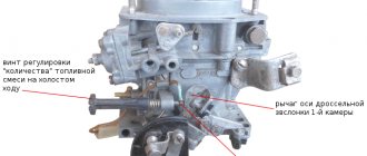
Design and operation of the carburetor: 1 - adjusting screw of the starting device; 2 — lever pin 24, included in the groove of lever 3; 3 — air damper control lever; 4 — screw securing the air damper drive rod; 5 - adjusting screw for slightly opening the throttle valve of the first chamber; 6 — throttle lever of the first chamber; 7 — axis of the throttle valve of the first chamber; 8 — throttle drive lever of the second chamber; 9 — adjusting screw for the amount of idle mixture; 10 — axis of the throttle valve of the second chamber; 11 — throttle lever of the second chamber; 12 — pipe for suction of crankcase gases into the rear throttle space of the carburetor; 13 — throttle valve of the second chamber; 14 — outlet openings of the transition system of the second chamber; 15 — throttle body; 16 — sprayer of the main dosing system of the second chamber; 17 — small diffuser; 18 — fuel nozzle housing of the transition system of the second chamber; 19 — accelerator pump nozzle; 20 — fuel supply pipe to the carburetor; 21 — econostat sprayer; 22 — air damper; 23 — starting rod; 24 — air damper lever; 25 — starter cover; 26 — lever pin 24, operating from the rod 23 of the starting device; 27 — air damper axis; 28 — carburetor cover; 29 — tube with econostat fuel jet; 30 — fuel filter; 31 — needle valve; 32 — emulsion tube of the second chamber; 33 - float; 34 — main fuel jet of the second chamber; 35 — accelerator pump bypass jet; 36 — throttle valve drive lever; 37 — accelerator pump drive lever; 38 — accelerator pump diaphragm; 39 — adjusting screw for the quality (composition) of the idle mixture; 40 — vacuum intake pipe of the vacuum ignition timing regulator. 41 — carburetor housing. 42 - solenoid shut-off valve; 43 — adjusting screw for additional air for factory adjustment of the idle speed system; 44 - trigger diaphragm.
A float carburetor consists of many elements:
- Float chamber to maintain fuel at a given level.
- A float equipped with a special needle, which is used to dose the level of gasoline.
- Mixing chamber - for mixing finely dispersed fuel with air.
- A diffuser is a narrowed area to increase air speed.
- A sprayer equipped with a nozzle that connects the chambers delivers the mixture to the diffuser.
- Throttle valve - to regulate the flow of working fluid.
- Air damper - to regulate the flow of air entering the carburetor. Using the element, a “rich”, “normal” or “poor” mixture is created.
- Idle system - supplies fuel past the mixing chamber through special channels into the throttle space.
- Econostats and economizers provide additional fuel supply under significant loads. Econostats operate from air rarefaction, economizers are controlled forcibly.
- Fuel suction - for forced enrichment of the fuel mixture. Using the lever, the driver opens the throttle slightly, air passes through the mixing chamber and takes in more fuel. As a result, the mixture becomes richer, helping to start a cold engine.
Carburetor control
As a rule, the actions of the carburetor are controlled by the driver of the car. Some models of carburetors used auxiliary systems that slightly automated carburetor control.
In order to control the throttle valve, the gas pedal is most often used, which determines its mobility with the assistance of a rod system or cable drive. Traction is usually better, but the drive mechanism is much more complex and hinders the mechanism’s ability to arrange the engine compartment area. Rod drive was popular until 1970, then metal cables began to be used more often.
On older cars, a dual carburetor throttle valve drive system was often assumed: manually using a lever or from the foot using a pedal. If you press on the pedal, the lever does not move, but if you move the lever, the pedal goes down.
Subsequent opening of the throttle can be done using the pedal. When the pedal is lowered, the throttle remains in the same position in which it was fixed when controlled by hand. For example, on the Volga GAZ-21, a lever was placed on the instrument panel to control the hand; by moving it, you can achieve constant operation of a cold engine without the action of the air damper, or use “constant gas”. On trucks, "constant throttle" was used to make reversing easier.
We recommend: Shelf life of engine oil in the canister and engine
The air damper can be equipped with a mechanical or automatic drive. If the drive is mechanical, then the driver closes it using a lever. The automatic drive is very popular in other countries, but in Russia it has not “taken root” due to its unreliability and short service life.
The principle of operation of the carburetor
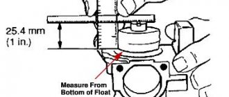
First, the fuel is sent to the float chamber. When the required level is reached, the float rises and closes the valve through which fuel is supplied. When the float drops, the fuel supply resumes.
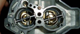
Next, the fuel goes into the mixing chamber, where a combustible mixture is created. Air is supplied from above, which combines with the fuel. The chamber contains a spray tube with a jet, as well as a throttle and diffuser. The jet is a plug that prevents fuel from leaking out of the float chamber. The damper connected to the pedal is called the throttle. When pressed with your foot, it opens and the combustible mixture enters the cylinder. As a result, the car picks up speed. The diffuser contains a distribution tube.
At the moment of start-up, a vacuum is formed in the mixing chamber, and fuel is sprayed from the atomizer. A flow of air rises, which, when mixed with fuel, transfers the fuel into the cylinder.
In addition to the mixing and float chambers, the newest devices also contain a starting and dosing device, an idle design, an economizer, and an accelerator pump. Outdated models do not provide full engine operation, since depending on whether the engine is cold or hot, the mixture must be different. If a cold engine is started, a fuel-rich mixture is required. In cases where the engine has been running for a long time, a mixture with a small amount of fuel is required.
To increase speed or drive in a loaded car, you need a mixture highly enriched with fuel. A similar situation occurs when driving at idle, at low speeds. A simple carburetor cannot provide such conditions.
To enrich the mixture with fuel, an accelerator pump is used. When the pedal is pressed sharply, air passes through, which moves faster than the fuel. This is due to the lack of fuel in the flammable liquid. With a pump, the power unit works more powerfully.
The idle system is ideal for low speeds. In this mode, the power unit operates on a rich mixture. However, a metering system alone is not enough, because at idle the throttle opens only partially. In the newest carburetors, the combustible mixture is formed near the throttle, since in this place, even if the throttle is not fully open, the necessary vacuum is created.
To start the engine, a mixture that is enriched with fuel is required. For this purpose, a damper with a valve is provided in the mixing chamber through which air passes. There is a knob on the dashboard of the car to control the valve. When the handle is pulled out, the valve opens slightly and the volume of air in the mixing chamber decreases. And the amount of fuel in the mixture increases. As a result, even the first portions of the mixture are sufficiently saturated, and the engine starts quickly. With a trigger, the engine runs even at low temperatures.
The capabilities of the dosing device allow you to create a mixture suitable for engine operation in different modes. Using the system, the mixture composition is automatically adjusted when the engine is running at low and medium loads. In this mode, fuel is supplied through a metering system. However, even with the throttle fully open, there is often not enough fuel. For this reason, when the throttle is almost fully open, the lever connected to it acts on the economizer drive rod - this opens an additional passage from the float chamber. As a result, the engine operates more powerfully.
How to profitably exchange a used car
To guarantee the legality of the used car exchange service and its objective cost, the purchase and sale process should be carried out at a trusted auto center. Here the client will be offered:
- Diagnostics of the old model, on the basis of which its cost will be determined;
- Selection of cars for exchange, completely new or with a clean mileage history: all cars undergo forensic examination, therefore the car dealership will never sell a car with a “dark past”;
- Legal support of the transaction: the client enters into a notarized agreement and, if necessary, can use the credit services of the car dealership’s partner bank;
- Efficiency of the service: the client does not need to look for buyers for his vehicle; he does not need to settle issues with the traffic police or the bank. The listed functions are the task of the auto center.
Read here! Valve adjustment procedure
Thus, with minimal documents, it is possible to buy an improved car within one to three days. The used car exchange service makes it possible to regularly change the owner’s vehicle fleet by purchasing its best models.
Classification of carburetors
All carburetors can be distinguished by the following characteristics:
- Based on the direction of flow, horizontal and vertical models are distinguished.
- Based on the adjustment of the nozzle hole and the formation of vacuum, they are divided into: systems with constant vacuum; with constant cross-section (serial devices); with spool throttling - models for motorcycles, in them, instead of a throttle valve, the volume of the incoming mixture is regulated by a slide valve.
- Depending on the number of mixing chambers, single- and multi-chamber models are produced. "Twin" devices are used in engines with cylinders that are far apart from each other. As a result, each half injects into its own cylinders.
Carburetors. The operating principle of a simple carburetor
Carburetors. The operating principle of a simple carburetor
The process of preparing a combustible mixture of fuel and air outside the engine cylinder is called carburetion. The device that carries out this process is called a carburetor.
Carburetors can be of three types: evaporative, injection and float suction. Evaporative carburetors are designed to operate on easily evaporating fuel. Air passing over the surface of the fuel is saturated with its vapors and forms a combustible mixture.
An injection (or membrane) carburetor has a rather complex design consisting of two high and low pressure fuel chambers, separated by a first membrane, respectively, as well as two air chambers - high and low pressure, separated by a second membrane. Under the influence of the pressure difference, the elastic membrane bends and fuel enters the fuel chamber through the gas pump.
The most widely used are float suction carburetors with fuel suction at a vacuum that occurs in the narrowed part of the carburetor air channel - the diffuser due to a local increase in air flow speed.
In the body of a simple carburetor there is a float chamber 6 and a mixing chamber 1. Float 8, acting on the needle valve 7, maintains a constant fuel level in the float chamber. Hole 5 communicates the float chamber with the atmosphere.
Rice. Diagram of the design and operation of a simple carburetor
1 – mixing chamber, 2 – diffuser, 3 – air pipe, 4 – sprayer, 5 – air hole of the float chamber, 6 – float chamber, 7 – needle valve, 8 – float, 9 – jet, 10 – throttle, 11 – inlet engine pipeline. , 12 – throttle lever.
In the upper part of the mixing chamber there is an inlet air pipe 3, in the middle there is a diffuser 2 having a narrowed flow area (neck), and in the lower part (outlet pipe) there is a damper 10, called a throttle, mounted on a roller passed through holes in the walls of the mixing chamber. Using lever 12 at the outer end of the throttle shaft, the throttle can be turned to the required position. The outlet pipe of the mixing chamber is connected to the inlet pipe 11 of the engine via a flange.
Carburetor is simple
This article clearly describes the principles of operation of a carburetor, how it works, and all this is done in a clear and accessible form, with illustrations and detailed descriptions. So if you have little idea what a carburetor is and what it is used for, but want to figure it out, this article is for you!
COMPOSITION OF COMBUSTIBLE MIXTURE For the operation of an internal combustion engine, a mixture of fuel and air is required. In carburetor engines, fuel (gasoline) is mixed with air in a certain proportion outside the cylinders and, having partially evaporated, forms a combustible mixture. This process is called carburetion, and the device that prepares such a mixture is called a carburetor. The mixture, passing through the intake pipe, enters the engine cylinders, where it mixes with the remaining hot exhaust gases, forming a working mixture. Particles of atomized fuel evaporate. To start the engine and operate it in different modes, a different composition of the combustible mixture is required. Therefore, the carburetor is designed in such a way that it allows you to change the quantitative ratio of atomized fuel and air in the mixture entering the engine cylinders. For complete combustion of 1 kg of fuel, about 15 kg of air is required. A fuel-air mixture in this proportion is called normal. The engine operating mode with this mixture has satisfactory indicators in terms of efficiency and developed power. A slight increase in the amount of air in the air-fuel mixture compared to its normal content (but not more than 17 kg) leads to a lean mixture. With a lean mixture, the engine operates in the most economical mode, i.e. Fuel consumption per unit of developed power is minimal. The engine will not develop full power with such a mixture. If there is excess air (17 kg or more), a lean mixture is formed. The engine runs unstably on such a mixture, and fuel consumption per unit of power output increases. With an over-lean mixture containing more than 19 kg of air per 1 kg of fuel, engine operation is impossible, since the mixture does not ignite from a spark. A slight lack of air in the air-fuel mixture compared to normal (from 15 to 13 kg) contributes to the formation of an enriched mixture. This mixture allows the engine to develop maximum power with slightly increased fuel consumption. If the air in the mixture is less than 13 kg per 1 kg of fuel, the mixture is rich. Due to lack of oxygen, the fuel does not burn completely. An engine with a rich mixture operates in an uneconomical mode, intermittently and does not develop full power. An over-enriched mixture containing less than 5 kg of air per 1 kg of fuel does not ignite - engine operation on it is impossible. STARTING THE ENGINE When starting a cold engine, part of the sprayed fuel settles on the walls of the intake manifold, and part of the evaporated fuel, having entered the cylinders, condenses on the walls. In addition, at low air temperatures, mixture formation worsens, since the evaporation of gasoline slows down. Therefore, to start a cold engine, it is necessary for the carburetor to prepare a re-enriched air-fuel mixture. IDLE OPERATION At idle speed, the engine speed is low and the carburetor throttle valves are almost completely closed. Because of this, cylinder ventilation is not as effective as compared to operation at medium and high crankshaft speeds and the amount of combustible mixture entering the engine is small. The working mixture contains a large amount of exhaust (residual) gases. Therefore, for stable engine idling, a rich mixture is required. PARTIAL LOAD MODE During partial load operation, the engine does not require full power. The throttle valves are not fully open, but the ventilation of the cylinders is good. Therefore, in this mode, a lean combustible mixture is sufficient. The ratio of the power developed by the engine to the amount of fuel consumed allows us to consider the partial load mode the most economical. LOAD MODE At full load, the engine requires maximum or near maximum power. At the same time, the engine operates at high speeds, and the throttle valves are fully (or almost completely) open. This mode requires an enriched mixture with an increased combustion rate. SHARP LOAD INCREASE MODE When the engine operates under a sharp load increase, for example when accelerating a car, a rich mixture is required. But since the mixture formation process has some inertia, in order to prevent the occurrence of a “failure” when accelerating, additional short-term enrichment of the combustible mixture is required. To do this, additional fuel is injected directly into the carburetor mixing chamber.
Modern carburetors are equipped with a dozen different systems and devices that have an extensive network of channels, numerous calibrated holes, complex lever transmissions and pneumatic chambers. It’s not easy to understand this intricacy right away. Therefore, it is useful to consider all the main systems separately using simplified diagrams as examples. And you should start with the operating principle and design of a simple carburetor.
To operate a gasoline engine, it is necessary to add fuel to the intake air, which then burns in the cylinder during the working stroke of the piston. In order for the fuel to reliably ignite and burn completely, it is necessary to thoroughly mix it with air and at the same time maintain the optimal composition of the combustible mixture in all engine operating modes. These functions are performed by a carburetor connected by an inlet pipe to the engine cylinders. The simplest carburetor consists of two chambers: a float chamber and a mixing chamber. The process of preparing a combustible mixture continues along the entire path of movement of fuel and air along the intake tract, right up to the cylinders, but begins with atomization of fuel in the carburetor mixing chamber. For this purpose, a tube-shaped sprayer is installed in the mixing chamber. The tube section is brought to the center of the chamber diffuser. A diffuser is a narrowing section of the mixing chamber. The air flow speed in the diffuser increases, and a vacuum occurs at the atomizer. Under the influence of this vacuum, the fuel flows out of the atomizer and is intensively mixed with air. Fuel enters the atomizer from the float chamber, with which it is connected by a channel. A nozzle is installed in the channel - a plug with a through hole of a certain size and shape. The jet restricts the flow of fuel into the atomizer. One of the conditions for normal operation of the carburetor is the correct setting of the fuel level in the float chamber. The fuel level in the chamber is maintained using a float mechanism with a needle valve. Fuel is supplied to the float chamber through the fuel line. As the chamber fills, the float rises and the needle closes the valve hole, while the air displaced by the fuel is discharged out through a special hole. The float chamber and the sprayer are communicating vessels. The fuel level in the float chamber is set so that it is just below the nozzle exit. At an increased level, the fuel will leave the atomizer, over-enriching the mixture; at a low level, the supply of fuel to the atomizer is insufficient, resulting in the formation of a very lean combustible mixture. In order to change the composition of the mixture, an air damper is installed in the mixing chamber above the diffuser. As the choke valve closes, the mixture will become richer. Excessive closing of the throttle will lead to over-richness of the mixture and engine shutdown. To regulate the amount of air-fuel mixture entering the cylinders, a throttle valve is installed in the lower part of the mixing chamber. When the air and throttle valves are fully open, there is minimal resistance to air flow. The simplest carburetor prepares a combustible mixture of optimal composition only in a certain range of crankshaft speeds. The range depends on the jet capacity, diffuser cross-section, fuel level and throttle position. An automobile engine must operate over a wide range of crankshaft speeds and under constantly changing loads. To prepare a mixture of optimal composition in all possible operating modes, automobile carburetors are equipped with additional systems.
The main metering system of the carburetor is designed to supply the main amount of fuel in all engine operating modes, except idle mode. At the same time, at medium loads it should ensure the preparation of the required amount of lean mixture of approximately constant composition. In the simplest carburetor, as the throttle valve opens, the increase in air flow passing through the diffuser is slower than the increase in fuel flow flowing from the atomizer. The combustible mixture becomes rich. To prevent over-enrichment of the mixture, it is necessary to compensate its composition with air, depending on the degree of opening of the throttle valve. In a carburetor, such compensation is carried out by the main metering system. In Solex carburetors, compensation is carried out by pneumatic braking: fuel enters the atomizer not directly from the float chamber, but through the emulsion well - a vertical channel in which the emulsion tube is installed. The walls of the tube have holes for the exit of air entering it from above through an air nozzle. The flow of fuel into the emulsion well is determined by the fuel nozzle. In the emulsion well, the fuel is mixed with air coming out of the holes in the emulsion tube. As a result, fuel emulsion enters the atomizer rather than pure fuel. As the throttle valve opens, the vacuum in the diffuser increases and the flow of emulsion from the atomizer increases. At the same time, the flow of air into the emulsion well through the air nozzle increases, which reduces the flow of fuel from the float chamber through the fuel nozzle. The amount of fuel passing through the nozzle corresponds to the amount of air entering the diffuser, which ensures compensation of the mixture composition. The required composition of the combustible mixture is determined by the selection of the flow sections of the fuel and air nozzles, as well as the type of emulsion tube.
In the simplest carburetor, the float chamber is connected to the atmosphere through a hole in the cover. During operation, as the air filter becomes dirty, the vacuum in the diffuser of such a carburetor will increase and, consequently, the mixture will begin to become richer. To eliminate the influence of air filter contamination on the composition of the combustible mixture, the internal cavity of the float chamber is connected by a channel to the carburetor neck.
For. running the engine at idle speed with a minimum crankshaft speed requires a small amount of combustible mixture. Therefore, the throttle valve should be almost completely closed. In this case, the vacuum in the diffuser is not enough for the main dosing system to start operating. Therefore, the carburetor is additionally equipped with an idle system, which prepares the air-fuel mixture in an amount that ensures stable engine operation with the throttle valve closed. The channels of the idle system connect the throttle space (the cavity of the intake pipe) with the emulsion part of the mixing chamber. When the engine is idling, a high vacuum forms under the throttle valve. Under the influence of vacuum, fuel from the emulsion well passes into the idle fuel channel, where it is mixed with air entering through the air channel from the upper part of the mixing chamber. The ratio of fuel and air in the emulsion is determined by the throughput of the fuel and air jets, which are installed in the idle channels. Next, the emulsion enters the throttle space, where it mixes with air passing through the gap between the chamber wall and the damper. The gap is adjusted with the “quantity” stop screw (SOLEX). The amount of fuel emulsion passing through the channel into the throttle space is regulated by a screw with a cone-shaped tip (a “quality” screw). When tightening the screw, the flow area of the channel decreases. And vice versa. When the throttle valve is gradually opened, the air flow through the mixing chamber increases, but the amount of incoming emulsion remains at the same level. The vacuum in the diffuser is still not enough for the main dosing system to start working. As a result, the mixture becomes leaner and a “failure” is observed in the engine’s operation. To ensure a smooth transition from idle to medium load mode, a transition system is used, which is combined with the idle system. The transition system channel connects the emulsion channel of the idle system with the over-throttle space of the mixing chamber. The outlet of the channel is located in such a way that, after opening the throttle valve, it appears in the vacuum zone; through it, an additional amount of emulsion enters the mixing chamber, smoothing the transition from one engine operating mode to another. At idle, when the throttle valve is closed, some of the air is mixed into the fuel emulsion through the transition system channel. Changes in the composition of the mixture are compensated by the selection of jets. When turning the “quantity” screw, the throttle valve opens slightly. As a result, the air flow through the channel of the transition system decreases, and through the gap between the walls of the mixing chamber and the damper increases. The amount of combustible mixture entering the engine increases, and the crankshaft speed increases. When the screw is unscrewed, the damper closes and the crankshaft speed decreases.
The main metering system ensures smooth engine operation only when the throttle valve is opened very smoothly. When the damper is opened abruptly (for example, for intense acceleration of a car), the mixture formation process is initially disrupted. To eliminate “failure” in engine operation in this mode, the carburetor is equipped with a special device - an accelerator pump. It is designed to briefly enrich the combustible mixture when the throttle valve is opened sharply. On carburetors, a diaphragm-type accelerator pump driven by the throttle axis is widely used. When the damper opens, a cam mechanically connected to its axis rotates and presses the diaphragm pusher. When the throttle valve closes, the cam stops acting on the pushrod. The diaphragm, under the action of the return spring, moves to its original position, creating a vacuum in the pump cavity. The discharge valve ball closes the hole in the well under the atomizer, and the suction valve ball allows fuel to flow into the pump. Gasoline from the float chamber passes through the suction valve, filling the pump cavity. When you sharply press the gas pedal, the cam presses on the telescopic pusher, compressing its spring. In this case, the discharge valve ball rises under fuel pressure, opening the way for fuel from the pump cavity to the atomizer. There is no sudden movement of the diaphragm, because fuel cannot pass quickly through the small nozzle outlet. Since the pusher spring is stiffer than the return spring of the diaphragm, the former, overcoming the resistance of the latter, moves the diaphragm, displacing a portion of fuel through the injection valve and nozzle into the carburetor mixing chamber. The injection process takes up to several seconds. This ensures stable operation of the engine when accelerating the car, and, in addition, the diaphragm is protected from rupture under the influence of fuel pressure.
When starting the engine, the crankshaft speed is low, the vacuum in the intake system is low, and gasoline does not evaporate well. In addition, as noted earlier, on a cold engine, especially at low ambient temperatures, most of the resulting fuel vapor condenses in the intake tract. Therefore, for a stable engine start, it is necessary to prepare a knowingly over-enriched air-fuel mixture in the carburetor. To do this, close the air damper and open the throttle slightly. Then a vacuum is created in the diffuser, sufficient for the required amount of fuel to flow out of the nozzle even when the crankshaft rotates slowly. A working mixture suitable for starting the engine is formed. But as soon as the first flashes appear in the cylinders, so that the engine does not stall from over-enrichment, it is necessary to open the air damper slightly, opening the way for air to enter the diffuser. To perform these operations, the carburetor is supplemented with a special starting device. On carburetors of domestic car engines, a manually controlled starting device is widely used. It consists of an air damper, an automatic device for opening it slightly and drive elements. The driver closes the air damper from inside the car using a handle, which is connected by a rod to the damper drive. The actuator allows the damper to open slightly, and the return spring tends to keep it in the closed position. The carburetor is equipped with a device that automatically opens the air damper to the required amount, which prevents the fuel mixture from becoming over-rich immediately after start-up. The device consists of a chamber with a diaphragm, a spring and a rod. The chamber is connected through a channel to the rear throttle space of the carburetor. With the beginning of stable engine operation, a sharp increase in vacuum occurs behind the throttle valve, from where it is transmitted through the channel to the chamber. The diaphragm, overcoming the resistance of the spring, moves and through the rod opens the air damper, leaning the mixture. Due to the fact that the damper is mounted asymmetrically on the axis, under the influence of vacuum, it tends to open in the mixing chamber, “helping” the starting device. The air damper is connected to the throttle valve by a mechanism that ensures that the throttle valve opens slightly when the air valve is completely closed. The amount of throttle valve opening should ensure stable operation of a cold engine when warming up. As the engine warms up, the driver manually opens the air damper and closes the throttle, reducing the crankshaft speed to the minimum stable speed.
To obtain maximum power from the engine, a rich fuel mixture is required. To prepare it, the carburetor is equipped with a special system called a power mode economizer. The system ensures that additional fuel enters the atomizer, bypassing the main fuel jet. To turn on the power mode economizer, a pneumatic or mechanical drive is used. The pneumatic actuator is activated when the vacuum in the mixing chamber drops, and not as the throttle valve opens. This makes it possible to enrich the mixture to the required extent when accelerating the car, ensuring good throttle response, and maintaining a lean mixture during uniform movement, ensuring efficiency. When the throttle valve is closed, the vacuum from the throttle space flows through the channel to the economizer diaphragm. In this case, the diaphragm compresses the return spring, and its pusher does not touch the economizer valve ball, and the valve is closed. When the throttle valve is opened, the vacuum under it (and therefore at the diaphragm) decreases. Under the action of the spring, the diaphragm moves, and its pusher, recessing the valve ball, opens the economizer channel. Additional fuel from the float chamber enters the nozzle of the main metering system, enriching the mixture.
The econostat is designed to further enrich the combustible mixture at maximum load conditions at high crankshaft speeds. An econostat is a sprayer installed at the very top of the mixing chamber, above the diffuser. Fuel is supplied into it directly from the float chamber through a channel in which a fuel nozzle is installed, which prevents over-enrichment of the combustible mixture. Sometimes, to fine-tune the economizer, an air jet is additionally installed in the upper part of the channel. Air is supplied through it, which is mixed with fuel in the channel. Since the nozzle outlet is located in a low-pressure zone, the economizer only comes into operation when the throttle valve is fully opened. In this case, the crankshaft rotation speed must be high enough to create a vacuum in the area of the nozzle outlet hole sufficient to raise the fuel in the channel to the level of the nozzle. The fuel entering through the atomizer is mixed with the flow of the fuel-air mixture, further enriching it.
To improve mixture formation and distribution of the combustible mixture among the cylinders, it is necessary to ensure low resistance to air movement through the carburetor diffuser at high loads and maintain sufficient vacuum in it at low loads. These requirements are best met by the design of a two-chamber carburetor with sequential chambers. The first chamber - the main one - ensures engine operation at idle, as well as at low and medium loads. The second - additional - is activated under heavy loads. The throttle valve drive of the second chamber can be mechanical or pneumatic. In the first case, the beginning of opening of the second chamber damper occurs at a certain opening angle of the first chamber throttle valve. In the second case, the opening moment depends on the magnitude of the vacuum in the mixing chambers. We discuss the article here https://www.semerka.info/forum/viewtopic.php?p=14392#14392 Mr.Ice especially for www.semerka.info
The simplest carburetor device and principle of operation
The simplest carburetor consists of two main parts: a mixture-forming device and a float chamber. In the mixture-forming device, a flammable mixture is prepared, and the float chamber is a reservoir from which fuel is supplied to be mixed with air.
The carburetor's mixture-forming device has an air inlet, a diffuser, a mixing chamber, a throttle valve, and an outlet. The outlet pipe usually ends in a flange that secures the carburetor to the engine intake manifold.
Advantages and disadvantages of a carburetor
The main advantage of a carburetor is its maintainability. You can purchase a repair kit for this device, which can be replaced, if necessary, even on the street. However, this advantage has long lost its practical meaning: the development of computer diagnostics has made injector repair an activity almost equivalent in simplicity. The diagnostic program can even be installed on an iPhone, and errors can be successfully read using an adapter cable.
The disadvantages of a carburetor are due to the fact that it is a rather thin and complex mechanical device. It must be adjusted from time to time, cleaned and protected from blockages. In addition, its operation depends on weather conditions: in winter, condensation can freeze in it, in summer it overheats, and the fuel begins to evaporate rapidly. In general, we can say that this device is morally outdated.

