Removing the gearbox
Place the car on a lift or inspection ditch.
Raise the engine hood and fix it in this position. From inside the engine compartment, perform the following operations:
- disconnect the wires from the battery, from the starter traction relay and the ground wire from the gearbox housing;
- disconnect the cable from the clutch release fork and the rear cover of the gearbox (see section “Clutch”);
- unscrew the two upper bolts securing the clutch housing to the engine block (one of them secures the upper part of the starter), disconnect the speedometer drive cable from the drive gear, remove the oil level indicator from the socket of the gearbox cover.
Working from below the car, perform the following operations:
- drain the oil from gearbox 2 (Fig. 80), disconnect the wires from the reverse light switch 3, loosen the clamp 12 and disconnect the rod 13 from the gear selection rod hinge;
- unscrew the nut securing the torque rod 14 to the gearbox and disconnect the jet rod, hang the rods 13 and 14 from the body;
- disconnect the ball joints 8 of the suspension arms from the steering knuckles, the suspension arms 10 and braces 11 from the subframe 1, disconnect the steering rods from the steering arms;
- using a puller 67.7801.9524 or sharply hitting the inner joint body with a hammer through a drift, knock out the hinges from the semi-axial gears and move the shafts 9 of the wheel drives to the side. If it is difficult to separate the wheel drive from the side gear, remove the gearbox assembly with the wheel drive and on a workbench, using the same puller, press the hinge out of the side gear;
- unscrew the lower starter mounting bolt and remove it;
- unscrew the side bolts securing the clutch housing to the engine block, using a special wrench for the rear right bolt;
- disconnect the power unit suspension bracket 4 from the bracket 6 of the longitudinal pipe 5 of the subframe;
- disconnect the left longitudinal pipe 6 (Fig. 81) of the subframe from the body, from the cross member of the subframe and the support 4 of the steering mechanism and remove it;
- supporting the gearbox by the ring using a hoist or another method, move the gearbox assembly with the clutch housing away from the engine in order to separate the gearbox input shaft and the clutch driven disc;
- remove the gearbox. In this case, you cannot rest the primary pin on the petals of the pressure spring, so as not to damage them.
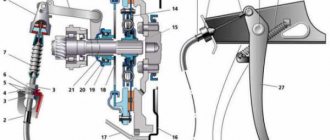
Rice. 80. Mounting the gearbox on the car:
1 — subframe; 2 — gearbox; 3 — reverse light switch; 4 — power unit suspension bracket; 5 — left longitudinal pipe of the subframe; 6 — subframe bracket for mounting the power unit; 7 — suspension strut; 8 — ball joint of the suspension arm: 9 — wheel drive shaft; 10 — suspension arm; 11 — suspension arm extension; 12 - clamp; 13 — gearbox control drive rod; 14 - jet thrust.
Rice. 81. Subframe:
1 — head for attaching the subframe to the body; 2 — bracket for fastening the power unit; 3 — suspension arm mounting bracket; 4 — steering gear support; 5 - bracket for fastening the suspension arm extension, 6 - detachable subframe pipe; 7 — bracket for fastening the stabilizer bar.
Transmission
- keys “10”, “13”, “17” and “19”
- gearbox support
Before starting work
Disconnect the wire from the “–” terminal of the battery. Drain the gearbox oil. Remove the starter. Loosen the hub nuts and front wheel nuts.
1.
Unscrew the nut securing the end of the “mass” wire to the gearbox and.
2.
. disconnect it from the gearbox.
3.
Disconnect the drive cable from the clutch release fork and the bracket on the rear cover of the gearbox and move it to the side
(see subsection 11.2.6.) .
4.
After unscrewing the fastening nut, disconnect the speedometer drive cable from the gearbox.
5.
Remove the upper bolt securing the gearbox to the engine.
6.
Please note: there is a spring washer installed under the bolt head.
7.
Disconnect the block with wires from the reverse light switch.
8.
Unscrew the three fastening bolts (spring washers are installed under the bolt heads) and.
9.
. remove the lower clutch housing cover.
10.
Using a second wrench, hold the torque rod mounting bolt from turning and unscrew the nut.
11.
Please note: there are spring and flat washers installed under the nut.
12.
Disconnect the torque rod from the gearbox by removing the bolt.
13.
Loosen the clamp securing the gear shift rod to the gear selector rod hinge.
14.
Unclench the clamp using a screwdriver.
15.
Disconnect the gear shift rod from the gear selector rod joint.
16.
Hang both rods to the exhaust pipe.
17.
Unscrew the two nuts securing the steering gear support to the left longitudinal pipe of the subframe.
18.
Unscrew the two nuts securing the cross member to the subframe.
19.
Please note: There is a spring washer installed under each nut.
20.
Remove the cross member from the studs.
21.
Unscrew the hub nuts and remove the shanks of the outer hinges from the hubs of both front wheels
(see subsection 11.3.1.) .
22.
On the left side, holding the bolt securing the stabilizer bar to the lever with a second wrench, unscrew the nut (there is a spring washer installed under the nut).
23.
Disconnect the strut from the suspension arm by removing the bolt.
24.
After unscrewing the two fastening nuts, remove the stabilizer bar mounting bracket on the left side from the studs.
Replacing a clutch disc on an OKA car Through the top
Replacement tricks
clutch
disc on an
OKA
you will learn from this video!
- wheels. After removal
, they must be twisted and thrown away so that nothing interferes; - release the racks. Replacing the clutch without completely removing the gearbox and > oka > reports replacing the clutch without completely removing it. To do this, you need to remove the steering tips;
- Unscrew the bolts
that secure the ball joint; - Next you need to remove the engine protection using a cable;
- drain all the oil from the box;
- on the rocker, loosen the nut and then remove it;
- Unscrew absolutely all the nuts on both cushions;
- now a jack or other support should be installed under the engine;
- turn off the reverse sensor;
- You need to carefully disconnect the wires from the starter, unscrew the nuts and remove it;
- Unscrew the nuts from the flywheel and fork protection;
- Next is a very important point. Checking and replacing brushes on the generator and VAZ 2107. Service without removing the generator. You need to remove the CV joint, but only on the right side, you don’t need to touch the left one;
- Unscrew the bolts securing the gearbox unit.
- The last step is to get rid of the nut above the right CV joint.
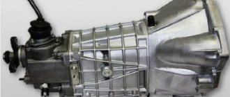
Gearbox "Oka": design and repair
The Oka car (modifications 1111, 11113) is a small car of the first group of the especially small class. Almost all components and mechanisms of the car were borrowed from other proven VAZ models.
The transmission is no exception, since the Oka gearbox essentially resembles the VAZ-2108 transmission, adapted to the engine of this car (size, certain design features, operating parameters).
Read in this article
Clutch OKA
The clutch is a part of the vehicle that facilitates steering, ensures starting the car, as well as changing gears. Replacing the clutch on an OKA car is not much different from replacing a 9 or 10, only the dimensions are slightly smaller. So, in this article we will answer these fairly common questions:
- What is clutch?
- Clutch device on OKA;
- The main malfunctions of the clutch on an OKA car, after which it is necessary to replace it;
- When is it necessary to replace the clutch on an OKA car?
- How is the clutch replaced on an OKA car?
- basic information
- Self-diagnosis
- How to replace the clutch with your own hands?
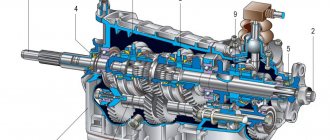
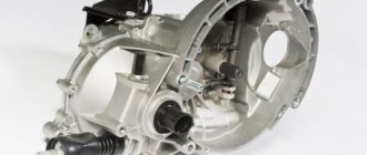
Oka gearbox: main parameters
The basic transmission on the Oka is a two-shaft, four-speed manual transmission with a final drive and differential. The transmission of torque from the internal combustion engine to the drive wheels is carried out through two drive shafts with hinges.
The Oka gearbox and the device diagram using the example of the VAZ-1111 Oka involves a number of components. The Oka checkpoint housing consists of the following elements:
- clutch housing;
- gearbox housing;
- lid.
This box consists of more than 20 parts, the main ones include:
- gears;
- bearings;
- synchronizers;
- oil seals;
- seals;
- sump;
- clamps, etc.;
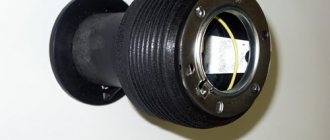
As mentioned above, the Oka gearbox has a remote control; the design includes a gear shift drive, consisting of the following parts:
- floor shift lever;
- ball joint and rod;
- backstage;
- hinges;
- gear selection rod and gear selection mechanisms.
Drive failures, backstage repairs
The box includes many components. The full list of parts is as follows:
- Frame;
- Differential bearing;
- Installation spacer;
- Grease drain plug;
- Semi-axial seal;
- Drive shaft (left);
- Gear 1st speed 2nd. shaft;
- Synchronizer clutch for 1st, 2nd speeds, as well as reverse;
- 2nd speed gear sec. shaft;
- Thrust ring;
- 3rd speed gear sec. shaft;
- Synchronizer clutch for 3rd, 4th speeds, as well as reverse;
- 4th speed gear sec. shaft;
- 4th speed gear thrust ring;
- Bearing;
- 1st and 2nd speed fork axle;
- 3rd and 4th speed fork axle;
- Deut. shaft;
- Reverse fork axle;
- Installation ring;
- Lid;
- Bearing;
- Dipstick;
- Gear 4th speed primary. shaft;
- Gear bearing;
- synchronizer ring for 3rd and 4th speeds;
- Fork;
- coupling;
- Rusk;
- Retainer;
- Plate;
- Bearing;
- Stuffing box;
- Release bearing fork;
- Clutch housing;
- Cap;
- Breather;
- Release bearing;
- Perv. shaft;
- Bearing;
- Sump;
- Main drive driven gear;
- Differential housing;
- Washer;
- Retaining ring;
- Axle gear;
- Speedometer drive gear;
- Speedometer cable;
- Drive shaft (right wheel);
- Speedometer drive housing;
- Satellite;
- Retaining ring;
- Axle of satellites;
- Anther;
- Stock;
Since the Oka gearbox has a remote control, its design additionally includes a drive for the gear selection mechanism.
The drive consists of:
- Gearbox lever (installed in the passenger compartment on the central tunnel);
- Backstage;
- 2 rods (reactive and drive lever);
- Hinge;
- A rod connected to the speed selection mechanism;
The multi-component design of the gearbox drive is not very reliable - over time, adjustment of the connections and repair of the rocker is required.
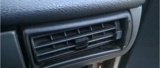
The Oka has problems not only with the gearbox, but also with its drive. The main problems with the drive are the gearshift lever dangling, and it is impossible to turn on any speed.
In the first case, the malfunction lies in the wear of the elements of the link (ball joint). Disassembly, troubleshooting and replacement of worn components allows you to fully restore the functionality of the rocker and eliminate the backlash in it, which is the reason that the lever dangles a lot.
If checking the rocker showed that it is in good condition, you should look and check the hinge mounted on the rod of the control mechanism. The same element can also cause the inability to engage gears. If its tightening clamp is loosened, then the drive rod will rotate in it, but no impact will be transmitted to the control mechanism. Checking the condition of the hinge and tightening the fasteners on it allows you to eliminate problems with the operation of the drive.
The main causes of Oka gearbox malfunctions and frequent breakdowns
The mechanical box of the Eye has a large number of parts, each of which can break. Like any mechanical device, the transmission is not immune to breakdowns. The main causes of Oka gearbox malfunctions include:
- Extraneous noise when shifting the gear shift lever to the neutral position (poor quality lubricant or lack thereof, wear of the input shaft bearings, shaft displacement, etc.). The problem is solved by replacing damaged/worn elements;
- Difficult gear shifting (defect of the cardan joint, damage to the rod lever, etc.). The problem is resolved by replacing damaged parts or adjusting them;
- Spontaneous gear disengagement (wear or damage to gears, deformation of control forks, etc.). The malfunction is eliminated by changing the faulty elements of the box, and the mechanism drive is also adjusted.
You can also separately highlight the causes of malfunctions in the drive mechanism of the Oka gearbox. For example, a malfunction in the operation of the gear shift mechanism occurs for the following reasons:
- Shifting gears is difficult or completely absent (deformation or damage to the hinge of the control mechanism mounted on the rod, loosening of the tension clamp). It is necessary to check the condition of the hinge and tighten the fasteners on it, which usually allows you to restore the functionality of the control mechanism.
- The Oka gear shift lever is not secured well enough (wear of the rocker elements, formation of backlashes in it). The problem is eliminated by troubleshooting or replacing worn elements;
Main breakdowns and their symptoms
The dismantling of the box from the car is carried out in case of certain breakdowns and the need for repairs.
The main types of breakdowns include:
- Breakdown or damage to the housing;
- Damage or wear of gears, synchronizers;
- Bearing wear;
- Bending of the forks of the control mechanism;
The gearbox will also have to be removed if the clutch components are replaced - discs (driver, driven), release bearing or its fork.
Transmission malfunctions appear quite clearly in the form of:
- Increased noise level;
- The appearance of grinding, crunching and other third-party sounds;
- Inability to engage any gear;
- Spontaneous transmission shutdown;
Other malfunctions of the unit include wear of the seals and malfunction of the drive. But these problems do not require removing the gearbox from the car, with the exception of wear on the input shaft seal (it can only be reached from the clutch housing and for this the box must be removed from the car).
How to remove a gearbox on Oka
On the one hand, there are problems that do not require dismantling the box to eliminate. In this case, there is also a group of malfunctions when the box is removed. The box can be dismantled either independently or at a service station by qualified specialists. There are two types of dismantling:
- removing a gearbox without a vehicle's internal combustion engine (without affecting the vehicle's power plant itself, many elements and assemblies are unscrewed and disconnected);
- removing the gearbox along with the vehicle's internal combustion engine (there is a need to drain the technical fluid and disconnect almost all attachments).
The sequence for dismantling the box without removing the internal combustion engine is as follows:
- install the car on an overpass or inspection hole;
- unscrew the nuts securing the drive shafts in the hub and remove the front wheels;
- disconnect the battery terminal and all wires, as well as cables from the box;
- remove the starter and unscrew the fastenings of the lower shield of the mounting housing and then dismantle it;
- unscrew the drive rods and disconnect the steering mechanism supports from the longitudinal beam;
- remove the cross member and pull the drive limit switches out of the hub;
- Unscrew the fastening of the strut and bracket of the left side of the anti-roll bar;
- disconnect the fasteners of the engine support bracket from the box;
- place a stop under the box and remove the left longitudinal beam of the subframe;
- remove the drive shaft end switches from the box and remove the motor support bracket from it;
- Unscrew all fasteners of the gearbox to the internal combustion engine, then move it towards the left wheel and remove the box.
The sequence of dismantling the box together with the internal combustion engine of the car by lowering the components down:
- drain the working fluid (oil) from the gearbox;
- disconnect all elements from the box and the internal combustion engine (cooling system pipes, wiring, etc.);
- disconnect the column from the steering mechanism and tighten the fasteners of the shock-absorbing strut supports;
- Place a wooden pallet underneath the engine;
- to lower the engine, gearbox, steering gear, front suspension and subframe onto a wooden pallet, unscrew all fasteners of the subframe to the car body;
- dismantle the gearbox by lifting the front of the car and pushing it back;
Let us also add that with the help of a lift, dismantling the box together with the car engine can be done by lifting the components up.
Removing the unit from the car
Thanks to its simple design, repairing the Oka gearbox yourself is quite possible. Most often, problems are caused by removing the transmission from a car, rather than repairing it.
Removing the gearbox from the Oka is possible in two ways - only the gearbox itself is removed, or it is removed together with the power plant, and only then the gearbox is disconnected from the engine and undergoes repair.
Each method has its own specific difficulties. In the first case, you have to disconnect the assembly in quite cramped conditions and require unscrewing and disconnecting many components, but the engine is not affected. If removal is carried out together with the power unit, then technical fluids need to be drained and almost all attachments must be disconnected, but removing the motor and gearbox itself is easier.
It is noteworthy that dismantling the box along with the power plant is possible in two ways - by pulling the units up (lifting devices are needed) or by lowering them down.
Removing the gearbox only
Let's look at the algorithm for removing the gearbox using an example when the engine is not affected:
- We place the car on a viewing hole, overpass, or use a lift;
- We tear off and twist the nuts securing the drive shafts in the hub;
- We hang up the front of the car, remove the front wheels;
- Disconnect the battery terminal;
- We disconnect all wires and cables from the box (“mass” wire, plug of the sensor for turning on the reverse signal light, cables);
Checkpoint "Oka"
When designing the VAZ Oka modifications 1111 and 11113, the designers used many solutions tested on other VAZ models. This applies to almost all components and mechanisms of the car, including the transmission.
The designers “ripped off” the Oka checkpoint from the VAZ-2108, one of the main “donors” for the small car. The designers, in fact, took the box from the Eight and adapted it to the Oka engine. Therefore, the VAZ-2108 and Oka gearboxes are almost identical in general design, the main difference comes down to dimensions , certain design features and operating parameters.
Main settings
The VAZ “Oka” 1111 and 11113 gearbox is a two-shaft, 4-speed gearbox, combined with a main gear and a differential. All forward gears are synchronized. The transmission of rotation to the front drive wheels from the gearbox is carried out by means of two drive shafts with joints of equal angular velocities. The weight of the unit is only 24.5 kg.
Due to the transverse location of the power plant, the gearbox is controlled remotely.
Both modifications of the small car received gearboxes identical in design, so the gear ratios are the same, the difference between the Oka gearbox 1111 and 1113 is only in the final drive indicators:
VAZ 11113
Removing the gearbox
We carry it out on an inspection ditch or a lift.
- Disconnect the negative cable from the battery.
- Drain the oil from the gearbox (see “Changing the oil in the gearbox”).
- Disconnect the clutch cable from the gearbox.
- Disconnect the reverse light switch connector.
- Disconnect the speedometer cable from the drive.
- We knock out the inner hinge of the right drive without disconnecting the drive from the wheel.
- We remove the left drive completely (see “Removing the front wheel drives”).
- We disconnect the gear shift drive rod from the rod joint and the reaction rod from the gearbox
, remove the starter and the left support of the power unit. - Using a 13mm socket, unscrew the left and loosen the right nuts securing the rear cross member of the subframe.
- We move the crossbar back.
- Using a socket and a 13mm wrench, unscrew the nuts of the two bolts securing the removable (left) subframe pipe to the front cross member.
- We take out the bolts
- Using a 13mm socket, unscrew the two nuts securing the left stabilizer bar bracket to the subframe pipe.
- Remove the bracket.
- Using two 17mm spanners, unscrew the nut of the bolt securing the left stabilizer bar strut to the suspension arm.
- We take out the bolt.
- Using two 13mm spanners, unscrew the two nuts of the bolts on the left securing the steering gear bracket to the subframe pipe.
- Using a 19mm socket, unscrew the bolt on the left securing the subframe pipe to the body.
- Remove the subframe pipe assembly with the lever extension and the lever with the ball joint.
- Using a 10mm socket, unscrew the two bolts securing the clutch housing cover to the rear oil seal holder.
- Using a 10mm wrench, unscrew the bolt securing the cover to the clutch housing.
- Remove the cover.
- Using a 13mm wrench, unscrew the nut securing the earth wire to the gearbox.
- We remove the wire.
- Using a 17mm spanner, unscrew the lower bolt of the front fastening of the gearbox to the engine and the lower bolt of the rear fastening, located above the inner hinge of the right-hand drive (the bolt can be finally removed after dismantling the rear support of the power unit).
- Having unscrewed the upper bolt securing the gearbox to the engine with a “17” head, we move it away from the engine, disconnecting the input shaft of the box from the driven clutch disc, and remove the box.
ATTENTION! When removing or installing the gearbox, do not rest the input shaft on the clutch pressure spring leaves to avoid damaging them.
We install the gearbox in the reverse order.
Before installing the box, apply a thin layer of CV joint-4 grease to the splined end of the input shaft and the outer surface of the clutch release (release) bearing guide sleeve.
After installing the gearbox, we adjust the clutch drive (see “Replacing and adjusting the clutch cable”) and the gearbox control drive (see “Removing the gearbox control drive”). Pour oil into the box.
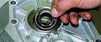
Replacing oil seals
Most often, the drive shaft oil seals located at the installation site of the internal hinge limit switches in the gearbox must be replaced. A sign of wear is indicated by the presence of transmission oil leaks on the inner CV joint and adjacent surfaces of the housing.
Replacing gearbox seals is a relatively simple operation, but requires complete dismantling of the drive shafts.
The work algorithm is as follows:
- We install the car on the pit;
- We tear off and twist the nuts holding the drive in the hub;
- We hang up the front of the car and remove the wheels;
- We disconnect the steering tip and the ball joint from the hub;
- By pulling the hub to the side, we remove the end switch of the outer CV joint from it;
- We climb under the car;
- Using a hammer and a socket, we strike the end of the inner CV joint until the retaining ring installed on the end comes out of the groove;
- Remove the drive shaft assembly;
- Use a screwdriver to pry off the “old oil seal;
- We install a new seal using a mandrel;
- We install the drive in place;
- We assemble the car;
Replacement of gearbox Lada 1111 Oka (VAZ 1111 Oka)
- Equipment and tools
Particularly small class cars VAZ and SeAZ “Oka” 1111 and 1113 were the only models of the domestic automobile industry that were equipped with two-cylinder water-cooled power plants. These motors were very compact and structurally very well made.
But, like any power unit, Oka engines required major repairs after long-term operation. Moreover, some of the restoration work, especially the crank mechanism and the cylinder-piston group, is much easier to perform with the engine removed, so you definitely need to know how to remove the engine from the Oka. In general, removing the engine from the Oka is not a difficult operation, but you need to know the sequence of actions. You will also need the appropriate equipment.
Transmission repair (Video)
VAZ cars (KAMAZ, SeAZ)-1111, 11113.
This operation is performed when the clutch does not fully engage or disengage (slips or drives) and the defect cannot be eliminated by adjustments. We have written in detail about signs of wear or clutch malfunction more than once, for example, in magazine No. 9 for 1995 and in No. 12 for 1996.
To dismantle the clutch on the Oka, no special tool is required. A set of wrenches, sockets with extensions and universal joint are required, as well as a mandrel to center the clutch disc on the flywheel during assembly. Attention! The repair manual says that you can use a “Zhiguli” mandrel, but this is not true. “Oka” needs its own, special one. We selected a tall head from the tool kit for this purpose. In general, you can even plan a mandrel from a piece of wood.
It is better to carry out work on a ditch or a lift together with an assistant. We start with operations under the hood of the car.
Equipment and tools
To complete the work you will need:
- Set of open-end wrenches and sockets with cranks;
- Screwdrivers;
- Mount;
- Wooden blocks;
- Hoist or any other lifting mechanism;
Having all this, you can begin to remove the engine from the Oka with your own hands.
It should be noted that there are two ways to dismantle the power plant - lower the engine down or pull it up.
Next, we will consider the last method, which is why a lifting mechanism is needed.
Removing Attachments
Also, for the convenience of performing work, it is better to drive the car into an inspection hole. Immediately after this, the negative terminal from the battery is removed.
Before starting work, you need to drain the engine oil and coolant system.
To make it more convenient to remove and disconnect engine attachments, you must remove the hood from the car. This will provide better access to the upper hanging elements.
Then all pipes and wiring from the engine are disconnected - the cooling system pipes going to the engine from the radiator, the pipes going to the stove.
As for the wiring, you will need to disconnect all connections going to the sensors:
- oil pressure,
- coolant temperature,
- carburetor solenoid valve,
- spark torque sensor,
You will also need to disconnect the wires from the spark plugs, starter, and generator. In the future, the generator will have to be completely dismantled.
The above list of works is shown below in the photo:
You will also need to disconnect:
- fuel pipe from the fuel pump,
- brake booster hose,
- air filter housing from carburetor,
- from the carburetor itself - the throttle and air damper drive cables.
Next you need to unscrew the exhaust manifold and remove it from the studs.
In general, removal of the Oka engine should be accompanied by preliminary dismantling of the gearbox and drive, but this may not be necessary.
Since the engine will still be disassembled, the method of removing the engine without a gearbox will require removing the cylinder head before removing the engine from the car.
The above list of works is shown below in the photo:
Then you need to move under the car
Removing engine mounting elements
First you will need to unscrew all the bolts securing the clutch housing from the power unit.
16. Removing the clutch housing
Then you should proceed to the engine mounting elements.
To do this, you will have to unscrew the bolts securing the motor mounts. First, the nut is unscrewed from the bolt on the front support. Since the power plant continues to rest on this support, in order to be able to pull out the bolt, the engine should be lifted slightly using a pry bar and the bolt removed. Next, holding the unit with a pry bar, insert a wooden block into the gap between it and the subframe. After this, it will be possible to unscrew the engine bracket mounting bolts.
In the same way, the rear right support becomes loose, followed by installing it on a wooden block and removing the bracket.
26. Removing the rear mounting bolt of the clutch housing is possible only after dismantling the rear support. The photo shows a removed engine.
Next, in the front part of the engine, the eye that was removed when dismantling the generator is installed in place. The rear eye is attached to the leftmost cylinder head stud.
The lifting mechanism is hooked onto these eyelets. To remove the motor, you need to move it all the way to the left so that the gearbox input shaft comes out of the flywheel. It is quite possible that for this you will have to tilt the engine a little, and at the same time moving it to the left.
After the shaft comes out of the flywheel and clutch discs, the power unit is carefully lifted up by the lifting mechanism. It’s best to do this with two people - one will lift the motor, and the other will guide it so that it doesn’t get caught anywhere.
Beginning of work
The first thing that a car enthusiast is usually interested in when replacing a clutch is
: Is it possible to replace without removing the gearbox? No matter where you look for the answer, look at videos or photos, there is no specific answer. But in the end, it is likely that you will come across someone’s review that says that the procedure is quite real. In addition, they can even give you examples. Replacing the VAZ 2109 clutch without completely removing the box with your own hands. Replacing the clutch without removing the transmission - logbook lada. Preparing the vehicle for work, partially removing the gearbox, replacing the clutch, alignment. Here everything will become clear to you - it’s time to get down to business and change the part yourself.
First you need to find a couple of large stumps, the height of which is about 40 centimeters, and several bars. In order to be on the safe side and the car does not fall directly during repairs, you need to install two simple wheels under the bottom of the car.
Even when you are already under the car, you may doubt whether to carry out the replacement without removing the box, because if the gearbox falls to the ground, it will be very difficult to lift it, since it is almost impossible to crawl along the bottom of the car with it. Replacing the clutch without removing the box. Clutch malfunctions can manifest themselves in the form of too much or too little free play of the pedal, sudden, jerky engagement. First you need to completely disconnect the battery, de-energizing the entire system. After this the whole process begins. The next step is to remove all unnecessary elements, namely:
Video - How to remove the engine from the Oka
The gearbox jammed in second gear, attempts to turn off the gear did not lead to anything, so we decided to disassemble the gearbox.
Disassembling the VAZ-1111 gearbox
- removing the transmission from the car
- unscrew the six bolts securing the rear gearbox cover
- separate the rear cover from the gearbox housing
- unscrew the shaft nuts
- remove the retaining rings from the rear bearing of the input shaft and from the rear bearing of the secondary shaft
- unscrew the three locking plugs
- remove the plugs, being careful not to lose the retaining springs
- remove the clamp springs
- Using a magnet, remove the retaining balls
- unscrew eleven bolts and one nut (a) securing the gearbox housing to the clutch housing
- in order to separate the gearbox housing and the clutch housing, insert a screwdriver into three grooves and separate the gearbox housing from the clutch housing (the third groove is not visible in the photo, it is located on the other side of the gearbox)
- remove the box housing
- unscrew the bolt securing the first and second gear shift fork
- lift the rod up and remove it together with the plug
- unscrew the bolt securing the third and fourth gear shift fork
- turn the third and fourth gear shift rod counterclockwise to disengage the rod guide from the gear selector lever, lift the rod to the top, and remove the rod and fork
- We remove the locking pin from the hole in the rod (in our case, the pin was not in place; someone before us repaired the gearbox and forgot to install the pin, which actually turned out to be the reason for the jamming of the second gear)
- we disassemble further to make sure that the pin is not located somewhere in the gearbox housing
- lift the axis of the reverse intermediate gear to the top and remove it together with the gear
- remove the primary and secondary shaft together
- remove two plungers from the holes of the gear selection mechanism
- take out the differential
- remove the magnet from the clutch housing
- unscrew the four bolts securing the gear selector mechanism
- remove the gear selector mechanism
Sources:
https://www.vazbook.ru/Oka/1111/transmission/gearbox/snyatie-korobki-peredach https://sinref.ru/avtomobili/VAZ/018_vaz_1111_oka_1988_2003/156.htm https://inkam-auto.ru/ raznoe/kak-snyat-korobku-peredach-na-oke.html https://www.td-oka.ru/snyatkorob.html https://avtozam.ru/vaz/zamena-kpp-lada-1111-oka- vaz-1111-oka.html