Features and malfunctions of the brake system of the VAZ-2121 car
Page 1 of 3
The car is equipped with two brake systems: service and parking. If the working system is damaged, the vehicle is stopped by a serviceable part (the brake drive circuit of the front or rear wheel brakes) of the working brake system. Each braking system consists of brake mechanisms and a brake actuator.
The service brake system acts on all wheels of the car and is driven by the pedal when you press it with your foot. The service braking system includes front and rear brake mechanisms and a hydraulic dual-circuit drive: primary (front brakes) and secondary (rear brakes).
Brake system
| 1 – rear wheel brake mechanism; 2 – pressure regulator drive lever; 3 – rear parking brake cable; 4 – pressure regulator; 5 – rear cable guide; 6 – front parking brake cable; 7 – parking brake lever; | 8 – brake pedal; 9 – vacuum booster; 10 – front wheel brake mechanism; 11 – front and rear brake circuit pipeline; 12 – front brake circuit pipeline; 13 – main cylinder; 14 – master cylinder reservoir. |
The service brake system is hydraulic, dual-circuit, with a pressure regulator, a vacuum booster and a sensor for insufficient fluid level in the reservoir of the main brake cylinder. One circuit is connected to the working cylinders of the front and rear wheels, the other circuit is connected only to the working cylinders of the front wheels. In normal mode (when the system is working) both circuits operate. If one of the circuits fails (depressurizes), the second provides braking to the vehicle, although with less efficiency.
The brake pedal is a suspended type, fixed on the same axis with the clutch pedal, rotates in two plastic bushings, and is equipped with a return spring. The brake light switch is located above the pedal; its contacts close when the pedal is pressed. The free play of the brake pedal should be 3–5 mm (for adjustment, see the section Vacuum booster and pedal adjustment).
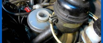
To reduce the force on the brake pedal, a vacuum booster is used, which uses the vacuum in the intake manifold of a running engine. It is located between the pedal pusher and the brake master cylinder and is secured with nuts to a bracket on the front shield in the engine compartment. The amplifier is non-separable; if it fails, it is replaced (on older models the amplifier is from a VAZ-2108; on newer models, a 9-inch amplifier is installed instead of 8). The simplest test: on a car with a non-running engine, press the brake pedal several times and, holding the pedal down, start the engine. If the amplifier is working properly, after starting the engine the pedal should move forward. Remember that failure or insufficient efficiency of the vacuum booster can also be caused by a leak in the hose that takes the vacuum from the intake manifold.
The brake master cylinder is attached to the vacuum booster housing with two studs. Hoses are attached to the fittings in the upper part of the cylinder, through which fluid from the brake reservoir is supplied to the cylinder. The tank has markings for the maximum and minimum liquid levels, and a warning device with a float is mounted in the lid, which closes the contacts when the liquid level drops. Screws at the bottom of the cylinder limit the movement of the pistons. The screws are sealed with copper or aluminum gaskets. A plug is screwed into the front part of the cylinder (along the direction of the car), which serves as a stop for the return spring and is also sealed with a copper or aluminum gasket. The brake pipe fittings are screwed into the holes on the sides of the cylinder: into the front holes - the circuit supplying fluid to the front wheels, into the rear holes - to all wheels.
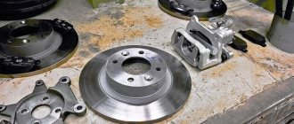
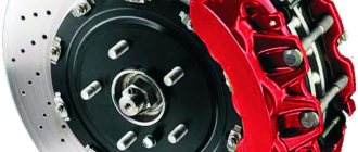
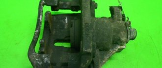
The front wheel brakes are disc brakes with a three-piston floating caliper. The upper piston is driven from one circuit (together with the pistons of the working cylinders of the rear wheels), the two lower ones - from another. The cylinder block is secured in the caliper on two guides and secured with a spring-loaded clamp. Between the cylinder block and the caliper there are pads: the inner one rests on the cylinder pistons, the outer one on the caliper boss. The caliper can move in the pad guide, being pressed against it by two spring-loaded levers. The pad guide is rigidly attached with two bolts to the steering knuckle. The bolts are secured against unscrewing by the edges of the protective casing (they are bent at the edge of the bolts after tightening).
Brake discs are cast iron. The minimum disc thickness during wear is 9.5 mm, the maximum permissible runout (at the largest radius) is 0.15 mm. The minimum permissible thickness of the front brake pads is 1.5 mm.
The rear wheel brakes are drum brakes, with two-piston wheel cylinders and automatic adjustment of the gap between the shoes and the drum. The automatic clearance adjustment device is located in the wheel cylinder and consists of two elastic steel split rings (one for each piston) installed on the pistons with an axial clearance of 1.25–1.65 mm.
The elasticity of the ring is selected in such a way that it does not move along the cylinder mirror from the force of the tension springs of the pads (but only from the force of the pistons). As the pads wear, the pistons move the rings along the cylinders during braking, maintaining a constant design gap between the pads and the drum. If the piston mirrors are damaged due to mechanical impurities in the brake fluid or corrosion, the rings and pistons may “sour” in the cylinder, losing mobility. In this case, it is necessary to replace the cylinders and brake fluid.
Brake drums are aluminum, with cast iron rings (working surface). The nominal inner diameter of the drum is 250 mm. Grooving of drums when worn is allowed. The largest permissible diameter (if worn or after grooving) is 251 mm.
The pressure regulator serves to reduce the braking force on the rear axle, which prevents the car from skidding when braking. It limits the pressure in the rear brake mechanisms depending on the position of the rear part of the body relative to the road: with increasing load on the rear axle, when the traction of the rear wheels with the road improves, the regulator provides more pressure in the wheel cylinders and vice versa, with decreasing load the pressure drops. The regulator is attached with two bolts to a bracket in the right rear part of the body and is driven by an elastic lever attached through a rod to the rear axle beam. As the load on the rear axle of the vehicle increases, the elastic lever is also loaded, transmitting force to the regulator piston. When you press the brake pedal, fluid pressure tends to push the piston outward, which is prevented by the force from the lever. When the system comes into balance, a valve located in the regulator isolates the rear brake cylinders from the main brake cylinder, preventing further increases in braking force on the rear axle. Due to the ovality of the holes in the bracket, the regulator can be rotated, changing its position relative to the lever. To extend the service life of the regulator, 5–6 g of DT-1 (or graphite) lubricant is placed in the protective rubber cap; the axis through which the lever passes and the protruding part of the piston are also covered with it. It is not recommended to disassemble the pressure regulator; if it fails, it is replaced.
The parking brake system is driven mechanically, by cable, to the rear wheels. It consists of a lever, a front cable with a threaded end (with a sleeve and two nuts), a release spring, a rear cable, its guide, two levers and two spacer bars - one (one) for each brake mechanism. The drive is adjusted by moving the nuts on the threaded end of the front cable (after adjustment, the nuts are locked). The full stroke of the lever after adjustment should correspond to a rise of 4–5 teeth along the sector.
Video
Niva brakes
The Niva all-wheel drive off-road vehicle is a modern, fast and comfortable car. This means that all the highest modern requirements for brakes - their efficiency and reliability, for the car’s stability when braking and its ability to maintain the direction of movement (stay in a “corridor” 3.5-3.6 m wide) fully apply to the VAZ-2121 .
On the Niva, as on other VAZ cars, a design with front disc and rear drum brakes was chosen. An all-wheel drive car has a shorter wheelbase and, naturally, a higher center of gravity than a Zhiguli. And at.
When braking, these changed parameters make themselves felt: in the VAZ -2121, the redistribution of load between the axles, unloading the rear axles and overloading the front ones occurs more sharply. And because of this, it was impossible to use the plant’s traditional separate hydraulic brake drive system on the Niva.
The rear circuit alone would not provide sufficiently effective braking; the stopping distance would be too long. Therefore, the Niva used a hydraulic drive scheme in which the front disc brakes would work in any case.
The two working brake cylinders of each front wheel are connected to one cavity of the main brake cylinder and form the primary circuit, and the third cylinders of each front wheel, together with the working cylinders of the rear drum brakes, form the secondary circuit. During tests of the Niva for compliance with OST 37.001.016-70 and the international requirements of the UNECE, a fully loaded vehicle, when any brake circuit was turned off, had a stopping distance from a speed of 80 km/h of only 53 - 60 m with a standard of 90.1 m.
The device of the Chevy Niva traction control system. Possible faults
The Chevrolet Niva braking system, as a product of joint production of two global companies, is well adapted to Russian roads and has a minimum braking distance when driving in the city. What are the features of this system?
The machine has two independent brake systems - a hydraulic working system and a mechanical parking system.
The parking brake is applied when stopping to keep the vehicle in place. It uses brake pads only on the rear wheels and is operated by a lever located in the cabin.
When the lever is placed in the upper position, the brake pads move apart and are pressed tightly against the inner surface of the brake drums, firmly fixing their position.
The movement of the pads is ensured by a cable and drive levers.
- “right front-left rear” contour;
- “left front-right rear” contour;
- master cylinder reservoir;
- hydraulic brake master cylinder;
- vacuum booster;
- brake pedal;
- rear brake pressure regulator;
- parking brake cable;
- rear wheel brake;
- parking brake adjusting tip;
- parking brake lever;
- front wheel brake
In order to increase the reliability and safety of control, the hydraulic brake system of the Chevrolet Niva is built according to a dual-circuit diagonal design.
The first hydraulic drive circuit drives the front right and rear left wheels, and the second drive drives the front left and rear right wheels.
Thus, controllability is maintained in the event of failure of one of the hydraulic drive circuits. The hydraulic braking system includes:
- brake pedal located in the cabin under the driver’s right foot;
- vacuum pedal pressure booster;
- master cylinder with reservoir for filling brake fluid;
- dual-circuit hydraulic drive pipeline;
- working brake cylinders of the rear and front wheels;
- pressure regulator with actuating lever.
Electrical equipment of Chevrolet Niva (electronics)
The pressure of the driver's foot on the brake pedal is increased by a vacuum booster and transmitted to the piston of the master cylinder, which, moving, compresses the brake fluid.
The fluid pressure increases and is transmitted through pipelines to the working cylinders of the front wheels and the brake pressure regulator of the rear wheels.
The pistons of the front calipers and rear working cylinders, under pressure from the brake fluid, extend and press the Chevrolet Nivak brake pads onto the surfaces of the discs and drums, slowing down their rotation.
The pressure regulator (“sorcerer”) is designed to prevent the car from skidding during sudden braking. This is achieved due to the fact that the rear wheels begin to brake after the front ones. The time delay is provided by the regulator lever, which, when the car brakes sharply (the nose drops and the rear rises), pulls the piston in the regulator cylinder and closes the fluid supply channel to the working cylinders of the rear wheels.
In this case, the rear brakes do not work and the wheels spin until the rear of the car drops back. Thus, the “sorcerer” automatically regulates the fluid pressure in the rear cylinder path in inverse proportion to the load on the rear axle. In addition, it increases the braking efficiency of an empty vehicle when the load on the front axle is higher than on the rear.
If the car does not brake effectively, skids or is pulled to the side, then this is a reason to check and adjust the regulator.
Also interesting: Niva engine tuning
This work must be carried out at every maintenance and after repair of the rear suspension.
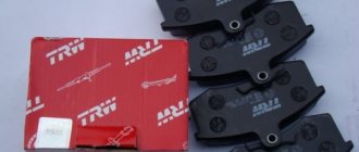
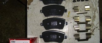
The front wheels of the Niva Chevrolet use disc brakes, and the rear wheels use drum brakes. Accordingly, the pads on them are different. Pads are the main working part of the brakes, which carry the most load and wear out the fastest. If the car is used intensively, the condition of the pads should be checked at least once every six months. Today there are many different domestic and foreign manufacturers of pads for Niva-Chevrolet cars.
Chevrolet Niva tow bar. What is it and how to install it?
They differ in price, material, service life. The so-called “Kevlar” pads from the Japanese company NIBK are considered the most effective and “cool”. They are made using modern nanotechnology from a compound that is equally effective in various operating modes. The advantages of this pad model include:
- low heating temperature during braking;
- do not require heating in winter;
- they do not creak or squeal even during sudden braking;
- have a longer service life compared to other models.
The only disadvantage of these pads is the high cost, but the price corresponds to the quality.
If you need information about replacing front pads, this is the place for you.
Reviews from car enthusiasts about the brake system on the Chevrolet Niva show that it is generally quite reliable and effective, fully consistent with the class of SUV cars.
The advantage is ease of control, ease of maintenance, adjustment and replacement of parts.
The disadvantages are due to the use of a pressure regulator, the operation of which in some cases can manifest itself in the form of uneven braking, the appearance of vibration when braking at certain speeds, and an increase in braking distance.
Effective brakes on the Chevrolet Niva, as the main condition for the safety and controllability of the car, help maintain the high popularity of this model for many years.
Finally, it has happened; from now on, the Chevrolet Niva includes a safety package - front airbags and ABS.
On the one hand, this won’t surprise anyone now, but for a domestic car, which the Chevy Niva essentially is, this is already something. Well, now it's up to the engine.
The main thing is that this does not greatly affect the price, because even now it is no longer small...
General information
The automatic brake release system (ABS system) is designed to increase vehicle stability under heavy braking conditions or when driving in poor road conditions. This is ensured by the fact that the pressure in the brake circuit is regulated depending on the wheel speed recorded by the sensors.
System composition:
- Actuator
- Front speed sensors
- Diagnostic connector (DLC1)
- Control block
- ABS system service indicator lamp
- Speed sensor rotors
- Rear speed sensors
- Diagnostic connector (DLC1)
- Brake light switch
- ABS motor relay
- Solenoid valve traction relay
October 10, 2012
Our cheat sheet is addressed to such “crazy people”
The cost of a set of front pads is 370–950 rubles, rear pads are 650–1200 rubles. The cost of a set of front pads is 370–950 rubles, rear pads are 650–1200 rubles. The cost of a set of front pads is 370–950 rubles, rear pads are 650–1200 rubles.
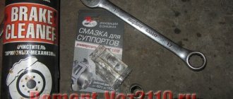
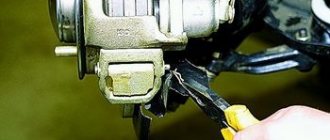
We hang and remove the front wheel. It is advisable to clean the surfaces and treat the joints of the axle and cotter pin with a penetrating lubricant such as WD-40.
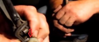
Using pliers, remove the cotter pin of the lower clamping lever axis. Using pliers, remove the cotter pin of the lower clamping lever axis. Using pliers, remove the cotter pin of the lower clamping lever axis. Using a drift, we touch the axis of the clamping lever... Using a drift, we touch the axis of the clamping lever... Using a drift, we touch the axis of the clamping lever... ...and, holding the lever, we take out the axis with pliers.
...and, holding the lever, use pliers to remove the axle...and, holding the lever, use pliers to remove the axle. We remove the clamping lever. We remove the two clamping lever springs from the shoe guide so as not to lose them. We remove the two clamping lever springs from the shoe guide so as not to lose them. We remove the two clamping lever springs from the shoe guide so as not to lose them.
Using a screwdriver, we lift the brake caliper... Using a screwdriver, we lift the brake caliper... Using a screwdriver, we lift the brake caliper... ...and place it with the cylinder block on the steering knuckle....and place it with the cylinder block on the steering knuckle....and place it with the cylinder block on the steering knuckle.
Remove the brake pads from the guide. Before installing new ones, it is necessary to move the pistons as far inside the cylinders as possible. We remove the brake pads from the guide. Before installing new ones, it is necessary to move the pistons as far inside the cylinders as possible. We remove the brake pads from the guide.
Before installing new ones, it is necessary to move the pistons as far inside the cylinders as possible. Using sliding pliers (or a pipe wrench), press the pistons into the cylinders. You can recess the pistons into the cylinders in another way. To do this, we insert the outer block into the guide and, having installed the caliper in place... Using sliding pliers (or a pipe wrench), we press the pistons into the cylinders.
You can recess the pistons into the cylinders in another way. To do this, we insert the outer block into the guide and, having installed the caliper in place... Using sliding pliers (or a pipe wrench), we press the pistons into the cylinders. You can recess the pistons into the cylinders in another way. To do this, insert the outer block into the guide and, having installed the caliper in place... ...using a mounting spatula, press the pistons into the cylinders.
We carry out further assembly of the unit in the reverse order. To make it easier to install the axis of the pressure lever, use a file......using a mounting blade, press the pistons into the cylinders. We carry out further assembly of the unit in the reverse order. To make it easier to install the axis of the pressure lever, use a file......using a mounting blade, press the pistons into the cylinders.
We carry out further assembly of the unit in the reverse order. To make it easier to install the clamping lever axis, use a file... ...or sand the end of the axle like this......or use sandpaper to grind the end of the axle like this......or use sandpaper to grind the end of the axle so... ...to form a cone. Before installation, lubricate the axis of the clamping lever with graphite grease.
...to make a cone. Before installation, lubricate the axis of the clamping lever with graphite grease...to form a cone. Before installation, lubricate the axis of the clamping lever with graphite grease. Pressing the lever, insert the axle. After installing the brake pads, you must press the brake pedal several times so that the cylinder pistons move the pads to the brake disc.
Also interesting: Rear disc brakes on the Niva
Pressing the lever, insert the axle. After installing the brake pads, you must press the brake pedal several times so that the cylinder pistons move the pads to the brake disc. Press the lever and insert the axle. After installing the brake pads, you must press the brake pedal several times so that the cylinder pistons move the pads to the brake disc.
Electrical diagram of VAZ 2121 Niva
Electrical diagram of VAZ 2121 Niva
1 — side direction indicators; 2 — front lights; 3 — headlights; 4 — electric motors for headlight cleaners; 5 — sound signals; 6 — relay for turning on headlight cleaners and washer; 7 — relay for turning on low beam headlights; 8 — relay for turning on high beam headlights ;9 - windshield washer electric motor;10 - insufficient brake fluid level sensor;11 - portable lamp socket;12 - oil pressure warning lamp sensor;13 - oil pressure indicator sensor;14 - coolant temperature indicator sensor;15 - ignition distributor ;16 - spark plugs;17 - windshield wiper motor;18 - ignition coil;19 - generator;20 - carburetor shut-off valve;21 - starter;22 - headlight washer motor;23 - voltage regulator;24 - battery charge warning lamp relay; 25 — battery; 26 — windshield wiper relay; 27 — additional fuse block; 28 — main fuse block; 29 — parking brake warning lamp switch; 30 — differential lock warning lamp switch; 31 — reverse light switch; 32 — warning lamp switch carburetor air damper; 33 — brake light switch; 34 — heater electric motor; 35 — relay-breaker for turn signals and hazard warning lights; 36 — additional resistor for the heater electric motor; 37 — instrument lighting switch; 38 — headlight switch; 39 — indicator switch turn;40 — sound signal switch;41 — windshield wiper switch;42 — windshield washer switch;43 — ignition switch;44 — exterior lighting switch;45 — heater switch;46 — headlight wiper and washer switch;47 — cigarette lighter;41 — hazard warning switch; 49 — lamp switches located in the door pillars; 50 — oil pressure indicator with an insufficient pressure warning lamp; 51 — fuel level indicator with a fuel reserve warning lamp; 52 — tachometer; 53 — parking brake warning lamp; 54 — control lamp battery charge lamp; 55 — carburetor air damper warning lamp; 56 — speedometer; 57 — exterior lighting warning lamp; 58 — turn signal warning lamp; 59 — headlight high beam warning lamp; 60 — parking brake warning lamp breaker relay; 61 — brake fluid level warning lamp; 62 — differential lock warning lamp; 63 — coolant temperature indicator; 64 — lampshades; 65 — fuel level and reserve indicator sensor; 66 — rear lights;
67 — license plate lights.
Front brake mechanisms from 2112 on Niva 2121, VAZ 2131
But first, let's figure out why they are better. After all, classic brakes have 2 cylinders, so their efficiency should be higher. But do not forget that it was the “classic” brakes that were invented 40 years ago and have never undergone factory modifications. Of course, the floating caliper in the front-wheel drive VAZ family is also not the height of perfection and, probably, it would be more correct to install 6-piston calipers from such eminent manufacturers as Brembo, JBT, Wilwood, etc., but the budget for such alterations can be up to 50% of the cost of the new one is 2107. And the brakes from 2112 are ventilated and have a 260 mm brake disc. Therefore, their advantages are that in extreme driving conditions it will be more difficult to heat the brake fluid to a boil, and also due to the enlarged brake disc, the braking force arm will be greater, in other words, you need to put less effort on the brake pads to stop the wheel, but how It is known that a wheel slows down a car.
GAZ 2705 | Pressure Regulator Adjustment | Gazelle
After the first 2500 km and during TO-2, and also if the rear wheels of an equipped vehicle lock up earlier than the front wheels or much later when braking on a dry hard surface, you should make sure that the regulator is adjusted correctly.
The regulator should be adjusted in the following order:
| Rice. 8.4. Pressure regulator: C = 28-32 mm (for buses), 13-17 mm (for vans); 1—press lever; 2 - pin; 3 — fixing bolt; 4 — axis of the pressure lever; 5 - nut; 6 - axis; 7 — body; 8 and 9 — regulator brackets; 10 - lock nut; 11 — adjusting bolt; 12 — load spring; 13 - spring; 14 — piston sleeve; 15 — control cone; 16 — pressure spring; 17 - ball; 18 — thrust bracket; 19 — return spring; 20 - bushing; 21 - piston; 22 — protective cover; 23 — bridge bracket; 24 - stand; 25 - spring washer |
— disconnect the lower end of the regulator strut 24 from bracket 23 (see Fig. 8.4) on the rear axle by unscrewing the axle nut 5 to do this; - unscrew locknut 10 a few turns and, rotating adjusting bolt 11, set distance C: for GAZ-2705 and GAZ-2705 “Combi” - 13-17 mm; for buses - 28-32 mm between axle 6 and hole in bracket 23;
— tighten the locknut, holding the adjusting bolt from turning;
— secure the lower end of the rack to the rear axle bracket.
It is necessary to check the correct adjustment of the pressure regulator by braking until the wheels lock on a horizontal section of the road with a hard, dry surface at a speed of 50–60 km/h. If the pressure regulator is in working order and correctly adjusted, during effective braking there should be some advance in the locking of the front wheels relative to the rear ones. If the rear wheels lock before the front wheels, then, after first unscrewing the lock nut 10, unscrew the adjusting bolt 11 by half a turn and lock it again. If the front wheels lock much earlier than the rear wheels, you should tighten the adjusting bolt half a turn.
After performing the above operations, check the adjustment of the regulator again by braking on the road.
It should be remembered that if the rear wheels are blocked ahead of time, the car may skid, and if the front brakes are blocked much earlier than the rear ones, then the car may lose control, especially when driving on a slippery road.
How to adjust the sorcerer on a Niva Chevrolet?
The algorithm for adjusting the sorcerer is as follows:
- First of all, the car should be installed on an inspection hole or overpass.
- Next, you need to set the suspension to the working position. To do this, using our own weight, we pump the rear suspension several times. By the way, the Chevrolet Niva’s equipment should be standard, without any extra cargo. Only a spare wheel and a set of keys.
- We move into the pit and use a key to loosen the fastening of the bracket with the sorcerer.
- We move the bracket so that the gap between the lever and the lever spring is within 2 mm. We determine the gap with any wire of suitable diameter.
- We tighten the fastening bolts and conduct a small crash test.
We accelerate the car to a speed within 30-40 km/h and press the brake relatively sharply (I mean the brake pedal), while the observer (your core fan, a neighbor in the garage or just a drinking buddy, but what's the difference?) should visually record the locking of the rear wheels slightly later than the front ones.
If this does not happen, we conclude that the adjustment was not performed entirely correctly, which means we repeat the operation of adjusting the sorcerer on the Chevrolet Niva one more time, preferably before a snack.
A few more words about adjustment. If the rear wheels lock too late, the gap should be reduced. But if the rear ones lock too quickly, almost at the same level as the front ones, or before them, then the gap should be increased.
Basically everything. This completes the adjustment of the sorcerer.