Functional features of VAZ-2109 valve guides
Experts say that the engine valve guide is a necessary part for every vehicle. Its main function is to provide precise direction in the movement of engine valves when they close and open, which is characterized as reciprocating. These guides form a friction “sleeve-valve” pair, which determines the consumption of engine oil. This part also ensures a tight fit of the valve plate to its seat.
The need to replace bushings
Wear can be determined by several indirect signs; there are also cases when it is necessary to change bushings:
- engine oil penetrates into the combustion chamber , due to this its consumption increases and grayish smoke is formed from the exhaust pipe;
- a characteristic tapping sound is heard from the side of the block head;
- when completely replacing a set of valves;
- overhaul of the block head.
Pressing tool
Why can cartridges fail?
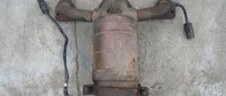
The main reason for failure of guide bushings is their wear. As a result, the consumption of lubricating fluid increases, since the backlash of parts leads to rapid failure of the valve stem seal and oil leaks into the combustion chamber. As a result, there is the formation of carbon deposits, a violation of the temperature regime of the engine, an increase in the toxicity of exhaust gases and breakdown of the catalyst (if the car has one).
This is interesting: Engines from German and American manufacturers
Worn valve bushings VAZ 2106
Timely replacement of engine oil and proper operation of the vehicle’s internal combustion engine allows you to extend the life of the bushings and change them every 180–200 thousand kilometers. However, due to valve clearances and engine oil non-compliance with recommended standards, lateral wear of the bushings and a decrease in valve mobility along the axis of the rod may occur due to an increase in the radial load on it. For this reason, after changing the valve stem seals, the gap in the guide bushings must be adjusted. If the gap is too large and play is detected, the bushings must be changed.
Why do you need a guide bushing?
The guide bushing can quite rightly be considered the main element on which the resource and proper operation of the “seat - valve plate” tandem depends. The material from which the part is made and its design itself are primarily aimed at working under conditions of high speeds of the valve stem fixed in it, constant high-temperature loads and the almost complete absence of lubrication in the valve-bushing pair.
Causes and consequences of deformation
The described conditions lead to the fact that during engine operation, the valve guide bushing also wears out, which is why, over time, its alignment with the valve stem may be disrupted. Subsequently, the part breaks even more and the valve begins to “walk” and does not fit tightly to its seat, and this, in turn, leads to the chamfer of the seat breaking over time. As a consequence, you can get a burnout of the valve and have to replace the seat.
Appearance of bronze guide bushings for VAZ 2108–2109 models
Also, due to the “walking” of the valve in a broken guide, the oil seals can quickly become unusable. They simply will not be able to hold oil with increased angular displacement of the valve stem. The result will be oil getting into the engine, and if you also take into account that more oil will pass through the broken bushing than usual, then the situation will not be pleasant. Carbon deposits on valves and other parts around the combustion chamber will increase, the level of harmful exhaust emissions will increase, and you may end up with a prematurely failed catalytic converter. And simply replacing the valve stem seals is not enough, as the problem will soon return again.
Why you shouldn't neglect checking
When repairing an engine, it is better to pay special attention to its head. Often it is this part of the engine that is to blame for the fact that the level of compression in the cylinders is far from the desired level. When repairing cylinder heads, motorists sometimes limit themselves to only grinding the valves to their seats, believing that there is nothing particularly wearable in all-metal bushings. At the same time, checking how large the gap between the part and its valve is will be completely worthwhile. When the obtained clearance figures go beyond those recommended by the car manufacturer, then no amount of grinding in the valves or replacing the valve stem seals will protect against problems in the future.
Materials used to make bushings
For the manufacture of bushings, materials with good wear resistance and thermal conductivity are used. Among these you can find:
- special cast iron alloys;
- bronze;
- brass;
- metal ceramics.
In terms of thermal conductivity and cost, brass, along with bronze, are among the leaders, so the vast majority of bushings are made from alloys of these metals.
Nuances to consider
Most bushings have a special support collar on the outside, designed to ensure proper fixation of the part vertically in the cylinder head. If the part is smooth, then installation is carried out using a special mandrel.
For intake valves, the guide bushings should not protrude so as not to increase the aerodynamic drag of the intake channel. Exhaust valve bushings are designed to “hide” the valve stem as much as possible to protect the latter from high temperatures and better heat dissipation.
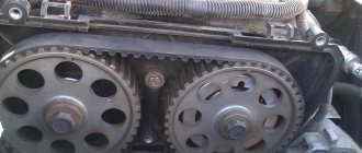
Appearance and location of the valve guide in the cylinder head
The manufacturing precision of the bushings is very high. This is necessary to obtain the most accurate alignment and the best fit of the valve plate and seat during engine operation. The outside of the body of the part that is to be pressed into the cylinder head must be processed as cleanly as possible; there should be no scratches or marks on it. This ensures optimal heat removal from this accessory to the block head.
Video: review of valve guides for VAZ 2108–2109
How to determine if the guide bushings are worn out
Oil also gets into the cylinders due to malfunction of parts of the cylinder-piston group. To exclude this cause, it is necessary to measure the compression. This will prevent piston ring failure.
Inspect the spark plugs. The most fouled spark plug indicates problems in that cylinder. Next, we inspect the motor for wear on the guides in the following order:
- Unscrew the nuts securing the valve cover to the cylinder head and remove it.
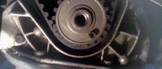
- Loosen the chain and, aligning the marks, unscrew and remove the camshaft gear.
- Gradually and one by one, unscrew the camshaft bed and remove it.
- Remove the rocker arms, unlock the valve springs of the cylinder in which the spark plug is most covered with soot.
- Carefully remove the oil seal and rock the valve sideways, moving it up and down. If there is lateral play during movement, the bushing needs to be replaced.
In operating condition, the gap between the valve and the guide is minimal and does not allow the valve to move in the horizontal direction (only up or down). Therefore, any sideways wobble means wear on the bushing.
Before buying new guides, it is advisable to remove the valves and bring them to the store. And when choosing, be sure to try their fit on the valve stem.
The guide bushing on the valve stem should move easily, but should not be loose.
This is necessary so that in the future you do not have to go to the store again if the bushings do not fit for some reason.
The procedure for replacing guide valves on a VAZ 2106
The whole procedure is divided into several stages:
- Preparation of tools.
- Partial disassembly of the engine, namely, removal of the cylinder head.
- Selection and purchase of new parts.
- Dismantling worn elements and pressing in new ones.
- Reassembling and starting the engine.
The first step is to disconnect the battery from the on-board network
Advice. It is worth following exactly this sequence of actions - first disassembling the engine, and then purchasing spare parts. The dissection will show you exactly what parts you need. If you recently changed the valves (5-10 thousand km ago), then you need to pull them out to try them on with the new bushings in the store. The old valve group will have to be replaced.
Preparing the necessary tools
To disassemble and replace the guides, you will need:
- standard set of open-end and ring wrenches;
- a set of sockets with a powerful wrench and ratchet;
- a torque wrench for tightening the cylinder head bolts and camshaft nuts during assembly;
- screwdrivers, pliers;
- 36 mm wrench for manual rotation of the crankshaft;
- mount;
- puller for unlocking valves;
- heavy hammer;
- mandrel for knocking out and pressing in bushings;
- 8.025 mm reamer with knob;
- container and hose for emptying the cooling system;
- rags.
You can’t do without a ratchet wrench and sockets when removing the cylinder head.
We recommend: Design and principle of operation of the fuel pump
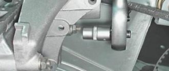
The mandrel for working with guides is a steel rod, the end of which is machined to fit the inner diameter of the bushing. The second part of the mandrel is a nozzle for pressing, the size of which is adjusted to the wide outer part of the part (the so-called cap), since it is impossible to hit the end. The kit can be ordered from a turner or purchased ready-made; it is inexpensive.
The mandrel for knocking out and seating bushings can be machined according to the drawing
Advice. In the process of replacing the guides, you will have to re-grind the valves, or even trim the seats. This work requires a special tool and appropriate skills, so it is better to entrust the operation to a master. In addition, the purchase of devices for cutting and lapping will reduce to zero all the benefits of repairing the cylinder head with your own hands.
This is a scan used on the cylinder head of VAZ 2101-07 cars
A reamer is a bench tool designed for precise adjustment of the internal diameters of holes. In this case, it is necessary to rotate the inner part of the bushing under the valve stem with minimal clearance.
Removing the cylinder head and old bushings
This stage is the most labor-intensive and time-consuming; it begins with disconnecting the battery and emptying the water jacket of the engine (there is no need to drain the liquid from the radiator). Perform further operations in this order:
- Disconnect the starter cable, gasoline hose and accelerator drive, then remove the air filter housing and carburetor.
- Unscrew the valve cover and align the notch on the crankshaft pulley with the long notch on the block. Disconnect the wires from the spark plugs and remove the distributor, remembering the position of the slider. Remove the wire from the temperature sensor.
- Loosen the chain by unscrewing the tensioner, then unlock the camshaft gear nut and unscrew it. Remove the gear and secure the chain so that it does not fall inside the block. Unscrew the nuts securing the camshaft bed and remove it from the studs.
- Disconnect all cooling system pipes and exhaust pipe “pants” from the cylinder head.
- Loosen the 11 cylinder head bolts in random order and remove them. Using both hands, lift the cylinder head and remove it along with the manifolds.
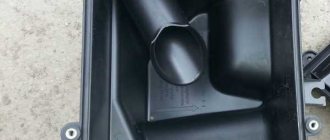
Removing the filter housing
Advice. Immediately after dismantling the head, clean the block of the old gasket and cover it with a clean cloth so that dirt does not accidentally get inside the cylinders.
Place the removed cylinder head conveniently on the table and remove the springs with the rocker arms (it is advisable not to mix them up), then use a puller to unlock the valves and pull them out. At the same time, do not lose the “crackers” - small half-cylinders inserted into the slot of the rod. Then turn the head over with the combustion chambers facing up, place wooden blocks along the edges and knock out all the bushings with a mandrel. Strike with medium force, clearly and accurately. At the end, clean and thoroughly wipe the entire cylinder head from carbon deposits and deposits.
The carburetor must be removed from the manifold so that it does not interfere
Recommendation. Take this opportunity to inspect the disassembled engine for other faults in order to eliminate them immediately. Involve a mechanic - a motor mechanic with a device - a bore gauge, so that he can check the output in the cylinders and advise you on all issues. This is important if you are disassembling the VAZ 2106 power unit for the first time.
It is important to align the marks before disassembling
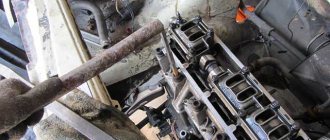
Photo instructions for removing the cylinder head
To get to the camshaft, you need to dismantle the valve cover. Removing the distributor. The camshaft gear must be unscrewed and removed without disturbing the position of the marks. After unlocking, the springs can be easily removed. The cylinder head must be carefully removed with both hands. To remove the valves, you need to use a puller to unlock the cylinder head springs in disassembled form. Removing the camshaft housing. Disconnecting the wire from the temperature sensor From the cylinder head, you need to remove all the pipes of the cooling system. The bushing is knocked out with a hammer through a mandrel. Removing the rocker arm springs (rockers).
How to dismantle the cylinder head of a VAZ 2106 - video
Selection of new parts
Guide bushings for the "six" engine can be purchased in two versions - cast iron or bronze. When choosing, you should adhere to the following recommendations:
- If you have a normal driving style and are not into car tuning, there is no point in installing bronze products. Buy inexpensive cast iron guides and they will last quite a long time.
- It is better to install bronze parts together with lightweight chrome-plated valves (for example, from the AMP brand).
- Considering the price of cast iron products and your first experience of replacing them, it is recommended to purchase 2 sets of parts. The reason is the fragility of the material, which can accidentally crack if handled improperly.
- Select the bushings in such a way that the valves are inserted into them with difficulty or do not fit at all. Do not take products with incorrect holes where the rod fits freely.
- If after disassembly you find that one or more bushings are spinning or dangling in the cylinder head sockets, you need to select repair products. Their outer diameter is 0.05-0.1 mm larger than the standard one, which will allow such parts to fit into broken holes in the cylinder head. Here it is worth using measuring instruments - a micrometer and a bore gauge.
Advice. Do not listen to assurances that bronze bushings resist wear better than cast iron ones, this is not true. Cast iron is much harder than most metals, including bronze, it just transfers heat less well. Hence the conclusion: both parts are good, but they must be used for their intended purpose.
It is also worth purchasing a new valve group (if it has not been changed recently), gaskets for the cylinder head and various pipes, and 1-2 liters of antifreeze for topping up. Buy the rest of the parts based on the results of the previous troubleshooting.
Fitting bushings and reassembling
To press the guides into the sockets, turn the cylinder head over with the combustion chambers facing down. Then place the retaining rings on the elements, pulling them from the top end. If you start putting the ring on from the bottom, be sure to leave deep grooves on the surface where oil can subsequently leak.
Important! Before planting, lubricate the outer surface of the parts with a thin layer of engine oil.
The new bushing is driven all the way through the spacer
We recommend: How to check current leakage on a car with a multimeter
To press fit, insert the end of the first bushing into the hole, put the nozzle on the mandrel and attach it to the wide part of the part. Using precise blows of a hammer on the spacer, drive the bushing in until it stops, which is characterized by a change in the sound of the blows (a slight ringing will appear). Hit with medium force so as not to crack the cast iron. Repeat the action with all the elements, and if one of them breaks, take a spare one.
Reference. You can often hear recommendations that the cylinder head should be heated in a bucket of water, and the bushings should be placed in the freezer before driving. These activities really make pressing easier, but take a lot of time. Any knowledgeable mechanic will tell you that fitting cast iron into an aluminum alloy with an interference fit of 0.04-0.06 mm can be easily done without any heating.
The bushing holes should be driven through with a reamer
After pressing is completed, you need to drive the inner diameter of the bushings with a reamer so that the valve stem slides in it with minimal clearance. The operation is performed as follows: secure the tetrahedral end of the reamer in the driver, lubricate the working part with engine oil, insert it into the hole and rotate clockwise. The tool must go along the entire length of the part. Now all that remains is to install and grind the valves, which is recommended to be entrusted to a specialist. Then reassemble the engine in reverse order, but taking into account the key points:
- If you want to improve the tightness of the gasket between the head and the block, treat it with a thin layer of graphite lubricant. High temperature sealants cannot be used.
- Tighten the 10 main cylinder head mounting bolts with a torque wrench in 2 steps in the sequence shown in the diagram. The first time tighten them to a torque of 41 Nm, the second time - 118 Nm. The eleventh bolt of a smaller size is tightened at a time with a torque of 39 Nm.
- The camshaft bed is also pulled according to the scheme, maintaining a torque of 22 Nm.
- The gear and chain must be installed so that the round mark on the sprocket coincides with the boss on the camshaft housing. You aligned the marks on the crankshaft before disassembling, check them.
- Do not forget to adjust the gaps between the rocker arms of the valve group and the camshaft cams (its value should be 0.15 mm).
- When installing the distributor, restore the original position of the slider so as not to disable the ignition.
Cylinder head bolt tightening diagram
Advice from experienced people. After tightening the cylinder head bolts, old craftsmen often let the engine sit for 12-24 hours, and then tightened the head again. If you have time, follow this recommendation; in a day you will see for yourself that the nodes have “settled” and the bolts have loosened a little.
Procedure for tightening the camshaft nuts
After completing assembly and filling with antifreeze, start the engine, warm it up and rotate the distributor housing to set the optimal ignition timing.
Aligning the round mark on the gear with the boss on the body
Replacement process
As mentioned above, a special attachment is required to remove and install the guides. Let's look at what it is and how to use it.
Description of the tutorial
The mandrel for removing and installing the guide consists of two parts. The first part is a rod of a certain length, machined on a lathe and having different diameters in certain places. The largest diameter of the rod occupies its main length and is 18 mm. The rod is held by hand by this part, and it limits the rod from slipping to the other side when removing the bushing, which will protect the surface of the block head from being hit with a hammer. The diameter of the second part of the rod is equal to the diameter of the sleeve. The length of this part is equal to the depth of the hole in which the sleeve is located. The third part of the stem is the shortest - its diameter corresponds to the internal diameter of the valve stem (the diameter of the inner surface of the guide). Its purpose is to ensure that when knocking out the bushing, the direction of the rod strictly corresponds to the direction of the bushing and does not create a distortion of the rod when hitting it with a hammer.
This is interesting: Basics of power steering. Causes of loss of performance
The second part of the rod is similar to a socket head. It is distinguished from a socket head by the absence of edges inside (a cylindrical hole with a diameter and length equal to the diameter and length of the upper part of the guide). In the upper part of the head there is a hole with a diameter equal to the inner diameter of the sleeve and the outer size of the rod on the working side. As can be seen from the description of the mandrel, finding a replacement for it using available materials is not so difficult. To do this, at a minimum, you will need a cylindrical rod of a convenient length, the diameter of which on one side is equal to the outer diameter of the sleeve. As an attachment, you can use an old oil pump rod from a VAZ, after grinding off the gear.
To install the guide in place, use a socket of the appropriate diameter or a suitable hollow tube. Further in the text the terms “mandrel”, “rod”, “head” will be used, implying both a special mandrel and suitable available means.
The process of removing a worn guide and installing a new one
To remove the bushing, turn the cylinder head over with the working part facing up. Next, take the stem, insert it into the valve hole and carefully press it out with a hammer.
In this process, the accuracy of the blow is important. If you hit the surface of the cylinder head with a hammer, this will disrupt the plane of the cylinder head. To knock out the bushing, the blow must be strong, and for this it is better to use a heavy hammer. To install a new bushing, place the cylinder head on the surface in the position in which it is placed on the engine. Then take the new bushing, coat the outer surface with oil and install it in the desired hole.
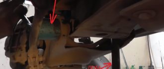
Next, put the head on it and insert the rod. Gently hitting the top of the rod with a hammer, press the bushing guide into place. When installing, pay attention that the selected means do not touch the top of the oil seal seat (marked with arrow 1), since upon impact the seat will be deformed or a piece will break off from it. The head should rest against the base of the oil seal seat (marked with arrow 2).
There are no problems with removing and installing the guide bushing. This is a simple procedure that requires certain knowledge, accuracy and precision when working.
How to replace valve bushings on a VAZ 2106
- Open access to the valve bushings by turning the two outer pins, which prevent the installation of the mandrel. They are loosened by screwing four nuts onto them in pairs. You can resort to a special pin driver.
The VAZ 2106 cylinder head studs are unscrewed to access the valves
- The guide bushing is easily pressed out by hitting the inserted mandrel with a hammer. Before you begin removing the old bushing, you need to turn the cylinder head over.
Pressing the VAZ 2106 guide bushing out of the socket using a special tool
- The part is installed in the saddle, then pressed into the plane of the cylinder head with a hammer and a mandrel. Retaining rings are put on the bushings and in this state they are pressed into place. The intake valve bushings on the VAZ 2106 are slightly shorter than the exhaust valve bushings. The inside is covered with grooves that lubricate the valves. The length of the grooves differs between intake and exhaust valves: in the first case they go only to half of the seat, in the second - to its bottom.
Pressing in new guide bushings VAZ 2106
- Once the installation of the bushings is complete, their holes are rotated, and their diameters differ.
The holes in the VAZ 2106 guide bushings are deployed after installation
How to correctly replace VAZ-2109 valve guides
Of course, if you really want to replace the elements that serve to guide the movement of the engine bushing, you can do it yourself in a garage. But such a procedure can cause some difficulties. This is due to the fact that the bushing itself is pressed tightly in order to prevent the appearance of a gap through which engine oil can enter the combustion chamber.
To carry out the procedure for replacing guide elements, you will need tools (every car enthusiast usually has them in the garage):
- puller/mandrel for pressing out;
- presser;
- 8.03 mm reamer (a special long drill with which the hole is brought to the desired size).
It is also advisable to prepare the coolant. All these tools will be needed, since before replacing the guide element you will have to remove the bushings themselves.
On the VAZ-2109, the replacement procedure is carried out in the following sequence:
- The first stage is preparing the engine for removing the valve bushings from it:
- the valve cover is removed;
- the bolts that secure the block head are unscrewed (there should be ten of them);
- the cylinder head is removed;
- the camshaft is removed from it;
- the studs are unscrewed (primarily the end ones).
- The second stage, cleaning the cylinder head, should be done on a workbench using a solvent or diesel fuel.
- The third stage is pressing out or knocking out the bushings:
- the mandrel is placed on this element from the side of the combustion chamber;
- the head heats up to a temperature of 100-120 degrees;
- use a hammer to knock out each of the bushings (the blows should be relatively light);
- the areas from under the knocked-out parts are washed with gasoline using a rag or a rag made of soft material;
- After washing, the seats are blown with compressed air.
- The fourth stage is the replacement of the engine valve guides with the subsequent assembly of the entire mechanism:
- the block head heats up;
- a repair kit of new bushings is pre-cooled in a regular freezer;
- mounting holes for bushings are processed using a reamer;
- New guide elements are placed in the machined holes.
- The fifth stage is pressing, which is carried out by hammering using a mandrel.
Mechanism design
During operation of the valve mechanism, the movement of the valves occurs in a limited space. The direction for movement is set using the coaxiality of the hole in which the axis of the rod and the inlet/outlet “walks”. The material for the rod is selected to be as wear-resistant as possible.
The steel is alloyed with large amounts of chromium and nickel. The valve guides mating with the stem are made of less durable material, often copper-containing alloys. This is due to the fact that a repair kit of such bushings will cost less to maintain than a complete replacement of valves with a worn stem. Also, the steel-brass pair works much better with frictional mating.
Replacing bushings
There is practically no gap between the hole and the valve. This and the presence of seals on the rod help prevent oil from entering the combustion chamber. But due to the fact that the valves operate under aggressive conditions and with intense movement, the bushings wear out and they have to be changed periodically. If they were not included in the structure, then the entire head of the blocks would have to be replaced after they were worn out in the holes along which the rod runs.
Replacing valve guides
Extraction
- Here it is strongly recommended to warm up the cylinder head to about 100 degrees Celsius before the procedure. The aluminum from which the cylinder head is made has a higher expansion coefficient than the material of the guide sleeve. Due to heating, the tension of the bushing-cylinder head connection is significantly reduced and the guides can be easily pressed out without damaging the seat with light blows of a hammer or sledgehammer.
- A special drift tool (mandrel) is used for extraction. Despite its highly specialized nature and high cost, this tool makes it possible to press out exactly along the axis of the guide sleeve. For such procedures, experienced car mechanics often acquire pneumatic hammers and special drift attachments for them.
Tool for pressing out and pressing in guide bushings
- It happens that a part does not want to come out. In such cases, it is drilled out. And it’s better to use a drilling machine. If you use a conventional drill for work, there is a risk of damaging the socket and creating a misalignment. You may not have to completely drill it out. With thin walls it will be much easier to knock it out.
- The inner surface of the seat after removal should be as smooth as possible and perfectly clean. There should be no scratches, roughness or other, even the slightest, defects. To obtain a similar result, it must be further processed after pressing.
Pressing video
Installing new
- Before installing new spare parts, you need to determine the value of the actual tension. To do this, the diameter of the seat in the cylinder head and the diameter of the bushing are measured. The difference between the first and second should not exceed 0.03–0.05 mm.
- If the socket is noticeably larger than the bushing chosen for it, then you should look for a part with a larger diameter. If the diameter of the socket is insufficient, then you can use the services of a drilling machine to increase it.
- Before pressing in new bushings, the cylinder head must also be heated. But it is generally recommended to cool new spare parts in liquid nitrogen, which will greatly reduce their outer diameter and make it easier to enter into the housings that have expanded from heating, and will also reduce the risk of damage during pressing.
- But since not everyone has liquid nitrogen in their garage, you can first place the new bushings in the freezer. Again, if the latter is available in the accessibility zone. For simplicity, we can take as the required temperature difference between the cylinder head and the guide bushing equal to 150 degrees Celsius. Even when pressing bushings, it is recommended to lubricate the rubbing surfaces with liquid machine oil, especially if the parts have not been heated/cooled.
- The pressing process itself follows the same scenario as pressing out. As a tool, a mandrel and a hammer (or an air hammer with an attachment). Next, using a series of successive blows, we hammer the part into the seat.
Video on pressing
Causes of parts failure and their consequences
A characteristic feature of the guide elements is that they do not fail at once, but wear out gradually. The lifespan of parts on budget cars ranges from 180 to 300 thousand km, and on more expensive foreign cars it can reach 1 million km. The wear process is influenced by several factors that can accelerate it:
- the quality of the motor oil used and the timeliness of its replacement;
- temperature conditions of the power unit, the more often the engine overheats, the faster the rubbing surfaces wear out;
- the quality of the fuel and combustible mixture, whose vapors penetrate into any leaks and contribute to the process of slow destruction of parts.
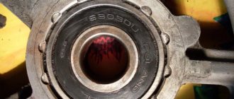
Carbon deposits on the rod destroy the bushing quite quickly
Note. The working life of all elements of the gas distribution mechanism is also affected by the serviceability of the power supply and ignition system. When, as a result of a malfunction, pops occur in the fuel or exhaust manifold, the lubricant between the valve-bushing pair is washed off with unburned gasoline, which is why the mechanism runs “dry” for several seconds.
A worn part is characterized by a “broken” internal hole, as a result of which the valve stem begins to move too freely in it, and then play appears. The rod warps during operation, and the plate does not fit well with the seat, the tightness of the interface is gradually lost. Gases escape from the combustion chamber into the mechanism, and oil enters from above, resulting in the formation of carbon deposits. It also accelerates wear, quickly rendering the part completely unusable.
Causes of premature valve sleeve wear
Since valve guides are installed inside the cylinder head and are made (depending on the engine model) from cast iron, bronze, brass or alloys, not every car enthusiast knows about their existence. This is due to the fact that the life of the bushings is from 200,000 km.
The only malfunction is mechanical wear of the inner surface as a result of friction. The following factors influence the rate of wear:
- timeliness of engine oil replacement and quality;
- temperature regime of internal combustion engine operation;
- fuel mixture quality;
- serviceability of the power system;
- correct adjustment of the ignition system;
As a result of guide wear, the valve stem loses centering and moves skewed, which does not provide the necessary tightness between the seat and the valve plate. As a result, oil enters the combustion chamber and a burning combustible mixture breaks into the intake or exhaust manifold, which leads to premature wear of components and parts.
Installation of guide bushings on a VAZ 2109
- Changing guide bushings on a VAZ 2109 begins with fixing the puller to the part using turned nuts. The central part of the tool is held with the upper key, and the guide sleeve is pressed out using the lower one. Its exit from the socket is accompanied by a characteristic click, after which the part is removed.
The VAZ 2106 valve guide bushings are pressed out using a puller
- To facilitate the process of installing the bushing, it is treated with engine oil. The part is pressed into the valve seat using a conical bushing. In this case, for the intake and exhaust valves, the bushings are selected in such a way that the thread on the guide part is several centimeters longer.
- It is desirable that the parts have different temperatures: the cylinder head should be heated to 150°C, the bushing, on the contrary, should be cooled. If you do not create a temperature difference, you can provoke deformation of the aluminum alloy, as a result of which too large internal stresses will arise in the metal. This may cause the engine valves to overheat.
- There is a ring on the bushing that determines its correct fit. After installing the part, a hole is drilled out on it using a special tool. The diameter of the hole can be checked with a bore gauge - it must correspond to the parameter specified in the technical documentation of the car. If the data matches, then install the valve. If the bushing does not fit tightly to the seat, it is straightened using a cutter.
Lining the VAZ 2109 valve seats using a cutter
- After installing new bushings, gaps may appear in the cylinder head due to loss of alignment. To fix this problem, it is necessary to grind in the valves. For this purpose, the valve seats are once again processed with a roller cutter. The procedure for installing new bushings is completed after the final grinding of the valves.
So, you can change the guide bushings either yourself or at a car service center. This is a fairly simple procedure that can significantly extend the life of a car engine.
Pressing in and pressing out valve bushings
Geometric parameters and material of bushings.
For gasoline car engines, the intake valve temperature reaches 400 °C, and the exhaust valve temperature exceeds 800 °C. The intake valves are washed by the air-fuel mixture, and the exhaust valves are washed by exhaust gases.
Under these conditions, the valve liners must sit firmly in the cylinder head, provide lubrication and conduct heat away from the valve stem. The requirements for the geometry of the guide bushings and the nature of their connections along the outer diameter (D) in the block head and along the inner diameter (d) with the valve stem are strictly standardized (Fig. 17, 18, Table 4).
In Fig. 17 shows valve guides for VAZ engines. The intake and exhaust valve bushings are easy to distinguish: the intake bushing has a screw groove for holding oil cut into half the length of the bushing, which reduces the flow of oil into the combustion chamber, and the exhaust bushing is made longer for better heat dissipation.
For cylinder heads made of aluminum alloys, the bushings are made of cast iron (VAZ engines, see Fig. 17), brass or bronze (see Fig. 18).
Bronze and brass bushings provide greater heat dissipation from the valve stem and perform better in poor lubrication conditions. They are usually installed in more forced engines, in which the lubrication conditions for the exhaust valve stems are very unfavorable due to the high temperature of the latter, and for the intake valve stems - due to the blowing and washing away of oil by the air-fuel mixture, which is constantly in the intake manifold under pulsating pressure. Brass works better than cast iron under conditions of limited lubrication, its thermal conductivity (see Table 5) is twice as high as that of cast iron
For brass bushings, it makes sense to change the seating surface for the oil seal, remove the groove for the retaining ring and make a cooling fin, which at the same time serves as a clamp for the position of the bushing in the cylinder head.
Brass valve bushings are used in engines of Audi, BMW, Volvo cars.
The above properties of brass make it possible to abandon the screw grooves in the holes of the valve bushings and make the intake and exhaust valve bushings of the same length. This is done in the foreign cars mentioned above. For some foreign cars, repair brass bushings are made identical (short)
Brass bushings make it possible to reduce the working gap in the bushing-valve stem pair, which reduces oil consumption. The high thermal conductivity of brass promotes rapid heat transfer from the valve stem to the cylinder head and further to the coolant. When choosing a brand of brass, you must keep in mind that brass with a high zinc content is cheaper, is better processed by cutting, has better break-in and wears out less. At the same time, these brasses have lower thermal conductivity. The lower temperature of the brass bushings helps the valve stem seals last longer, which also reduces oil consumption.
Unfortunately, brass bushings also have disadvantages. With the normal working gap of the “heated” bushing, the gap of the “unheated” bushing is too large. So in Audi (brass bushings) in the bushing-valve connection, the gap at the intake valves is 0.1 mm, at the exhaust valves 0.13 mm. Whereas for VAZ cars (cast iron) 0.022...0.055 mm and 0.029...0.062 mm, respectively, i.e. about half as much. An attempt to reduce this gap always leads to jamming (seizing) of the valve stems by the brass bushings.
When manufacturing bushings, it is necessary to ensure maximum alignment of the internal hole (under the valve stem) and the outer seating surfaces (in the head and under the cap). Note that in cast iron bushings supplied as spare parts, misalignment occurs quite often.
If the cylinder head is cast iron, then the installation of special valve guides is not necessary; the holes for the valves are made directly in the head.
The dimensions of the bushings are given in Fig. 17 and 18, in table. 4. The pressing force of brass bushings (see Fig. 18) is 2…3 times less than that of cast iron bushings (see Fig. 17). The process of pressing them in is to lightly tap on the mandrel.
The cap is pressed onto the bushing (see Fig. 18) by pressing the hand on a special device. But in this case the cap is much more difficult to compress than from a sleeve (see Fig. 17).
Determination of the technical condition of bushings. It is recommended to determine the suitability of the bushing by the gap in the bushing-valve stem interface. The diameter of the rod and the diameter of the hole in the bushing are measured, the gap is calculated and its value is compared with the maximum permissible (see Table 4). Typically, for domestic cars, the maximum permissible gap at the intake valves is 0.15 mm, at the exhaust valves 0.20 mm.
It is convenient to measure the gap in the sleeve-valve interface as follows (Fig. 19). The valve is raised above the seat to the position shown in Fig. 19, a. We press the valve in one direction and install the indicator so that its leg rests on the cylindrical belt of the valve plate. Set the indicator scale to zero. We press the valve in the other direction (Fig. 19.6) and read the indicator readings. The size of the gap in the bushing-valve interface according to the diagram in Fig. 19a can be assessed without an indicator, “by touch,” since the value of the indirect gap S is significantly larger than the actual one. When converting actual gaps into indirect ones for VAZ cars, the following values were obtained. For intake valves, the clearances S will be 0.7...0.8 mm, the maximum permissible is 1.3 mm. For exhaust valves, the gap S is 0.5…0.7 mm, the limit is 1.0 mm. The reduction in clearances S in the case of exhaust valves is associated with the increased length of their bushings (see Fig. 17).
If the gaps are larger than normal, first replace the valves. If excessive clearance cannot be corrected by replacing the valve alone, it is recommended that the valve guide be replaced as well.
The guide bushing appears to be a relatively simple part, but with its help the valve is based, and it must take a very specific position relative to the seat. The geometry of the bushing is not only its main dimensions, which can be measured with a caliper or micrometer. The concept of geometry includes: roughness (surface cleanliness), waviness, accuracy of surface shape and accuracy of the location of surfaces relative to each other.
Bushings supplied as spare parts are often unsuitable for installation. Often the misalignment of the cylindrical surfaces (d, D) of the bushing is visible to the naked eye by the difference in thickness, along the lead-in chamfer. The bushings are often pressed into the head with great tension, and sometimes they are inserted almost by hand.
After pressing, the bushings must be unrolled. Reaming is the final processing of drilled and countersinked holes in order to obtain cylindrical holes that are precise in shape and diameter with low roughness (Ra = 0.32...1.25 microns). Reaming does not change the position of the hole axis. Therefore, if the geometry of the bushing is unsuitable for installation, but is still installed, then after processing the seats with cutters, which are based on guide rods along the holes in the bushings, it is not possible to remove carbon deposits and hardening from the chamfers. The cutter “clings” to the seat with one tooth. In such cases, they usually try to correct the position by tilting the reamer in the bushing hole. At the end of such “processing”, the gap in the bushing-valve interface (with the new bushing) becomes equal to the gap with the old bushing and all work loses its meaning.
Replacing bushings. “Impact” methods are more often recommended; below we will consider ways to replace valve bushings using screw devices with maximum unification of parts.
Pressing out the Zhiguli valve sleeve is shown in Fig. 20. Since it is not so easy to unscrew the camshaft housing mounting studs, it makes sense to make a shortened stud 5 (dimensions in brackets) and a low nut 7 for the outer valves.
The new valve sleeve is pressed in (Fig. 21) using stud 5 (see Fig. 20), nut 4, stop 1 (see Fig. 21) and tip 5.
Pressing out (Fig. 22, 24) and pressing in (Fig. 23, 25) the bushings of Samara, Oka and Moskvich-21412 cars is carried out using the same devices as for Zhiguli (see Fig. 20, 21).
When repairing the heads of Moskvich-21412 and Volga GAZ-31029 blocks, one has to face difficulties when it is simply impossible to do without preliminary drilling of the bushings. The reason for such a strong fit of the bushings is the very large tension in the connection. The fact is that the heads are heated to 160...175 °C, and the bushings are cooled in carbon dioxide (“dry ice”) to -40...-45 °C. Under such conditions, the bushings are practically inserted into the holes of the heads, and not pressed in (it is recommended to heat the heads of air-cooled engines to 190...210 °C - LuAZ-969M, without cooling the bushings).
Bushings supplied as spare parts often have to be machined to reduce the outer diameter by up to 0.3 mm.
When the interference in the bushing-head connection reaches 0.15 mm or more (which is approximately twice the recommended values), something like welding of the bushings and the head occurs. In this case, it is not possible to press out the bushings using the impact method, and the mandrels become like mushrooms with caps. When pressing out such bushings on a press, the metal of the block head remains on them.
If the recommended tension in the bushing-head connection for VAZ cars is 0.063...0.108 mm, for Moskvich and Volga cars it is 0.025...0.064 mm and 0.027...0.087 mm, respectively, i.e. less; but more severe cases of pressing out occur precisely in the latter. Perhaps this is due to the large diameters of the bushings (VAZ - 14 mm, Moskvich - 15 mm, Volga - 17 mm).
When drilling bushings, the thickness of their walls and the pressing pressure of the bushings against the walls of the holes in the head decrease. It is recommended that drilling be carried out up to a bushing wall thickness of 1 mm.
Pressing out drilled bushings using screw devices is shown in Fig. 26, 27. Only the tips 3 are different in the devices. The threaded rod M12x1.5 is made of sufficiently strong steel with heat treatment. For example, 38KhGSA steel is used with heat treatment - improvement (hardening with high tempering).
If the thread of a stud is rolled (not cut), its tensile strength increases by approximately 25%.
Many people are familiar with such mechanical characteristics as strength, deformability, elasticity; less known is such a characteristic as energy intensity or the ability to store elastic energy. The steels used to make durable studs have increased energy intensity. As a result, when the threaded end of the stud breaks, it, together with the tip screwed onto it, literally shoots out. The latter must be kept in mind when pressing out the bushings is particularly difficult.
The vertical arrangement of the bushings in the cylinder head of the Volga engine makes it quite easy to press them out on a press (Fig. 28). In this case, a mandrel can be used that is screwed together from two parts 2 and 3 or a special mandrel 5 (one part).